
Related Manuals for Waters Xevo TQ-S cronos


Summary of Contents for Waters Xevo TQ-S cronos
- Page 1 Waters Xevo TQ-S cronos Overview and Maintenance Guide 715006200 Copyright © Waters Corporation 2022 Version 01 (previously released as Rev. A) All rights reserved...
-
Page 2: General Information
This document is believed to be complete and accurate at the time of publication. In no event shall Waters Corporation be liable for incidental or consequential damages in connection with, or arising from, its use. For the most recent revision of this document, consult the Waters website (www.waters.com). -
Page 3: Customer Comments
We seriously consider every customer comment we receive. You can reach us at tech_comm@waters.com. Contacting Waters Contact Waters with enhancement requests or technical questions regarding the use, transportation, removal, or disposal of any Waters product. You can reach us through the Internet, telephone, fax, or conventional mail. Contact method Information www.waters.com... -
Page 4: Additional Resources
Global Support Services 34 Maple Street Milford, MA 01757 Additional resources Waters provides the following additional resources to ensure your continued success with our products. Knowledge base: Obtain quick answers to your troubleshooting questions. Access support articles on Waters instrumentation, Informatics, and chemistry. -
Page 5: Intended Use Of The Xevo Tq-S Cronos
Intended use of the Xevo TQ-S cronos Waters designed the Xevo TQ-S cronos for use as a research tool to accurately, reproducibly, and robustly quantify target compounds present at the lowest possible levels in highly complex sample matrices. -
Page 6: Quality Control
Quality control Routinely run three QC samples that represent subnormal, normal, and above-normal levels of a compound. If sample trays are the same or very similar, vary the location of the QC samples in the trays. Ensure that QC sample results fall within an acceptable range, and evaluate precision from day to day and run to run. -
Page 7: Emc Emissions
Milford, MA 01757 Safety considerations Some reagents and samples used with Waters instruments and devices can pose chemical, biological, or radiological hazards (or any combination thereof). You must know the potentially hazardous effects of all substances you work with. Always follow Good Laboratory Practice (GLP), and consult your organization’s standard operating procedures as well as your local... - Page 8 For compliance with the Waste Electrical and Electronic Equipment Directive (WEEE) 2012/19/EU, contact Waters Corporation for the correct disposal and recycling instructions For indoor use only No pushing January 10, 2022, 715006200 Ver.
-
Page 9: Safety Hazard Symbol Notice
Symbol Definition Do not connect to an LC system Indicates the maximum load you can place on 10kg that item (for example, 10kg) Serial number Part number, catalog number Safety hazard symbol notice symbol indicates a potential hazard. Consult the documentation for important information about the hazard and the appropriate measures to prevent and control the hazard. -
Page 10: Considerations Specific To The Device
• Power-off and unplug a system module or stand-alone device before performing any maintenance operation on it. Solvent leakage hazard The source exhaust system is designed to be robust and leak-tight. Waters recommends that you perform a hazard analysis, assuming a maximum leak into the laboratory atmosphere of 10% LC eluate. - Page 11 Spilled solvents hazard Prohibited: To avoid equipment damage caused by spilled solvent, do not place reservoir bottles directly atop an instrument or device or on its front ledge. Instead, place the bottles in the bottle tray, which serves as secondary containment in the event of spills.
- Page 12 Mass spectrometer high-temperature hazard Source ion block assembly Desolvation heater Hazards associated with removing an instrument from service Warning: To avoid personal contamination with biologically hazardous, toxic, and corrosive materials, wear chemical-resistant, powder-free gloves when performing this procedure. Warning: To avoid puncture injuries, handle sample needles, syringes, fused silica lines, and borosilicate tips with extreme care.
-
Page 13: Safe Disposal
Do not dispose of the instrument or return it to Waters for repair until the authority responsible for approving its removal from the premises specifies the extent of decontamination required and the level of residual contamination permissible. -
Page 14: Safety Advisories
Safety advisories Consult the "Safety advisories" appendix in this publication for a comprehensive list of warning advisories and notices. January 10, 2022, 715006200 Ver. 01 (previously released as Rev. A) Page xiv... -
Page 15: Table Of Contents
Audience and purpose..........................ii Copyright notice............................ii Trademarks.............................ii Customer comments..........................iii Contacting Waters..........................iii Additional resources........................iv Intended use of the Xevo TQ-S cronos....................v Calibrating.............................. v Quality control............................vi EMC considerations..........................vi FCC radiation emissions notice.......................vi Canada spectrum management emissions notice................vi ISM classification: ISM group 1 class A..................vi EMC emissions..........................vii... - Page 16 1.2.2 ACQUITY system core components..................23 1.2.3 Waters ACQUITY Xevo TQ-S cronos UPLC-MS system............26 1.2.4 Software and data system....................26 1.3 Ionization techniques and source probes..................27 1.3.1 Electrospray ionization ......................27 1.3.2 ESCi............................28 1.3.3 APCI............................28 1.3.4 UniSpray source........................28 1.3.5 Atmospheric solids analysis probe (ASAP)................28 1.4 Fluidics System..........................
- Page 17 3.2.1 Installing the UniSpray source....................69 3.2.2 Removing the UniSpray source ................... 72 4 Maintenance procedures..................74 4.1 Maintenance schedule for Xevo TQ-S cronos................74 4.2 Spare parts.............................75 4.3 Safety and handling........................76 4.4 Preparing the instrument for working on the source...............76 4.4.1 Using MassLynx software to prepare the instrument for operations on or inside its...
- Page 18 4.4.2 Using waters_connect software to prepare the instrument for operations on or inside its source............................77 4.5 Removing and refitting the source enclosure................. 78 4.5.1 Removing the source enclosure from the instrument............78 4.5.2 Fitting the source enclosure to the instrument..............79 4.6 Operating the source isolation valve....................
- Page 19 A.2 Notices............................144 A.3 Bottles Prohibited symbol......................144 A.4 Required protection........................144 A.5 Warnings that apply to all Waters instruments and devices............145 A.6 Warnings that address the replacement of fuses.................149 January 10, 2022, 715006200 Ver. 01 (previously released as Rev. A)
- Page 20 A.7 Electrical symbols........................150 A.8 Handling symbols.........................151 B External Connections..................... 153 B.1 External wiring, vacuum, and gas connections................153 B.2 Connecting the Edwards oil-filled backing pump................. 155 B.2.1 Making the electrical connections to the rotary backing pump........... 158 B.3 Connecting to the nitrogen gas supply..................158 B.4 Connecting to the collision cell gas supply..................
-
Page 21: Waters Xevo Tq-S Cronos Overview
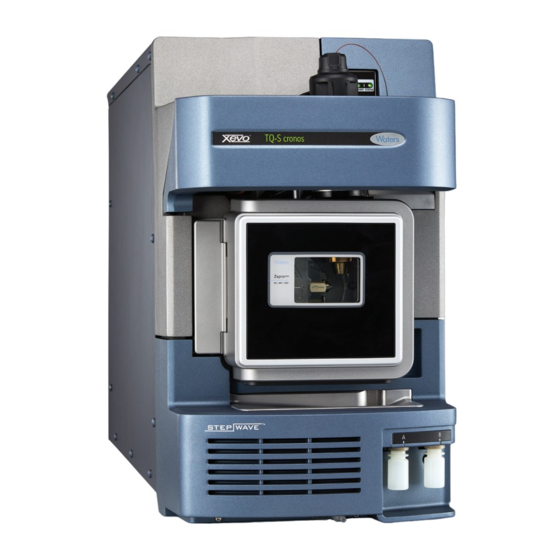
1 Waters Xevo TQ-S cronos overview The Waters Xevo TQ-S cronos is a triple quadrupole, atmospheric pressure ionization (API) mass spectrometer. Designed for routine HPLC-MS/MS and UPLC-MS/MS analyses in quantitative and qualitative applications, it can operate at fast acquisition speeds compatible with UltraPerformance LC applications. -
Page 22: Automation And Fluidics
Figure 1–1: Xevo TQ-S cronos shown with visor up and visor down Visor up 1.1 Automation and fluidics The system software (IntelliStart for MassLynx, or waters_connect) monitors instrument performance and indicates when the instrument is ready for use. The software automatically tunes and mass calibrates the instrument, displays performance readbacks, and enables simplified setup of the system for use in routine analytical applications. -
Page 23: Acquity Uplc-Ms Xevo Tq-S Cronos Systems
• Solvent tray In Waters documents, the term “fluidics” refers to the fluidics system, which is the instrument’s onboard system that delivers sample and solvent to the probe of the mass spectrometer. It can also denote plumbing components and fluid pathways within and between system modules. - Page 24 Table 1–1: ACQUITY system core components: (continued) System Core components • ACQUITY UPLC column • Software to control the system ACQUITY UPLC H-Class • Quaternary solvent manager • Sample manager with flow-through needle • Column heater–active • UPLC detectors • Solvent tray •...
- Page 25 • Arc Premier System Guide (715007449) Also see Controlling Contamination in LC/MS Systems (715001307). You can find these documents on www.waters.com by clicking Support > Support Documents and Downloads. January 10, 2022, 715006200 Ver. 01 (previously released as Rev. A)
-
Page 26: Waters Acquity Xevo Tq-S Cronos Uplc-Ms System
1.2.3 Waters ACQUITY Xevo TQ-S cronos UPLC-MS system Figure 1–2: Waters ACQUITY Xevo TQ-S cronos UPLC-MS system Sample organizer (optional) Solvent tray Column heater Xevo TQ-S cronos Sample manager Binary solvent manager 1.2.4 Software and data system You can use either of the following software to control the mass spectrometer: •... -
Page 27: Ionization Techniques And Source Probes
• Monitoring the run • Processing data • Reviewing data • Printing data 1.2.4.1 MassLynx software MassLynx software acquires, analyzes, and manages mass spectrometry, ultraviolet (UV), evaporative light scattering (ELS), and analog data. OpenLynx and TargetLynx XS application managers are included with MassLynx software. See the MassLynx software user documentation and online Help for information about using MassLynx software. -
Page 28: Esci
(solvent evaporation). As solvent continues to evaporate, the charge density increases until the droplet surfaces eject ions (ion evaporation). The ions can be singly or multiply charged. To operate the source in ESI mode, you fit the source enclosure with an ESI probe adapter and ESI probe assembly. -
Page 29: Fluidics System
1.4 Fluidics System 1.4.1 Overview The fluidics system is built into the instrument and controls how sample is delivered to the source. For standard flow applications, the system delivers sample directly to the mass spectrometer’s source in one of three ways: •... -
Page 30: System Components
Wash bottle, located in solvent tray Reservoirs A and B Syringe pump Source enclosure Probe 1.4.2 System components The onboard system incorporates a selector valve, an infusion pump, and two sample reservoirs mounted on the bottom, right-hand side of the instrument. Recommendation: Use reservoir A for the calibrant solution and tuning compounds, and reservoir B for the analyte/optimization solution. -
Page 31: Ms Operating Modes
Figure 1–4: Ion optics overview Sample cone Segmented quadrupole (ion guide 2) MS1 quadrupole T-Wave collision cell MS2 quadrupole Conversion dynode Phosphor disk Photomultiplier Stepwave (ion guide 1) Probe 1.6 MS operating modes The following table shows the MS operating modes. Table 1–2: MS operating modes: Operating mode Collision cell... -
Page 32: Ms/Ms Operating Modes
Table 1–2: MS operating modes: (continued) Operating mode Collision cell Pass all masses Resolving (static) In MS mode, the instrument can acquire data at scan speeds as high as 20,000 Da/s. Use this mode for instrument tuning and calibration before MS/MS analysis. See the mass spectrometer’s online Help for further information. -
Page 33: Product (Daughter) Ion Spectrum
1.7.1 Product (daughter) ion spectrum Product ion spectrum is the most commonly used MS/MS operating mode. You can specify an ion of interest for fragmentation in the collision cell, yielding structural information. Figure 1–5: Product ion spectrum MS1–Static (at precursor mass) Collision cell–Fragment precursor ions and pass all masses MS2–Scanning 1.7.1.1 Typical applications... -
Page 34: Mrm Mode
1.7.5 RADAR mode In RADAR mode, the Xevo TQ-S cronos rapidly alternates between MRM and full-scan MS acquisition modes. The instrument tracks target analytes with precision in MRM mode, while at January 10, 2022, 715006200 Ver. 01 (previously released as Rev. A) -
Page 35: Constant Neutral Loss Mode
the same time, scanning (in MS mode) the background for all other components. This enables fast characterization of potential matrix effects, providing a platform for more robust method development. 1.7.5.1 Typical application You typically use RADAR mode during method development prior to performing MRM or PICS to quantify known analytes in complex samples. -
Page 36: Sample Inlet
1.5 mL of accumulated leaked liquid in its surrounding reservoir. At the same time, the software displays an error message alerting you that a leak has developed. Consult the Waters ACQUITY UPLC Leak Sensor Maintenance Instructions (71500082506) for complete details. - Page 37 Figure 1–9: Mass spectrometer rear panel Video connection Event inputs and outputs Shielded Ethernet Waste bottle electrical connection Roughing pump control Source vacuum Collision cell gas inlet Nitrogen inlet Turbo vacuum Source vent Power January 10, 2022, 715006200 Ver. 01 (previously released as Rev. A) Page 37...
-
Page 38: Preparing The Mass Spectrometer For Operation
2 Preparing the mass spectrometer for operation This chapter describes how to start and shut down the mass spectrometer. 2.1 Preparing to start the mass spectrometer This instrument is compatible with the ACQUITY UPLC system. If you are not using an ACQUITY UPLC system, refer to the documentation relevant to the system you are using. -
Page 39: Starting The Mass Spectrometer Using Masslynx Software
Note: For additional information on the fluidics connections, see the diagram on the inside of the fluidics valve access door, and Plumbing schematic (Page 174). 3. Ensure that the collision gas supply is connected to the instrument’s collision cell gas inlet. Requirement: The collision gas is argon;... -
Page 40: Starting The Mass Spectrometer Using Waters_Connect Software
Tip: After a 20-second delay, during which the turbopump is starting, the roughing pump starts. IntelliStart displays “Instrument in standby”, and the Operate LED remains off. c. Wait a minimum of 2 hours for the instrument to be fully pumped-down (evacuated). Tip: In the Instrument Console, the System Ready indicator shows green when the instrument is fully pumped-down (evacuated). - Page 41 6. Navigate to the system control panel within the software. 7. From the Console Navigation pane on the left-hand side of the window, in the System pane, click the instrument (Xevo TQ-S cronos). 8. To pump the instrument, click Maintain > Maintenance > Vacuum > Pump Instrument.
-
Page 42: Verifying The Instrument's State Of Readiness
The ACQUITY UPLC system runs at high flow rates. To optimize desolvation and sensitivity, run the ACQUITY Xevo TQ-S cronos system at appropriate gas flows and desolvation temperatures. When you specify a flow rate, software automatically specifies the settings shown in the following table. -
Page 43: Preparing The Fluidics System
Table 2–1: Flow rate versus temperature and gas flow: Flow rate (mL/min) Source temperature Desolvation Desolvation gas (°C) temperature (°C) flow (L/h) 0.000 to 0.020 0.021 to 0.100 0.101 to 0.500 1,000 >0.500 1,000 2.8 Preparing the fluidics system This section contains information for preparing the fluidics system. For additional information, see Connecting liquid waste lines (Page 163) Plumbing the fluidics system (Page 173). -
Page 44: Installing The Low-Volume Vials
Figure 2–1: Installing the reservoir bottles 3. For each reservoir bottle, ensure that the ends of the solvent delivery tubes are positioned so they are close to, but not touching, the bottom of the bottle. 2.8.2 Installing the low-volume vials To install the low-volume vials: Warning: To avoid personal contamination with biologically hazardous, toxic, and corrosive... -
Page 45: Rebooting The Mass Spectrometer
2.9 Rebooting the mass spectrometer Pressing the reset button shuts down the electronics momentarily and causes the mass spectrometer to reboot. Reboot the mass spectrometer when either of these conditions applies: • The software fails to establish communication or loses communication with the mass spectrometer. -
Page 46: Emergency Shutdown Of The Mass Spectrometer
2.11 Emergency shutdown of the mass spectrometer Warning: To avoid electric shock, observe the following procedure to isolate the instrument from the main power supply. The instrument's power switch does not isolate it from the main power supply. Notice: To avoid losing data, use the following procedure only in an emergency. To reboot the mass spectrometer, follow the procedure in the section "Rebooting the mass spectrometer". -
Page 47: Changing The Mode Of Operation
• ESCi (combined electrospray and atmospheric pressure chemical ionization) • APCI (atmospheric pressure chemical ionization) • UniSpray For details about other Waters and third-party source options, refer to the documentation supplied with the source. Note: Depending on the software used to control the instrument, some sources may not be available. -
Page 48: Apci Mode
3.1.3 APCI mode APCI mode, an option for the mass spectrometer, produces singly charged protonated or deprotonated molecules for a broad range of nonvolatile analytes. The APCI interface consists of the ESI/APCI/ESCi enclosure fitted with a corona pin and an APCI probe adapter. - Page 49 Figure 3–2: Probe adapter types ESI probe adapter APCI probe adapter ESI identification label APCI probe heater ESI probe tip APCI identification label January 10, 2022, 715006200 Ver. 01 (previously released as Rev. A) Page 49...
- Page 50 Probe adapter Install corona pin ESCi APCI APCI For more information on using each mode, see the Xevo TQ-S cronos system online Help. The following sections explain how to complete the following tasks: • Installing the probe adapter (Page 51) •...
-
Page 51: Installing The Probe Adapter
3.1.5 Installing the probe adapter Figure 3–4: Probe adapter parts Probe adapter cap removed from probe adapter Probe adapter cap tether Locking ring Probe adapter identification label Probe adapter cap release buttons Required materials • Chemical-resistant, powder-free gloves To install the probe adapter: Warning: To avoid personal contamination with biologically hazardous or toxic compounds, wear clean, chemical-resistant, powder-free gloves when performing this procedure. - Page 52 1. For ESI probe adapters, remove the protective cap, if fitted, from the probe tip. Figure 3–5: ESI probe protective cap Protective cap 2. Carefully slide the probe adapter into the hole in the source enclosure's probe adjuster assembly, ensuring that the probe location dowel aligns with the location hole in the probe adjuster assembly.
- Page 53 Figure 3–8: Locating the APCI probe adapter Location hole for probe location dowel Probe adjuster assembly 3. Rotate the probe adapter locking ring clockwise to secure the probe adapter in place. Figure 3–9: Probe adapter mounted on the source enclosure Probe adapter cap Probe adapter locking ring Probe adjuster assembly...
-
Page 54: Installing The Probe Assembly
4. For ESI probe adapters, connect the ESI probe adapter’s cable to the high-voltage connector. 5. Install the probe assembly. See Installing the probe assembly (Page 54). 3.1.6 Installing the probe assembly Requirements: • Ensure that you use a probe assembly appropriate for your application. For example, using an ESI probe assembly with an APCI probe adapter compromises instrument performance. - Page 55 • The high-voltage warning label does not appear on all probe assemblies. • The fitting used for ACQUITY UPC² systems differs from the probe inlet fitting shown here. See Connecting the probe assembly to a UPC² system (Page 62). Required materials •...
- Page 56 Figure 3–12: Inserting the probe assembly Probe assembly capillary Probe adapter 3. Screw the probe adapter fitting into the probe adapter, finger-tight only, until you hear a click. Figure 3–13: Probe assembly fitted to the probe adapter Probe adapter fitting Tip: The probe adapter fitting varies in size depending on the probe assembly type.
- Page 57 the correct probe assembly. For example, the UniSpray probe assembly will not fit the tool- free probe adapter. 4. Tilt the probe adapter cap so that the ball bearing is located in the recess at the bottom of the aperture, and then insert the probe assembly tubing through the aperture. Figure 3–14: Probe adapter cap Probe cap aperture from the underside Probe cap aperture from the top...
- Page 58 Figure 3–15: Fitting the probe adapter cap Probe adapter cap Probe adapter cap tether Probe adapter Probe assembly tubing 5. Slide the probe adapter cap along the probe assembly, over the probe adapter inlet fitting. 6. Push the probe adapter cap onto the probe adapter until it clicks. Tips: •...
- Page 59 Figure 3–16: Seating the probe adapter cap Probe adapter cap seated incorrectly: edge does not align with the edge of the probe adapter Probe adapter cap seated correctly: edge aligns with the edge of the probe adapter Note: If you fit the probe adapter cap when the source enclosure is closed and the mass spectrometer is in Operate, the high-voltage supply to the probe turns on and the instrument performs a pressure test.
-
Page 60: Removing And Refitting The Probe Inlet Fitting
Probe assembly tubing Warning: To avoid electric shock or solvent ignition, when connecting ESI or source probes directly to non-Waters equipment, ensure that the liquid outlet connection is grounded. 7. Connect the probe inlet fitting to the inlet system. Note:... - Page 61 Required materials • Chemical-resistant, powder-free gloves To remove the probe inlet fitting: Warning: To avoid personal contamination with biologically hazardous or toxic compounds, wear clean, chemical-resistant, powder-free gloves when performing this procedure. 1. Pull the inlet fitting from the end of the probe assembly. Tip: Hold the fitting spring retainer in place while the probe inlet fitting is removed to prevent it from sliding along the probe assembly.
-
Page 62: Connecting The Probe Assembly To A Upc² System
Figure 3–19: Fitting the probe inlet fitting Fitting spring retainer Probe inlet fitting 3.1.8 Connecting the probe assembly to a UPC² system To connect the probe assembly to a UPC² system, first fit the supplied UPC² inlet fitting to the end of the probe assembly. - Page 63 Figure 3–20: Fitting the compression nut, backing ring, and ferrule to the probe assembly Compression nut Backing ring Ferrule 2. Insert the probe assembly into the ISM's restrictor port until you encounter resistance. Figure 3–21: Connecting the probe assembly to the ISM Compression nut, backing ring, and ferrule To ISM restrictor port 3.
-
Page 64: Removing The Probe Adapter
5. If you are connecting the probe assembly for the first time, using a 1/4-inch open-end wrench, tighten the compression nut until you feel an increase in resistance, and then tighten by another 3/4-turn. Figure 3–22: 3/4-turn If you are refitting a previously installed probe assembly, using a 1/4-inch open-end wrench, tighten the compression nut up to a 1/6-turn. -
Page 65: Installing And Removing The Corona Pin
Warning: To avoid burn injuries, take great care while working with the probe and source; these components can be hot. 1. For ESI probes, disconnect the probe adapter cable from the high voltage connector. 2. Unscrew the probe adapter locking ring. Warning: To avoid puncture wounds, handle sharp parts and materials with care. - Page 66 Figure 3–24: Corona pin mounting contact Corona pin mounting contact blanking plug Warning: To avoid puncture wounds, handle sharp parts and materials with care. 4. Fit the corona pin to the corona pin mounting contact, ensuring that the corona pin is securely mounted and that its tip aligns with the sample cone orifice.
-
Page 67: Unispray Standard Source
3.1.10.2 Removing the corona pin from the source Required materials Chemical-resistant, powder-free gloves To remove the corona pin from the source: Warning: To avoid personal contamination with biologically hazardous, toxic, and corrosive materials, wear chemical-resistant, powder-free gloves when performing this procedure. Warning: To avoid static-like electric shock, ensure that the instrument is prepared for working on the source before starting this procedure. - Page 68 Figure 3–26: UniSpray standard source – front Probe PEEK fitting Probe assembly Vertical probe adjuster Horizontal probe adjuster Source enclosure door release-handle January 10, 2022, 715006200 Ver. 01 (previously released as Rev. A) Page 68...
-
Page 69: Installing The Unispray Source
Figure 3–27: UniSpray standard source – rear Capillary adjuster Impactor pin Cable storage sockets Probe adjuster overflow spur and probe storage clip See also: Topics about maintaining the source components: • Replacing the UniSpray probe assembly (Page 135) • Maintaining the impactor pin (Page 138) 3.2.1 Installing the UniSpray source 3.2.1.1 Installing the UniSpray standard source Required materials... - Page 70 Warning: To avoid personal contamination with biologically hazardous, toxic, and corrosive materials, wear chemical-resistant, powder-free gloves when performing this procedure. Important: Before installing the UniSpray standard source, inspect the UniSpray source's impactor pin to determine whether it requires cleaning or replacement according to the maintenance schedule.
- Page 71 Source enclosure door release handle 5. Slide open the instrument's source control panel door. 6. Connect the impactor pin high-voltage cable to the impactor pin high-voltage cable socket on the mass spectrometer. Figure 3–29: UniSpray standard source connections Probe assembly Impactor pin high-voltage cable Probe adjuster cable (yellow) 7.
-
Page 72: Removing The Unispray Source
3.2.2 Removing the UniSpray source 3.2.2.1 Removing the UniSpray standard source You can remove the UniSpray source and replace it with another compatible interface. Required materials • Chemical-resistant, powder-free gloves Warning: To avoid personal contamination with biologically hazardous, toxic, and corrosive materials, wear chemical-resistant, powder-free gloves when performing this procedure. - Page 73 Storage clip on the overflow spur 3. Swing open the UniSpray source enclosure unit from the source mounting on the mass spectrometer. 4. Disconnect the probe adjuster cable (yellow) from the instrument source interface panel. 5. Disconnect the impactor pin high-voltage cable from the instrument source interface panel. 6.
-
Page 74: Maintenance Procedures
Keep to a maintenance schedule, and perform maintenance as required and described in this section. 4.1 Maintenance schedule for Xevo TQ-S cronos The following table lists periodic maintenance schedules that ensure optimum instrument performance. Table 4–1: Maintenance schedule... -
Page 75: Spare Parts
(Page 133). 4.2 Spare parts To ensure that your system operates as designed, use only Waters Quality Parts. Visit www.waters.com/wqp for information about Waters Quality Parts, including how to order them. January 10, 2022, 715006200 Ver. 01 (previously released as Rev. A) -
Page 76: Safety And Handling
4.3 Safety and handling Bear in mind the following safety considerations when performing maintenance procedures: Warning: To avoid personal contamination with biologically hazardous, toxic, and corrosive materials, wear chemical-resistant, powder-free gloves when performing this procedure. Warning: Observe Good Laboratory Practice (GLP) at all times, particularly when working with hazardous materials. -
Page 77: Using Masslynx Software To Prepare The Instrument For Operations On Or Inside Its Source
LC flow. Note: If column flow is required, divert the LC flow to waste: a. In the Instrument Console system tree, expand Xevo TQ-S cronos Detector, Interactive Fluidics. b. Click Control c. Select Waste as the flow state. -
Page 78: Removing And Refitting The Source Enclosure
4. Wait three minutes to allow the desolvation gas flow to cool the probe and source. 5. Lift the visor on the front of the instrument so that it is clear of all the source components and probe. 4.5 Removing and refitting the source enclosure Before performing certain maintenance procedures, or fitting the optional sources to the instrument, you must remove the source enclosure that is currently fitted to the instrument. -
Page 79: Fitting The Source Enclosure To The Instrument
Figure 4–1: Removing the source enclosure Supporting stud Source enclosure Cable storage positions 6. Store the cables neatly by plugging them into the cable-storage positions on the rear of the source enclosure. 4.5.2 Fitting the source enclosure to the instrument Required materials Chemical-resistant, powder-free gloves To fit the source enclosure to the instrument:... -
Page 80: Operating The Source Isolation Valve
1. Using both hands, fit the source enclosure to the two supporting studs on the source adapter housing. Notice: To avoid damaging the sample inlet, when removing a NanoLockSpray source enclosure, you must slide the sprayer platform out of the source enclosure before you open the enclosure. -
Page 81: Opening The Source Isolation Valve
3. Close the source isolation valve by turning its handle counterclockwise to the vertical position. Figure 4–2: Closing the source isolation valve Isolation valve handle in closed position 4.6.2 Opening the source isolation valve To open the source isolation valve after completing a maintenance procedure: Warning: To avoid personal contamination with biologically hazardous, toxic, and corrosive materials, wear chemical-resistant, powder-free gloves when performing this procedure. -
Page 82: Removing O-Rings And Seals
Figure 4–3: Source isolation valve opened Isolation valve handle in open position 2. Close the source enclosure. 4.7 Removing O-rings and seals You must remove O-rings or seals from instrument components when performing certain maintenance procedures. 4.7.1 O-ring removal kit Note: The O-ring removal kit (700005054) is available to order separately. -
Page 83: Cleaning The Instrument Case
To remove an O-ring: Notice: To avoid damaging the component when removing an O-ring or seal from it, ensure that you do not scratch the component with the removal tool. Use the tools as aids to pull the O-ring or seal from its groove. Tip: If you do not plan to reuse the O-ring or seal, you can use the forked end of tool 1 to impale the O-ring or seal to remove it. - Page 84 Figure 4–5: Nitrogen exhaust trap bottle To laboratory exhaust port Valve control cable (from instrument) Bottle support Nitrogen exhaust trap bottle From instrument exhaust connection One-way valve January 10, 2022, 715006200 Ver. 01 (previously released as Rev. A) Page 84...
-
Page 85: Maintaining The Rotary Backing Pump's Oil
Required materials Chemical-resistant, powder-free gloves To empty the nitrogen exhaust trap bottle: 1. In the instrument console, click Stop Flow 2. Pull the source enclosure release (located at the bottom, right-hand side) outward and swing open the enclosure. Warning: To avoid personal contamination with biologically hazardous, toxic, and corrosive materials, wear chemical-resistant, powder-free gloves when performing this procedure. - Page 86 Required tools and materials • Chemical-resistant, powder-free gloves • Tray on which to place the pump • Container to catch used oil • Suitable pump oil Warning: To avoid personal contamination with biologically hazardous or toxic compounds, wear clean, chemical-resistant, powder-free gloves when performing this procedure. Warning: To avoid burn injuries, allow the pump to cool before touching surfaces displaying the burn warning symbol.
- Page 87 Figure 4–6: Backing pump rear panel Oil level sight glass Oil drain plug 6. Tilt the pump slightly and catch the oil in a suitable container. 7. Dispose of the oil according to local environmental regulations. 8. Insert the oil drain plug into the pump’s rear panel. 9.
-
Page 88: Cleaning The Source Components
Notice: Do not fill the pump beyond the “max” mark. 15. Refit the oil inlet plug. 4.11 Cleaning the source components Clean the sample cone and cone gas nozzle when the following conditions apply: • The sample cone and cone gas nozzle are visibly fouled. •... - Page 89 Warning: To avoid puncture wounds, take great care while working with the source enclosure open if one or both of these conditions apply: • An ESI probe is fitted (the probe’s tip is sharp). • A corona pin is fitted (the pin’s tip is sharp). Warning: To avoid burn injuries, take great care while working with the source enclosure open.
-
Page 90: Disassembling The Sampling Cone Assembly
Notice: To avoid damage, do not open the source isolation valve before fitting the sampling cone assembly to the ion block assembly. 4.12.2 Disassembling the sampling cone assembly Required materials • Chemical-resistant, powder-free gloves • Combined 2.5-mm hex wrench and cone extraction tool To disassemble the sampling cone assembly: Warning: To avoid personal contamination with biologically hazardous, toxic, and corrosive... - Page 91 Figure 4–10: Cone extraction tool Collar 3. Insert the collar in the sample cone. Figure 4–11: Inserting the cone extraction tool Insert the collar Notice: To avoid damaging the sampling cone, which is fragile, do not place it on its tip. Always place it on its flanged base. 4.
-
Page 92: Cleaning The Sample Cone And Cone Gas Nozzle
Remove the sample cone 5. Remove the O-ring from the sample cone. Figure 4–13: O-ring removed from the sample cone Cone gas nozzle Sample cone O-ring Cone gas nozzle handle Warning: To avoid spreading contamination with biologically hazardous, toxic, and corrosive materials, dispose of all waste materials according to local environmental regulations. - Page 93 • Oil-free argon gas or Oil-free nitrogen gas • Wash bottle containing HPLC-grade (or better) 1:1 methanol/water • Large beaker To clean the sample cone and cone gas nozzle: Warning: To avoid personal contamination with biologically hazardous, toxic, and corrosive materials, wear chemical-resistant, powder-free gloves when performing this procedure.
-
Page 94: Assembling The Sampling Cone Assembly
a. Use the wash bottle containing 1:1 methanol/water to rinse the component over the large beaker. b. Blow dry the component with inert, oil-free gas. Warning: To avoid spreading contamination with biologically hazardous, toxic, and corrosive materials, dispose of all waste materials according to local environmental regulations. -
Page 95: Fitting The Sampling Cone Assembly To The Source
Cone gas nozzle Cone gas nozzle handle Note: The PEEK handle is removable on earlier models of the cone gas nozzle assembly. If you detached the handle from the cone gas nozzle for cleaning, replace the handle and tighten it. 2. -
Page 96: Cleaning The Ion Block Assembly
Figure 4–15: Fitting the sampling cone assembly Ion block assembly Sampling cone assembly 3. Grasp the cone gas nozzle handle, and use it to rotate the sampling cone assembly 90 degrees, moving the handle downward from the horizontal to the vertical position. 4. - Page 97 Warning: To avoid personal contamination with biologically hazardous, toxic, and corrosive materials, wear chemical-resistant, powder-free gloves when performing this procedure. 1. Vent and shut down the mass spectrometer (see the mass spectrometer’s online Help for details). Warning: To avoid personal injury, as well as damage to the roughing pump and mass spectrometer, disconnect the power cords for the mass spectrometer and roughing pump from the main power source.
-
Page 98: Disassembling The Source Ion Block Assembly
Figure 4–17: Removing the ion block assembly PEEK ion block support Ion block assembly 4.13.2 Disassembling the source ion block assembly Required materials • Chemical-resistant, powder-free gloves • Combined 2.5-mm hex wrench and cone extraction tool • O-ring removal kit To disassemble the ion block assembly: Warning: To avoid personal contamination with biologically hazardous, toxic, and corrosive... - Page 99 Figure 4–18: Source ion block assembly Source isolation valve handle in closed position Sampling cone assembly retaining blocks Cone gas nozzle handle 2. Grasp the cone gas nozzle handle and use it to rotate the sampling cone assembly through 90 degrees. 3.
- Page 100 Figure 4–19: Source ion block cover plate Ion block cover plate securing screw Ion block cover plate 5. Remove the ion block cover plate. 6. Grasp the isolation valve and pull it out of the ion block. Figure 4–20: Removing the isolation valve from the ion block Isolation valve O-ring 7.
- Page 101 Warning: To avoid spreading contamination with biologically hazardous, toxic, and corrosive materials, dispose of all waste materials according to local environmental regulations. 8. If the isolation valve O-ring shows signs of deterioration or damage, dispose of it in accordance with local environmental regulations. 9.
- Page 102 Figure 4–22: Removing the PEEK terminal block and ceramic heater mounting block Ceramic heater mounting block PEEK terminal block 11. Use the O-ring removal kit to carefully remove the cover seal from the ion block (see also Removing O-rings and seals (Page 82)).
-
Page 103: Cleaning The Ion Block Components
Warning: To avoid spreading contamination with biologically hazardous, toxic, and corrosive materials, dispose of all waste materials according to local environmental regulations. 13. If the cover seal or cone gas O-ring shows signs of deterioration or damage, dispose of it in accordance with local environmental regulations. -
Page 104: Assembling The Source Ion Block Assembly
a. Rinse the components by immersing them separately in glass vessels containing water, and then placing the vessels in the ultrasonic bath for 20 minutes. b. Remove residual water from the components by immersing them in separate glass vessels containing methanol, and then placing the vessels in the ultrasonic bath for 10 minutes. -
Page 105: Fitting The Ion Block Assembly To The Source Assembly
1. Carefully fit the PEEK terminal block and ceramic heater mounting block, complete with heater cartridge assembly, to the ion block. 2. Use the combined 2.5-mm hex wrench and cone extraction tool to tighten the captive PEEK terminal block securing screw. 3. -
Page 106: Cleaning The Ion Guide Assembly
Warning: To avoid puncture wounds, take great care while working with the source enclosure open if one or both of these conditions apply: • An ESI probe is fitted (the probe’s tip is sharp). • A corona pin is fitted (the pin’s tip is sharp). Notice: To avoid recontaminating the components, wear clean, chemical-resistant, powder-free gloves. - Page 107 To remove the pumping block assembly and ion guide assembly from the instrument: 1. Remove the source enclosure from the instrument (see Removing and refitting the source enclosure (Page 78)). 2. Use the 3-mm hex wrench to unscrew and remove the 4 screws securing the pump block assembly to the instrument.
-
Page 108: Removing The Ion Guide Assembly And Differential Aperture From The Pumping Block Assembly
4.14.2 Removing the ion guide assembly and differential aperture from the pumping block assembly Required materials • Chemical-resistant, powder-free gloves • 3-mm hex wrench Warning: To avoid personal contamination with biologically hazardous, toxic, and corrosive materials, wear chemical-resistant, powder-free gloves when performing this procedure. To remove the ion guide assembly and differential aperture from the pumping block assembly: 1. -
Page 109: Removing The Differential Aperture Support And The Differential Aperture From The Ion Guide Assembly
2. Grasping the ion guide assembly by its top and bottom circuit boards, carefully remove the differential aperture and ion guide assembly from the pumping block assembly. 4.14.3 Removing the differential aperture support and the differential aperture from the ion guide assembly Required materials •... -
Page 110: Cleaning The Differential Aperture
Use only glassware not previously cleaned with surfactants. • Ultrasonic bath • HPLC-grade deionized water • Waters MS Cleaning Solution (186006846) or HPLC-grade (or better) 1:1 methanol/water • HPLC-grade isopropyl alcohol • Suitable holding container for storing the used cleaning solution •... -
Page 111: Cleaning The Ion Guide Assembly
To clean the differential aperture: 1. Place the differential aperture in the glass vessel for cleaning. 2. Add Waters MS Cleaning Solution or 1:1 methanol/water to the vessel until the differential aperture is immersed completely. 3. Place the cleaning vessel with the differential aperture in an ultrasonic bath for 20 minutes. - Page 112 Opposite end hook used to suspend the ion guide assembly Rear circuit board carrier on the ion guide assembly 4. Add Waters MS Cleaning Solution or 1:1 methanol/water to the cleaning glass vessel until the ion guide assembly is immersed completely.
-
Page 113: Fitting The Differential Aperture And The Differential Aperture Support Onto The Ion Guide Assembly
9. Pour the used cleaning solution from the cleaning vessel into the holding container. Tip: You can reuse Waters MS Cleaning Solution for one subsequent cleaning. 4.14.6 Fitting the differential aperture and the differential aperture support onto the ion guide assembly Required materials •... -
Page 114: Fitting The Ion Guide Assembly And Differential Aperture Onto The Pumping Block Assembly
Warning: To avoid spreading contamination with biologically hazardous, toxic, and corrosive materials, dispose of all waste materials according to local environmental regulations. 2. Use the flat-blade screwdriver to fit and tighten the 3 screws that secure the differential aperture to the differential aperture support. 3. -
Page 115: Fitting The Pumping Block Assembly And Ion Guide Assembly Onto The Instrument
Figure 4–28: Fitting the ion guide assembly and differential aperture Pumping block assembly Ion guide assembly Differential aperture support and circuit board Securing screws (2) 2. Use the 3-mm hex wrench to thread and tighten the 2 screws used to fit the differential aperture and ion guide assembly boards to the pumping block assembly. -
Page 116: Replacing The Ion Block Source Heater
To fit the pumping block assembly and ion guide assembly onto the instrument: 1. Using care not to damage the seals between the pumping block assembly and instrument, position the pumping block assembly and ion guide assembly onto the instrument. Figure 4–29: Fitting the pumping block and ion guide assemblies Ion guide assembly Housing... - Page 117 Required materials • Chemical-resistant, powder-free gloves • Needle-nose pliers • Combined 2.5-mm hex wrench and cone extraction tool • New ion block source heater assembly To replace the ion block source heater: Warning: To avoid personal contamination with biologically hazardous, toxic, and corrosive materials, wear chemical-resistant, powder-free gloves when performing this procedure.
- Page 118 Figure 4–31: Loosening the captive screws Ion block cover plate securing screw Ion block cover plate 4. Remove the ion block cover plate. 5. Use the combined 2.5-mm hex wrench and cone extraction tool to loosen the captive PEEK terminal block securing screw. Figure 4–32: Loosening the captive PEEK terminal block securing screw Heater cartridge assembly wires PEEK terminal block securing screw...
- Page 119 Tip: You can invert the ion block assembly to facilitate this process. Figure 4–33: Removing the PEEK terminal block Heater wire securing screws PEEK terminal block Ceramic heater mounting block 7. Use the combined 2.5-mm hex wrench and cone extraction tool to loosen the two screws securing the heater wires to the PEEK terminal block.
-
Page 120: Replacing The Probe Assembly
Notice: To avoid damaging the heater cartridge assembly wires, do not bend or twist them when removing the assembly and ceramic heater mounting block from the ion block. 11. Use the needle-nose pliers to gently grasp the heat-shrink tubing on the new heater cartridge assembly and slide the assembly into the ceramic heater mounting block. - Page 121 Warning: To avoid electric shock or solvent ignition, when connecting ESI or UPC source probes directly to non-Waters equipment, ensure that the liquid outlet connection is grounded. 1. Squeeze the probe adapter cap release buttons together and lift the probe cap off the probe adapter, sliding it over the probe assembly.
-
Page 122: Replacing The Esi Probe Tip And Gasket
Figure 4–36: PEEK fitting PEEK fitting 3. Remove the probe assembly. Warning: To avoid spreading contamination with biologically hazardous, toxic, and corrosive materials, dispose of all waste materials according to local environmental regulations. 4. Dispose of the probe assembly in accordance with local environmental regulations. 5. - Page 123 To remove the ESI probe tip and gasket: Warning: To avoid personal contamination with biologically hazardous materials, wear clean, chemical-resistant, powder-free gloves when performing this procedure. Warning: To avoid burn injuries, take great care while performing this procedure. Warning: To avoid puncture injuries, handle sample needles, syringes, fused silica lines, and borosilicate tips with extreme care.
-
Page 124: Fitting The Esi Probe Tip And Gasket
Figure 4–38: Removing the metal gasket Metal gasket Warning: To avoid spreading contamination with biologically hazardous, toxic, and corrosive materials, dispose of all waste materials according to local environmental regulations. 4. Dispose of the metal gasket in accordance with local environmental regulations. 5. -
Page 125: Cleaning The Apci Probe Tip
Figure 4–39: Inserting the gasket Metal gasket ESI probe tip Stainless steel tube 2. Fit the probe tip, and screw the tip onto the probe assembly. 3. Use the 7-mm wrench in conjunction with the 10-mm wrench to tighten the probe tip. Important: To avoid gas leakage, fully tighten the probe tip. -
Page 126: Replacing The Apci Probe Heater
4.19 Replacing the APCI probe heater Replace the APCI probe heater if it fails to heat the probe. 4.19.1 Removing the APCI probe heater Required materials Chemical-resistant, powder-free gloves To remove the APCI probe heater: Warning: To avoid burn injuries, take great care while working with the probe and source;... -
Page 127: Fitting The New Apci Probe Heater
Warning: To avoid burn injuries, take great care while performing this procedure. 2. Gripping the probe heater as shown, carefully pull it off the probe adapter. Figure 4–41: Removing the probe heater Probe heater Warning: To avoid spreading contamination with biologically hazardous, toxic, and corrosive materials, dispose of all waste materials according to local environmental regulations. - Page 128 Figure 4–42: Fitting the probe heater Capillary sleeve Probe heater connections Notice: To avoid damaging the probe heater's electrical connections, do not twist the heater when removing it from or refitting it to the probe adapter. 2. Fit the probe adapter to the instrument (see Installing the probe adapter (Page 51)).
-
Page 129: Cleaning Or Replacing The Corona Pin
4.20 Cleaning or replacing the corona pin Required materials • Chemical-resistant, powder-free gloves • Needle-nose pliers • HPLC-grade methanol • Lint-free tissue • Lapping film • Corona pin To clean or replace the corona pin: Warning: To avoid personal contamination with biologically hazardous, toxic, and corrosive materials, wear chemical-resistant, powder-free gloves when performing this procedure. -
Page 130: Replacing The Source Assembly Seals
4.21 Replacing the source assembly seals Warning: To avoid spreading contamination, dispose of the O-ring or seal according to local environmental regulations. O-rings and seals can be contaminated with biohazardous or toxic materials. Warning: To avoid excessive leakage of biologically hazardous or toxic solvent vapor into the laboratory atmosphere, the seals listed below must be renewed, at intervals of no greater than one year, exactly as described in this section. - Page 131 • Probe seal • Nebulizer gas seal See also: Removing O-rings and seals. (Page 82) Figure 4–43: Probe adjuster assembly seals Probe adjuster nebulizer gas seal Probe adjuster assembly probe seal 3. Use the O-ring removal kit to carefully remove the following seals from the source enclosure: •...
-
Page 132: Fitting The New Source Enclosure And Probe Adjuster Assembly Probe Seals
Source enclosure seal Warning: To avoid spreading contamination with biologically hazardous, toxic, and corrosive materials, dispose of all waste materials according to local environmental regulations. 4. Dispose of all the seals in accordance with local environmental regulations. 4.21.2 Fitting the new source enclosure and probe adjuster assembly probe seals Required materials •... -
Page 133: Replacing The Air Filter
Figure 4–45: Fitting the seal into the groove Seal Groove 4. Fit the following new seals to the probe adjuster assembly: • Probe seal • Nebulizer gas seal 5. Fit the source enclosure to the instrument (see Fitting the source enclosure to the instrument (Page 79)). - Page 134 Figure 4–46: Source enclosure open Air filter grill Probe cable 4. Open the air filter grill by pulling the tab at the top of the grill toward you. Figure 4–47: Replacing the air filter Air filter tab Air filter grill January 10, 2022, 715006200 Ver.
-
Page 135: Replacing The Unispray Probe Assembly
Warning: To avoid spreading contamination with biologically hazardous, toxic, and corrosive materials, dispose of all waste materials according to local environmental regulations. 5. Remove and dispose of the old filter. 6. Place the new filter flat on the inside part of the grill, with its edges beneath the metal lip. 7. -
Page 136: Installing The Unispray Probe Assembly
Figure 4–48: UniSpray probe assembly PEEK fitting Probe fitting Probe capillary 3. Unscrew the probe fitting and pull the probe assembly out of the shaft inlet on top of the source enclosure. Warning: To avoid lacerations, puncture injuries, and possible contamination with biologically hazardous and toxic materials, do not touch the sharp end of the capillary. - Page 137 Notice: Ensure that you install the correct probe capillary assembly for your probe type. Using the incorrect probe capillary assembly for the probe type can compromise instrument performance. To install the UniSpray probe assembly: 1. To prepare the instrument for working on the source, stop solvent flow, ensure that the instrument is in Standby mode, and stop desolvation gas flow.
-
Page 138: Maintaining The Unispray Impactor Pin
5. Screw the probe assembly's PEEK fitting into the appropriate fluidics port for your instrument until it is finger tight. 4.24 Maintaining the UniSpray impactor pin UniSpray directs the spray at an impactor pin held at a voltage, creating smaller charged droplets, amenable to easy desolvation. -
Page 139: Cleaning Or Replacing The Unispray Impactor Pin
2. Pull open the source enclosure release handle and swing open the enclosure. 3. Unscrew the pin handle and withdraw the pin from the mounting block. 4. Dispose of the used pin in accordance with local environmental regulations. Important: When you install a new impactor pin, or you clean the existing pin based on the maintenance schedule, clean the pin before you insert it into the source, as specified in Cleaning or replacing the UniSpray impactor pin (Page 139). -
Page 140: Replacing The Instrument's Fuses
4. Install the impactor pin in the UniSpray source (see Removing and installing the UniSpray impactor pin (Page 138)). 4.25 Replacing the instrument’s fuses Warning: To avoid electric shock, disconnect the mass spectrometer from the power supply before replacing fuses. The mass spectrometer has two fuses and uses double pole/neutral fusing circuitry. -
Page 141: A Safety Advisories
Heed all warnings when you install, repair, or operate any Waters instrument or device. Waters accepts no liability in cases of injury or property damage resulting from the failure of individuals to comply with any safety precaution when installing, repairing, or operating any of its instruments or devices. -
Page 142: Specific Warnings
(Risk of high-pressure gas release.) A.1.1 Specific warnings A.1.1.1 Burst warning This warning applies to Waters instruments and devices fitted with nonmetallic tubing. Warning: To avoid injury from bursting, nonmetallic tubing, heed these precautions when working in the vicinity of such tubing when it is pressurized: •... - Page 143 A.1.1.4 Biohazard warning The following warning applies to Waters instruments and devices that can process biologically hazardous materials. Biologically hazardous materials are substances that contain biological agents capable of producing harmful effects in humans.
-
Page 144: Notices
Warning: To avoid personal contamination with biologically hazardous, toxic, or corrosive materials, you must understand the hazards associated with their handling. Guidelines prescribing the proper use and handling of such materials appear in the latest edition of the National Research Council's publication, Prudent Practices in the Laboratory: Handling and Management of Chemical Hazards. -
Page 145: Warnings That Apply To All Waters Instruments And Devices
A.5 Warnings that apply to all Waters instruments and devices When operating this device, follow standard quality-control procedures and the equipment guidelines in this section. Warning: Changes or modifications to this unit not expressly approved by the party responsible for compliance could void the user’s authority to operate the equipment. - Page 146 Warning: Use caution when working with any polymer tubing under pressure: • Always wear eye protection when near pressurized polymer tubing. • Extinguish all nearby flames. • Do not use tubing that has been severely stressed or kinked. • Do not use nonmetallic tubing with tetrahydrofuran (THF) or concentrated nitric or sulfuric acids.
- Page 147 Avvertenza: fare attenzione quando si utilizzano tubi in materiale polimerico sotto pressione: • Indossare sempre occhiali da lavoro protettivi nei pressi di tubi di polimero pressurizzati. • Spegnere tutte le fiamme vive nell'ambiente circostante. • Non utilizzare tubi eccessivamente logorati o piegati. •...
- Page 148 • 非金属チューブには、テトラヒドロフラン(THF)や高濃度の硝酸または硫酸などを 流さないでください。 • 塩化メチレンやジメチルスルホキシドは、非金属チューブの膨張を引き起こす場合 があり、その場合、チューブは極めて低い圧力で破裂します。 This warning applies to Waters instruments fitted with nonmetallic tubing or operated with flammable solvents. Warning: The user shall be made aware that if the equipment is used in a manner not specified by the manufacturer, the protection provided by the equipment may be impaired.
-
Page 149: Warnings That Address The Replacement Of Fuses
警告: 使用者必須非常清楚如果設備不是按照製造廠商指定的方式使用,那麼該設備 所提供的保護將被消弱。 경고 제조업체가 명시하지 않은 방식으로 장비를 사용할 경우 장비가 제공하는 보호 수 단이 제대로 작동하지 않을 수 있다는 점을 사용자에게 반드시 인식시켜야 합니다. 警告 ユーザーは、製造元により指定されていない方法で機器を使用すると、機器が 提供している保証が無効になる可能性があることに注意して下さい。 A.6 Warnings that address the replacement of fuses The following warnings pertain to instruments and devices equipped with user-replaceable fuses. Information describing fuse types and ratings sometimes, but not always, appears on the instrument or device. -
Page 150: Electrical Symbols
警告 火災予防のために、ヒューズ交換では機器ヒューズカバー脇のパネルに記載さ れているタイプおよび定格のヒューズをご使用ください。 Finding fuse types and ratings when that information does not appear on the instrument or device: Warning: To protect against fire, replace fuses with those of the type and rating indicated in the “Replacing fuses” section of the Maintenance Procedures chapter. Avertissement : pour éviter tout risque d'incendie, remplacez toujours les fusibles par d'autres du type et de la puissance indiqués dans la rubrique "Remplacement des... -
Page 151: Handling Symbols
Symbol Description Electrical power off Standby Direct current Alternating current Alternating current (three phase) Safety ground Frame or chassis terminal connection Fuse Functional ground Input Output Indicates that the device or assembly is susceptible to damage from electrostatic discharge (ESD) A.8 Handling symbols The following handling symbols and their associated statements can appear on labels affixed to the packaging in which instruments, devices, and component parts are shipped. - Page 152 Symbol Description Fragile! Use no hooks! Upper limit of temperature Lower limit of temperature Temperature limitation January 10, 2022, 715006200 Ver. 01 (previously released as Rev. A) Page 152...
-
Page 153: B External Connections
To avoid damaging the mass spectrometer, observe the following precautions: • Contact Waters Technical Service before moving the instrument. • If you must transport the instrument, or remove it from service, contact Waters Technical Service for recommended cleaning, flushing, and packaging procedures. - Page 154 Shielded Ethernet Waste bottle electrical connection Roughing pump control Source vacuum Collision cell gas inlet (argon) Nitrogen inlet Turbo vacuum Source vent Power January 10, 2022, 715006200 Ver. 01 (previously released as Rev. A) Page 154...
-
Page 155: Connecting The Edwards Oil-Filled Backing Pump
B.2 Connecting the Edwards oil-filled backing pump Figure B–2: Connecting the backing pump Exhaust port Vacuum hose assembly Power cable connector Required tools and materials • Chemical-resistant, powder-free gloves • 7-mm nut driver • 8-mm hex wrench • Utility knife •... - Page 156 • NW25 O-ring (included in the installation kit) • PVC exhaust tubing (included in the installation kit) • PVC hose clamps (included in the installation kit) • 25-mm ID vacuum hose (included in the installation kit) Warning: To avoid personal contamination with biologically hazardous or toxic compounds, wear clean, chemical-resistant, powder-free gloves when performing this procedure.
- Page 157 To connect the backing pump: Warning: To avoid skeletal or muscle injury associated with lifting heavy objects, enlist the appropriate number of people to lift an instrument or device. If necessary, use lifting equipment that can raise it to the height of the laboratory bench. 1.
-
Page 158: Making The Electrical Connections To The Rotary Backing Pump
B.2.1 Making the electrical connections to the rotary backing pump Figure B–4: Backing pump electrical connections Backing pump control cable To power source To make the electrical connections to the rotary backing pump: 1. Connect the pump control cable from the pump to the backing pump connector on the instrument’s rear panel. - Page 159 • 6-mm PTFE tubing (included in the Waters Xevo TQ-S cronos Installation Kit) • Nitrogen regulator To connect the nitrogen gas supply: 1. Attach the nitrogen regulator to the nitrogen supply. 2. Install the 6-mm stud into the regulator outlet.
-
Page 160: Connecting To The Collision Cell Gas Supply
Required materials • Chemical-resistant, powder-free gloves • Utility knife • 12-mm PTFE tubing (included in the Waters Rough Pump Connect Kit) • Snoop (or equivalent) leak detector liquid To connect the nitrogen exhaust line: January 10, 2022, 715006200 Ver. 01 (previously released as Rev. A) - Page 161 Warning: To prevent the nitrogen exhaust from carrying biologically hazardous, toxic, or corrosive LC solvents, you must use a nitrogen exhaust trap bottle and a laboratory exhaust system. The laboratory exhaust system must provide a minimum vacuum of 0.20 kPa (2 mbar, 0.03 psi) below atmospheric pressure (negative pressure).
- Page 162 Figure B–7: Connecting the nitrogen exhaust line To laboratory exhaust port (12 mm) Valve control cable (from instrument) Bottle support Nitrogen exhaust trap bottle From instrument waste (12 mm) One-way valve January 10, 2022, 715006200 Ver. 01 (previously released as Rev. A) Page 162...
-
Page 163: Connecting Liquid Waste Lines
B.6 Connecting liquid waste lines To ensure that waste materials are safely drained to the waste container, connect both the bottle tray and the mass spectrometer’s drain cup to the waste container. Required materials • Chemical-resistant, powder-free gloves • Waste container To connect the liquid waste line: Warning: To avoid personal contamination with biologically hazardous, toxic, and corrosive... -
Page 164: Connecting To The Workstation
• Do not crimp or bend drain lines. A crimp or bend can impede flow to the waste container. • Empty the waste container before the lower ends of the drain tubes are covered by waste solvent. 3. Route the waste lines to the waste container. If necessary, shorten the waste tubes so their ends are above the surface of the waste solvent. -
Page 165: Connecting The Workstation To The Power Source
Requirement: Use shielded network cables with the instrument to reduce susceptibility to radio and electrical frequency interference. To connect the workstation: 1. Connect the monitor to the workstation PC. 2. Connect one end of the shielded, crossover, network cable to the port labeled instrument LAN on the workstation rear panel. -
Page 166: I/O Signal Connectors
B.9 I/O signal connectors Warning: To avoid electric shock, all electrical connections to the rear panel must be separated from hazardous voltages by double or reinforced insulation. Circuits of this type are classified as safety extra low voltage (SELV). Examples of circuits that are typically SELV include contact closure inputs and outputs for auto-samplers, and UV, RI, and fluorescence detector signal outputs for LC-MS systems. -
Page 167: Making I/O Signal Connections
Figure B–11: I/O signal connector II Inject start (In) Inject start (In) Ground Event (In) Event (In) Switch 3 (Out) Switch 3 (Out) Ground Switch 4 (Out) Switch 4 (Out) B.9.1 Making I/O signal connections Table B–1: Instrument analog-out/event-in connections Signal connections Description Analog (Out) - Page 168 Table B–1: Instrument analog-out/event-in connections (continued) Signal connections Description Event (In) Allows an external device to start data acquisition. Maximum 30 V. Switch 2 (Out) Used to send time-based contact closure signals to external devices. Maximum 30 V, 0.5 A, 10 W. Switch 3 (Out) Used to send time-based contact closure signals to external devices.
- Page 169 3. Slide the clamp (with the bend facing down) into the protective shield. 4. Insert the clamp and shield (with the bend facing down) into the connection cover, and loosely tighten with 1 self-tapping screw. Figure B–13: Inserting the clamp and shield Clamp Shield Connection cover...
-
Page 170: Connecting To The Power Supply
HAR-type (or better) in Europe. The main power cord must be replaced with one of adequate rating. For information regarding what cord to use in other countries, contact your local Waters distributor. 1. Connect the female end of the power cord to the receptacle on the rear panel of the instrument. -
Page 171: C Materials Of Construction And Compatible Solvents
C.1 Preventing contamination For information on preventing contamination, refer to Controlling Contamination in LC/MS Systems (715001307). You can find this document on www.waters.com by clicking Support > Support Documents and Downloads. C.2 Items exposed to solvents The items that appear in the following table can be exposed to solvent. -
Page 172: Solvents Used To Prepare Mobile Phases
Table C–1: Items exposed to solvent: (continued) Item Material Probe adjuster assembly Anodized aluminum, glass-filled acetal, and stainless steel Push-in gas fittings Nickel/brass Solvent waste/leak management Tygon tubing Source enclosure Aluminum alloy Source enclosure view port Toughened plate glass Drip trays Aluminum Trap bottle Polypropylene... -
Page 173: D Plumbing The Fluidics System
Input/Output Infusion pump Both Sample reservoir A Input Sample reservoir B Input Rinse/wash bottle Input Waste bottle Output LC column Input Xevo TQ-S cronos ion source Output January 10, 2022, 715006200 Ver. 01 (previously released as Rev. A) Page 173... -
Page 174: Plumbing Schematic
Ensure that the end of the tubing is fully submerged in the solvent in the wash reservoir. Figure D–1: Plumbing schematic LC column Selector valve Waste Wash Reservoir B Reservoir A Pump Xevo TQ-S cronos probe D.4 Tubing and connection specifications January 10, 2022, 715006200 Ver. 01 (previously released as Rev. A) Page 174... - Page 175 F130 – Important: The tubing for the sample reservoirs (ports A and B) is not user-serviceable. To replace the tubing, contact Waters to arrange an engineer visit. January 10, 2022, 715006200 Ver. 01 (previously released as Rev. A) Page 175...
Need help?
Do you have a question about the Xevo TQ-S cronos and is the answer not in the manual?
Questions and answers