Advertisement
Installation instructions for part 99-9013HG
Volkswagen Golf 2015-up
KIT FEATURES
• ISO DIN radio provision with pocket
• ISO DDIN radio provision
• Painted high-gloss black
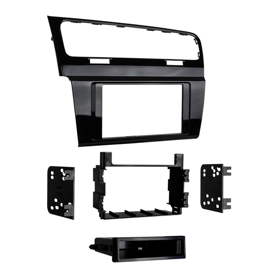
KIT COMPONENTS
• A)
Radio trim panel
• B) Radio housing • C) Radio brackets • D) Pocket • E) (8) #8 x 3/8" Phillips screws
A
B
WIRING & ANTENNA CONNECTIONS (sold separately)
Wiring Harness: • XSVI-9006-NAV Antenna Adapter: • 40-EU56
99-9013HG
C
D
TOOLS REQUIRED
• Panel removal tool • Phillips screwdriver
• Euro radio removal keys (2 sets)
Metra part number: 86-9001
E
CAUTION: Metra recommends disconnecting the negative battery
terminal before beginning any installation, unless the vehicle
manufacturer recommends against so. Please check with your
local Dealership for more information. All accessories, switches,
climate controls panels, and especially air bag indicator lights
must be connected before reconnecting the battery or cycling
the ignition. Also, do not remove the factory radio with the key
in the on position, or the vehicle running. It would be best to
remove the key from the ignition and then wait a few seconds
before removing the factory radio.
Advertisement
Table of Contents

Related Manuals for Metra Electronics 99-9013HG


Summary of Contents for Metra Electronics 99-9013HG
- Page 1 Installation instructions for part 99-9013HG Volkswagen Golf 2015-up 99-9013HG KIT FEATURES • ISO DIN radio provision with pocket • ISO DDIN radio provision • Painted high-gloss black TOOLS REQUIRED • Panel removal tool • Phillips screwdriver KIT COMPONENTS • Euro radio removal keys (2 sets) •...
- Page 2 99-9013HG Dash Disassembly 1. Open the door below the climate control panel. (Figure A) 2. Unclip and remove the climate control trim panel. (Figure B) 3. Remove and unplug the passenger airbag hazard switch assembly. 4. Unclip the vent/display trim bezel.
- Page 3 99-9013HG Dash Disassembly 5. Unclip and remove the vents from the factory trim panel and save for kit assembly. (Figure D) 6. Remove the factory radio display using (2) sets of euro radio removal keys (top and bottom). (Figure E) 7.
- Page 4 99-9013HG Kit Assembly ISO DIN radio provision with pocket 5. Screw the pocket into the radio and bracket assembly using 1. Cut and remove the (2) plastic (4) #8 x 3/8” screws supplied with shaded areas from the sub dash.
- Page 5 (4) #8 x 3/8” screws supplied with the kit. (Figure E) 8. Insert the factory vent assembly into the 99-9013HG radio trim panel. (Figure F) 9. Reassemble the dash in the reverse order of disassembly, using the 99-9013HG radio trim panel.
- Page 6 99-9013HG Kit Assembly ISO DDIN radio provision 4. CAUTION! The airbag light must be 1. Cut and remove the (2) plastic plugged in before the ignition is shaded areas from the sub dash. cycled on. Failure to do so will (Figures A, B).
- Page 7 (4) #8 x 3/8” screws supplied with the kit. (Figure D) 6. Insert the factory vent assembly into the 99-9013HG radio trim panel. (Figure E) 7. Reassemble the dash in the reverse order of disassembly, using the 99-9013HG radio trim panel.
Need help?
Do you have a question about the 99-9013HG and is the answer not in the manual?
Questions and answers