Sign In
Upload
Manuals
Brands
Allen-Bradley Manuals
Controller
1336 IMPACT
Allen-Bradley 1336 IMPACT Manuals
Manuals and User Guides for Allen-Bradley 1336 IMPACT. We have
3
Allen-Bradley 1336 IMPACT manuals available for free PDF download: Troubleshooting Manual, Quick Start Manual, Selection Manual
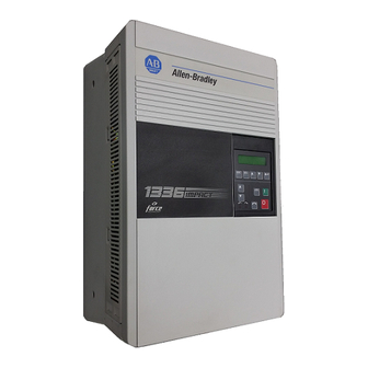
Allen-Bradley 1336 IMPACT Troubleshooting Manual (132 pages)
Adjustable Frequency AC Drive (Series A)
Brand:
Allen-Bradley
| Category:
Controller
| Size: 2.74 MB
Table of Contents
Table of Contents
6
Manual Objective
10
Safety Precautions
10
Who Should Use this Manual
10
Electrostatic Discharge Precautions
11
1336 IMPACT Product Identification
12
Drive Nameplate Location
12
Drive and Option Identification
13
1336 IMPACT Drive Catalog Numbers
13
Drive Rating Qualifications
18
Enclosure Type
18
Conventions
19
Auxiliary Interlock
19
Bit
19
Check
19
Connector
19
Default
19
Enable Input
20
False
20
Jumper
20
L Option Board
20
Not External Fault Input
20
Parameter
20
Press
21
True
21
Related Publications
21
Chapter 1 Control Logic Wiring and Adapters
22
Chapter Objectives
22
Chapter Overview
22
L Option Board
23
L Option Board Jumpers
24
Available Inputs
25
Local Programming
26
Human Interface Module (HIM)
30
Description
30
Removing the HIM
31
HIM Operation
33
Graphic Programming Terminal
33
GPT Description
33
Drivetools
34
Control Firmware Function
34
Chapter 2 Troubshooting and Error Codes
36
Chapter Objectives
36
Fault/Warning Handling
36
Viewing the Fault and Warning Queues on the HIM
38
What Are the Fault Descriptions
39
Diagnostic Procedures by Symptom
49
Start up Troubleshooting Procedures
53
Miscellaneous Troubleshooting Procedures
53
Encoderless Troubleshooting Procedures
55
Chapter 3 Disassembly and Access
56
Procedures
56
Chapter Objectives
56
Disassembly and Access Overview
56
Electrostatic Discharge Precautions
56
Tools
57
Fastener Torque Specifications
58
Torque Sequence
58
Two-Point Mounting
58
Four-Point Mounting
58
Torque Specifications
59
Disassembly and Access Procedures
60
Opening the Drive Enclosure
60
Removal
61
Installation
61
Removing L Option Board
62
Removal
63
Installation
63
Removing the Main Control Board Mounting Plate
64
Removal
64
Installation
65
Removing the Main Control Board
66
Removal
66
Installation
67
Removing the Precharge Board
68
Removal
68
Installation
69
Removing the Gate Driver Board
70
Removal
70
Installation
71
Removing the Snubber Board
72
Removal
72
Installation
74
Accessing Chassis Power Components
74
Chapter 4 Component Test Procedures
76
Chapter Objectives
76
Component Test Overview
76
Electrostatic Discharge Precautions
77
Tools
77
Test 1 - Testing Input Rectifier SCR1
78
Test 2 - Testing the Bus Capacitor Bank
80
Test 3 - Testing Power Modules PM1 - PM3
83
Test 4 - Testing Bus Fuse F1
85
Test 5 - Testing the Gate Driver Board
87
Test 6 - Testing the Precharge Board
89
Test 7 - Testing the Thermistor
91
Chapter 5 Part Replacement Procedures
94
Chapter Objective
94
Part Replacement Overview
94
Safety Precautions
94
Electrostatic Discharge Precautions
94
Tools
95
Major Component Replacement
95
Detailed Product Identification
95
Ground Sense CT
97
Removal
97
Installation
99
Bus Fuse F1
100
Removal
101
Installation
101
Thermistor
102
Removal
102
Installation
103
Power Modules PM1 - PM3
104
Removal
104
Installation
105
Input Rectifier SCR1
106
Removal
106
Installation
107
Fan
108
Removal
109
Installation
110
DC Bus Inductor L1
111
Removal
112
Installation
113
Advertisement
Allen-Bradley 1336 IMPACT Quick Start Manual (68 pages)
Brand:
Allen-Bradley
| Category:
DC Drives
| Size: 2.39 MB
Allen-Bradley 1336 IMPACT Selection Manual (26 pages)
Digital AC Drives in CENTERLINE Motor Control Centers
Brand:
Allen-Bradley
| Category:
Controller
| Size: 0.34 MB
Table of Contents
Table of Contents
3
About this Publication
5
General Product Description
5
Plug-In Drive Units
6
Frame-Mounted Drive Units
6
Roll-Out Drive Units
7
Preface
5
Documentation
7
UL Certification
7
Chapter 1 Powerflex® 700 and 700S Product Selection
9
Catalog Number Explanation
9
Frame Selection
10
Drive Unit Options
11
Catalog Number Explanation
15
Frame Selection
16
Drive Unit Options
17
Chapter 2 1336 PLUS™ Variable Frequency, 1336 PLUS™ II, 1336 FORCE - Vector Control, 1336 IM-
21
Chapter 3 Motor Control Center Vertical Sections
21
Features and Modifications
21
Chapter 4 Busbar Splice Kits
23
Understanding Busbar Splice Catalog Numbers
23
Determining Splice Kit Catalog Numbers
23
Splice Kit Catalog Numbers
23
Power Bus Splice Kit Catalog Numbers
23
Control Bus Splice Kit Catalog Numbers
24
PE/TE Bus Splice Kit Catalog Numbers
24
Advertisement
Advertisement
Related Products
Allen-Bradley 1336-RFB-7-AA
Allen-Bradley 1336-RFB-16-AA
Allen-Bradley 1336-RFB-7-A
Allen-Bradley 1336-RFB-16-A
Allen-Bradley 1336-RFB-30-A
Allen-Bradley 1336-RFB-30-A4
Allen-Bradley 1336-RFB-27-B
Allen-Bradley 1336-RFB-48-B
Allen-Bradley 1336-RFB-150-D
Allen-Bradley 1336-RFB-80-C
Allen-Bradley Categories
Control Unit
Controller
I/O Systems
Power Supply
Switch
More Allen-Bradley Manuals
Login
Sign In
OR
Sign in with Facebook
Sign in with Google
Upload manual
Upload from disk
Upload from URL