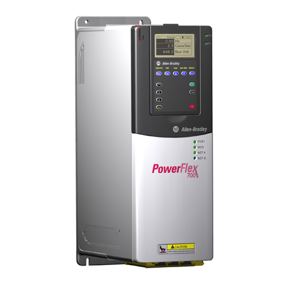
Allen-Bradley PowerFlex 700 Installation Instructions Manual
With vector control option custom firmware
Hide thumbs
Also See for PowerFlex 700:
- Quick start manual ,
- User manual (198 pages) ,
- Installation instructions manual (96 pages)
Advertisement
Quick Links
Installation Instructions
PowerFlex 700 with Vector Control Option
Custom Firmware
"BA" Option - Pump Off Function
Series B
Topic
Custom Firmware Overview
Pump Off Setup
Initializing the Pump Stroke Position
Custom Firmware Parameters
New Selection for Existing Parameters
Test Points
ATTENTION: The custom firmware is designed for a specific application and load condition. It differs from the
standard PowerFlex 700 Vector Control product offering and must be installed and run only under this custom
application. Attempting to run this custom firmware under any other type of application can result in
unpredictable and/or hazardous conditions.
ATTENTION: The drive contains parts and assemblies that are sensitive to electrostatic discharge (ESD). Static
control precautions are required when installing, testing, servicing, or repairing parts and assemblies.
Component damage can result if ESD control procedures are not followed. If you are not familiar with static
control procedures, refer to Guarding Against Electrostatic Damage Data Sheet, publication 8000-4.5.2, or
other applicable ESD protection handbook.
The PowerFlex 700 sensorless pump off function is an enhancement to the basic pumpjack oil
well application. The pump off function detects when the fluid level in a well drops.
Programming then determines if the drive slows down or stops pumping. The low level detection
is accomplished by an algorithm that utilizes dynamic motor data, thereby removing the need for
external sensors. Productivity can be increased by detecting a low well condition and pumping at
a slower rate during the "pump off " condition rather than simply running the pump on a timer.
Page
2
3
3
5
9
9
Advertisement

Summary of Contents for Allen-Bradley PowerFlex 700
-
Page 1: Installation Instructions
ATTENTION: The custom firmware is designed for a specific application and load condition. It differs from the standard PowerFlex 700 Vector Control product offering and must be installed and run only under this custom application. Attempting to run this custom firmware under any other type of application can result in unpredictable and/or hazardous conditions. - Page 2 PowerFlex 700 firmware. For additional drive information including the basic pumpjack oil well parameter descriptions and other standard firmware parameters, refer to the PowerFlex 700 AC Drives – Frames 0…10 User Manual, Vector Control Firmware 4.001 and Up, publication 20B-UM002.
- Page 3 PowerFlex 700 with Vector Control Option Custom Firmware 3 Pump Off Setup Follow these steps to set up the pump off function. 1. Set parameter 53 [Motor Cntl Sel] to 4, “FVC Vector.” 2. Set parameter 641 [OilWell Pump Sel] to 1, “Pump Jack.”...
- Page 4 4 PowerFlex 700 with Vector Control Option Custom Firmware Pump Stroke Position Initialization Steps (cont.) Step Parameter Description [Pump Off Control] • Disabled - pump off control is not active. • Baseline Set - Uses a torque baseline created when the drive is first run (first ten cycles).
- Page 5 PowerFlex 700 with Vector Control Option Custom Firmware 5 Custom Firmware Parameters Advanced Parameter View must be selected (parameter 196 [Param Access Lvl] set to 1, “Advanced”). Parameters 692 through 699 provide various metering points for the function. Refer to pages for descriptions.
- Page 6 6 PowerFlex 700 with Vector Control Option Custom Firmware Custom Firmware Parameters (cont.) Parameter Name and Description Values See User Manual for symbol descriptions 683 [Pump Off Config] Default: “Automatic” Sets the torque data to use for Pump Off control.
- Page 7 PowerFlex 700 with Vector Control Option Custom Firmware 7 Custom Firmware Parameters (cont.) Parameter Name and Description Values See User Manual for symbol descriptions 687 [Pump Off Speed] Default: 20.0% Sets the percent drop in speed from the commanded speed Min/Max: 0.0/100.0%...
- Page 8 8 PowerFlex 700 with Vector Control Option Custom Firmware Custom Firmware Parameters (cont.) Parameter Name and Description Values See User Manual for symbol descriptions 690 [Pump Off Status] Read Only Status of the Pump Off function. 1 = Condition True...
- Page 9 For parameter 361…366 [Digital InX Sel], added a new selection: 61, “Baseline Dis”. Test Points The following test points are provided for pump diagnostics. Refer to the PowerFlex 700 AC Drives – Frames 0…10 User Manual, Vector Control Firmware 4.001 and Up, publication 20B-UM002, for instructions to access the test points.
- Page 10 10 PowerFlex 700 with Vector Control Option Custom Firmware Test Points (cont.) Test Point Description Baseline torque, calculated on first run or when commanded speed is changed Pump off trip level, x100 Pump off detector current value, x100 Speed used during pump off...
- Page 11 PowerFlex 700 with Vector Control Option Custom Firmware 11 Test Points (cont.) Test Point Description Counter for position reconnect Pump status: bit 13 = Pump off disable input active bit 12 = 0 = Position, 1 = Cycle torque used...
- Page 12 (0…23) Stroke count per hour, updated once per hour. “0” is the most current. (0…23) Downstroke or cycle torque, updated once per hour. “0” is the most current. Allen-Bradley, Rockwell Software, PowerFlex, and Rockwell Automation are trademarks of Rockwell Automation, Inc. Trademarks not belonging to Rockwell Automation are property of their respective companies.


Need help?
Do you have a question about the PowerFlex 700 and is the answer not in the manual?
Questions and answers