Table of Contents
Advertisement
Quick Links
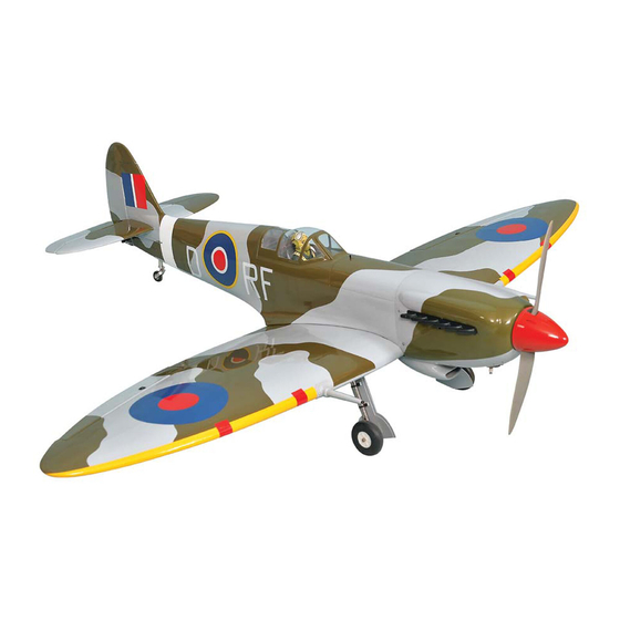
SPITFIRE
GP/EP Size 30cc SCALE 1:6 ¼ ARF
SPECIFICATION
- Wingspan: 1800mm (70.8in)
- Length: 1572mm (61.9 in)
- Flying weight: 5800-6200g
- Wing area: 53.4 dm2
- Wing loading: 108g/dm2
- Wing type: Naca airfoils
- Covering type: Genuine ORACOVER®
- Gear type: Retract gear With CNC Suspension
Metal Struts and spring Tail gear (included)
- Spinner size: Plastic 95mm (included)
- Radio: 6 channel minimum (not included)
- Servo: 7 standard hi-torque servo: 2 aileron; 2 flap;
1 elevator; 1 rudder; 1 throttle; 2 retract gear
(Futaba S3170G) or 2 electric retract (not included)
- Recommended receiver battery:
4.8-6V / 2000mAh NiMH (not included)
- Servo mount: 21mm x 42 mm
- Propeller: suit with your engine
Instruction Manual
- Engine: 30 cc gas engine (not included)
- Motor: brushless outrunner 1600-2200 W,
450 KV (not included)
- Gravity CG: 120 mm (4.7 in) Back from the
leading edge of the wing, at the fuselage
- Control throw Ailerons: Low: 11mm up/down,
10% expo; High: 13mm up/down, 10% expo
- Control throw Elevators: Low: 11mm up/down,
12% expo; High: 13mm up/down, 12% expo
- Control throw Rudder: Low: 30mm right/left,
15% expo; High: 40mm right/left, 15% expo
- Control throw flap : Mid : 15mm down;
Landing : 20mm down
- Experience level: Intermediate
- Plane type: Scale Military
RECOMMENDED MOTOR AND BATTERY SET UP
- Motor: RIMFIRE .120 (not included)
- Lipo cell: 5-6 cells / 5500 – 6000mAh (not included)
- Esc: 120-160A (not included)
GP
EP
version
version
Advertisement
Table of Contents

Related Manuals for Phoenix Model PH151


Summary of Contents for Phoenix Model PH151
- Page 1 Instruction Manual version version SPITFIRE GP/EP Size 30cc SCALE 1:6 ¼ ARF SPECIFICATION - Engine: 30 cc gas engine (not included) - Wingspan: 1800mm (70.8in) - Motor: brushless outrunner 1600-2200 W, - Length: 1572mm (61.9 in) 450 KV (not included) - Flying weight: 5800-6200g - Gravity CG: 120 mm (4.7 in) Back from the - Wing area: 53.4 dm2...
-
Page 2: Tools And Supplies Needed
SPITFIRE Instruction Manual TOOLS AND SUPPLIES NEEDED. The painted and plastic parts used in this kit are fuel proof. However, they are not tolerant of many harsh chemicals including the following: paint thinner, C/A • Medium C/A glue glue accelerator, C/A glue debonder and acetone. Do •... -
Page 3: Installing The Ailerons
SPITFIRE Instruction Manual INSTALLING THE AILERONS TEMPORARY PIN 1. Test fit the ailerons to the wing with the hinges. TO KEEP HINGE If the hinges don’t remain centered, stick a pin CENTERED through the middle of the hinge to hold it in position. - Page 4 SPITFIRE Instruction Manual 4. Using the thread as a guide and using masking INSTALLING THE AILERONs AND FLAPs tape, tape the servo lead to the end of the thread: carefully pull the thread out. When you SERVOS have pulled the servo lead out, remove the masking tape and the servo lead from the 1.
- Page 5 SPITFIRE Instruction Manual 2x10mm 2x10mm Warning! Set all scerws securely. If they come off during flight you will lose control of your aircraft! 2x10mm Cut away film only here. Tie the string. Pull out servo cord with string. Must be purchased separately! Cut off shaded portion...
-
Page 6: Installing The Ailerons And Flaps Linkages
SPITFIRE Instruction Manual INSTALLING THE AILERONs AND FLAPs LINKAGES 3 x 15mm Cap Screw 3 x 25mm Cap Screw 2 x 10mm Screw Flap Aileron < Bottom view > Neutral 2x10mm Apply threadlocker (screw cement). Cut off shaded portion Assemble left and right Cut off excess. -
Page 7: Installing The Main Landing Gear
SPITFIRE Instruction Manual Flap Aileron < Bottom view > Assemble left and right sides the same way INSTALLING THE MAIN LANDING GEAR 3 x 10mm Button Screw 5 x 40mm Cap Screw 5mm Collar 4x4mm Set Screw Bend 90 Mark the spot to attach. - Page 8 SPITFIRE Instruction Manual Apply threadlocker (screw cement). 3x10mm 3x10mm Assemble left and right sides the same way Apply instant glue (CA glue, super glue).
- Page 9 SPITFIRE Instruction Manual < Wheel well > 3 x 20mm TP Screw 2 x 10mm TP Screw Assemble left and right sides the same way Apply epoxy glue Cut off shaded portion Pay close attention here!
- Page 10 SPITFIRE Instruction Manual 3x20mm 3x20mm Temporarily remove. Tighten the 2 nuts properly. Assemble left and right sides the same way Ensure smooth, non-binding Apply threadlocker movement when assembling (screw cement).
- Page 11 SPITFIRE Instruction Manual < Retract and the gear is Closed. > < Retract and the gear is Opened. > 2x10mm Apply epoxy glue Assemble left and right sides the same way...
- Page 12 SPITFIRE Instruction Manual SECURE The Wing To The Fuselage 6 x 60mm Plastic Screw Attach the wings to the fuselage and secure the wing panels. 6x60mm Cut off shaded portion...
-
Page 13: Horizontal Stabilizer Installation
SPITFIRE Instruction Manual HORIZONTAL STABILIZER INSTALLATION When you are sure that everything is aligned correctly, mix up a generous amount of 30 minute epoxy. Apply a thin layer to the bottom and to the 1. Using a modeling knife, cut away the covering top of the stabilizer mounting area and to the from the fuselage for the stabilizer and remove it. - Page 14 SPITFIRE Instruction Manual Cut off shaded portion INSTALLing rudder Apply instant glue (CA glue, super glue). Apply epoxy glue...
-
Page 15: Installing The Rudder Linkages
SPITFIRE Instruction Manual INSTALLING THE RUDDER LINKAGES 5. Thread the metal connector to the link ball. 6. Center the rudder servo using the radio and The rudder is controlled by two metal cables. install the servo arm. Attach the metal clevis to Install the rudder linkages and cables as below. -
Page 16: Installing The Tail Wheel
SPITFIRE Instruction Manual Set all screws securely. If they come off during flight you will lose control of your aircraft! Pay close attention here Must be purchased separately! Rudder servo Cut off shaded portion INSTALLing The tail WHEEL Pay close attention Cut off shaded portion... - Page 17 SPITFIRE Instruction Manual 25mm Linkage Wire 4x4mm Close or clamp pipe to fix position.
- Page 18 SPITFIRE Instruction Manual Hatch Open and close...
- Page 19 SPITFIRE Instruction Manual 90 Degree Cable rod Cable rod Cut off excess. Rudder Linkages Tail Wheel Rudder Linkages...
-
Page 20: Installing The Elevator Pushrod
SPITFIRE Instruction Manual INSTALLING THE ELEVATOR PUSHROD 7. Attach nylon clevis to the control horn and secure it . 1. Locate the pushrod exit slot on the right side and left side of the fuselage. It is located 8. Locate one nylon servo arm, and using wire slightly ahead and below the horizontal cutters, remove all but one of the arms. - Page 21 SPITFIRE Instruction Manual approx. 13mm Elevator Servo Elevator Servo Cut off shaded portion Cut off excess. Must be purchased separately! Pay close attention here...
-
Page 22: Installing The Fuel Tank
SPITFIRE Instruction Manual INSTALLING THE Fuel Tank 1. The stopper has been pre-assembled at the 6. When satisfied with the alignment of the stopper factory. assembly tighten the 3mm x 20mm machine screw until the rubber stopper expands and 2. Using a modeling knife, cut one length of silicon seals the tank opening. -
Page 23: Installing The Engine
SPITFIRE Instruction Manual 3x10mm White glue Refer to engin’s instruction manual and set up piping. INSTALLING THE ENGINE 5x100mm Cap Screw May be you also need to trim some 3 x 300mm Choke rod wood from the tri-angle wood for 12x60mm Aluminum the installation is easy. - Page 24 SPITFIRE Instruction Manual Choke rod Silicone Bend 90 16x5mm DLE 30CC 5x100mm 12x60mm 5x100mm Throttle Lever Choke Lever DLE 30CC Silicone Apply threadlocker (screw cement). Must be purchased separately!
- Page 25 SPITFIRE Instruction Manual DLE 30CC Electronic Ignition Zip tie Foam Pad Must be purchased separately!
-
Page 26: Installing The Throttle
SPITFIRE Instruction Manual INSTALLING THE THROTTLE 1. Plug the throttle servo into the receiver and turn on the radio system. Check to ensure that the throttle servo output shaft is moving in the correct direction. When the throttle stick is moved forward Silicone from idle to full throttle, the throttle barrel should also open and close using this motion. -
Page 27: Mounting The Cowl
SPITFIRE Instruction Manual MOUNTING THE COWL 4. While holding the cowl firmly in position, drill 1. Remove the muffler and needle valve assembly four 1,6mm pilot holes through both the cowl from the engine. Slide the fiberglass cowl over the and the side edges of the firewall. - Page 28 SPITFIRE Instruction Manual Washer Trim the cowling so it will match your engine 3x15mm Cut off shaded portion...
- Page 29 SPITFIRE Instruction Manual Hatch Must be purchased separately!
-
Page 30: Installing The Spinner
SPITFIRE Instruction Manual INSTALLING THE SPINNER Install the spinner back-plate, propeller and spinner cone. The spinner cone is held in place using two screws. The propeller should not touch any part of the spinner cone. If it dose, use a sharp modeling knife and carefully trim away the spinner cone where the propeller comes in contact with it. - Page 31 SPITFIRE Instruction Manual Must be purchased separately! Cut off shaded portion Must be purchased separately!
-
Page 32: Installing The Electric Motor ( Ep Version )
SPITFIRE Instruction Manual INSTALLING THE ELECTRIC MOTOR ( EP VERSION ) 4 x 35mm Cap Screw 4mm Washer 4mm Spring Washer 10x15mm Aluminum 5mm Washer 4x35mm 10x15mm 4x35mm 16x5mm 5x100mm 12x60mm 5x100mm White glue Apply threadlocker (screw cement). Must be purchased separately! - Page 33 SPITFIRE Instruction Manual Battery Cord Velcro Battery Must be purchased separately! < Check the motor rotation > When rotating clock wise, change the connection of 2 wires. Electric Speed Controller Follow instruction manual of Motor and ESC. Must be purchased separately!
-
Page 34: Control Throws
SPITFIRE Instruction Manual BALANCING 3. Turn the airplane upside down. Place your fingers 1. It is critical that your airplane be balanced correctly. on the masking tape and carefully lift the plane. Improper balance will cause your plane to lose 4. -
Page 35: Flight Preparation Pre Flight Check
SPITFIRE Instruction Manual FLIGHT PREPARATION PRE FLIGHT CHECK 1. Completely charge your transmitter and receiver batteries before your first day of flying. 2. Check every bolt and every glue joint in your plane to ensure that everything is tight and well bonded. - Page 36 SPITFIRE Instruction Manual Main Gear Dimensional Detail 160.0 33.5 16.8...
- Page 37 SPITFIRE Instruction Manual Tail Gear Dimensional Detail 14.5 3x10mm 3x15mm(TP) 10x15mm 4x35mm 2x13mm 16x5mm 12x60mm 3x12mm(TP) 5x100mm...
- Page 38 3x20mm 3x25mm 3x15mm 3x20mm 2x10mm(TP) 2x10mm 2x10mm(TP) 3x35mm 3x10mm 3x20mm(TP) 3x15mm 2x10mm 3x25mm 3x20mm(TP) 3x10mm 2x10mm(TP) 2x10mm(TP)
- Page 39 I/C FLIGHT WARNINGS Always operate in open areas, away Keep all onlookers (especially small from factories, hospitals, schools, THE PROPELLER IS DANGEROUS children and animals) well back from buildings and houses etc. NEVER fly Keep fingers, clothing (ties, shirt the area of operation. This is a flying your aircraft close to people or built sleeves, scarves) or any other loose aircraft, which will cause serious...
- Page 40 I/C FLIGHT GUIDELINES Operate the control sticks on the When ready to fly, first extend the transmitter and check that the control transmitter aerial. surfaces move freely and in the ALWAYS land the model INTO the CORRECT directions. wind, this ensures that the model lands at the slowest possible speed.
Need help?
Do you have a question about the PH151 and is the answer not in the manual?
Questions and answers