Table of Contents
Advertisement
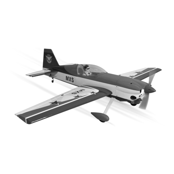
GP/EP size .46-.55 SCALE 1:5 ARF
SPECIFICATION
- Wingspan: 1472mm (57.9 in)
- Length: 1335mm (52.5 in)
- Flying weight: 2800-3000 gr
- Wing area: 38.5 dm2
- Wing loading: 76g/dm2
- Wing type: Naca airfoils
- Covering type: Genuine ORACOVER®
- Gear type: Aluminum Hi-grade for main
gear and spring wire for tail gear (included)
- Spinner size: Plastic 58mm (included)
- Radio: 4 channel minimum (not included)
- Servo: 5 standard servo: 2 aileron;
1 elevator; 1 rudder; 1 throttle (not included)
- Recommended receiver battery:
4.8-6V / 800-1200mAh NiMH (not included)
- Servo mount: 21mm x 42 mm
- Propeller: suit with your engine
Instruction Manual
M X S
- Engine: .46-.55 / 2-stroke or .52/4-stroke
glow engine (not included)
- Motor: brushless outrunner 1000-1400 W,
480 KV (not included)
- Gravity CG: 90 mm (3.5 in) Back from the
leading edge of the wing, at the fuselage
- Control throw Ailerons: Low: 8mm up/down,
10% expo; High: 10mm up/down, 10% expo
- Control throw Elevators: Low: 8mm up/down,
12% expo; High: 10mm up/down, 12% expo
- Control throw Rudder: Low: 25mm right/left,
15% expo; High: 40mm right/left, 15% expo
- Experience level: Intermediate
- Plane type: Scale Aerobatic
RECOMMENDED MOTOR AND BATTERY SET UP
- Motor: RIMFIRE .46-.55 (not included)
- Lipo cell: 6 cells / 4000 – 5500mAh (not included)
- Esc: 50-80A (not included)
Advertisement
Table of Contents

Related Manuals for Phoenix Model MXS


Summary of Contents for Phoenix Model MXS
- Page 1 Instruction Manual M X S GP/EP size .46-.55 SCALE 1:5 ARF SPECIFICATION - Engine: .46-.55 / 2-stroke or .52/4-stroke - Wingspan: 1472mm (57.9 in) glow engine (not included) - Length: 1335mm (52.5 in) - Motor: brushless outrunner 1000-1400 W, - Flying weight: 2800-3000 gr 480 KV (not included) - Wing area: 38.5 dm2 - Gravity CG: 90 mm (3.5 in) Back from the...
-
Page 2: Safety Precaution
This will assure proper assembly. The TEMPORARY PIN MXS GP/EP size .46-.55 SCALE 1:5 ARF is hand TO KEEP HINGE made from natural materials, every plane is unique CENTERED and minor adjustments may have to be made. -
Page 3: Installing The Aileron Servos
Instruction Manual MXS size .46-.55 INSTALLING THE AILERON SERVOS 5. Place the aileron servo tray / hatch into the servo box on the bottom of the wing and drill 1. Install the rubber grommets and brass eyelets 1,6mm pilot holes through the tray and the onto the aileron servo. -
Page 4: Installing The Aileron Linkages
Instruction Manual MXS size .46-.55 Silicone Tube RIGHT WRONG 3. Repeat step # 1 - # 2 to install the control horn on the opposite aileron. 9. Repeat step # 4 - # 8 to install the second INSTALLING THE AILERON LINKAGES aileron linkage. - Page 5 Instruction Manual MXS size .46-.55 2. Draw a center line onto the horizontal stabilizer. Remove the covering Draw a center line 6. When you are sure that everything is aligned 3. Check the fit of the horizontal stabilizer in its correctly, mix up a generous amount of 30 slot.
-
Page 6: Vertical Stabilizer Installation
Instruction Manual MXS size .46-.55 VERTICAL STABILIZER INSTALLATION 1. Using a modeling knife, remove the covering on the top of the fuselage for the vertical stabilizer. Remove Hinge the covering 4. Slide the vertical stabilizer back in place. Using a triangle, check to ensure that the vertical stabilizer is aligned 90 degree to the horizontal stabilizer. -
Page 7: Tail Wheel Installation
Instruction Manual MXS size .46-.55 TAIL WHEEL INSTALLATION INSTALLING THE WHEEL PANTS 1. Locate the wheel pants from the hardware bag. 1. Tail wheel set Mark the locations of the mounting axles onto the wheel pants. The locations of the two... -
Page 8: Installing The Engine
Instruction Manual MXS size .46-.55 INSTALLING THE ENGINE Locate the long piece of wire used for the throttle pushrod. One end of the wire has been pre-bend in to a "Z" bend at the factory. This "Z" bend should be inserted into the throttle arm of the engine when the engine is fitted onto the engine mount. -
Page 9: Installing The Stopper Assembly
Instruction Manual MXS size .46-.55 FUEL TANK installation INSTALLING THE STOPPER ASSEMBLY 1. The stopper has been pre-assembled at the factory. 2. Using a modeling knife, cut one length of silicon fuel line (the length of silicon fuel line is... -
Page 10: Installing The Elevator Pushrod
Instruction Manual MXS size .46-.55 8. Feed three lines through the fuel tank Throttle servo compartment and through the pre-drilled hole in Elevator servo the firewall. Pull the lines out from behind the engine, while guiding the fuel tank into place. -
Page 11: Installing The Rudder Pushrod
Instruction Manual MXS size .46-.55 7. Attach clevis to the third hole in the control Metal domino Elevator rod horn. Install a silicone tube on the clevis. Control horn elevator INSTALLING THE RUDDER PUSHROD 1. Locate the pushrod exit slot on the left of the fuselage. -
Page 12: Installing The Throttle
Instruction Manual MXS size .46-.55 INSTALLING THE THROTTLE 7. Attach clevis to the third hole in the control horn. Install a silicone tube on the clevis. 1. Install one adjustable metal connector through the third hole out from the center of one servo... -
Page 13: Installing The Receiver And Battery
Instruction Manual MXS size .46-.55 INSTALLING THE RECEIVER AND BATTERY 3. Slide the cowl back into place. Align the front of the cowl with the crankshaft of the engine. The front of the cowl should be positioned so the 1. Plug the servo leads and the switch lead into crankshaft is in the middle of the precut the receiver. -
Page 14: Lateral Balance
Instruction Manual MXS size .46-.55 LATERAL BALANCE After you have balanced a plane on the C.G. You should laterally balance it. Doing this will Aileron Control help the airplane track straighter. 5. Turn the airplane upside down. Attach one loop of heavy string to the engine crankshaft and one to the tail wheel wire. - Page 15 5. Check the receiver antenna. It should be fully extended and not coiled up inside the fuselage. 6. Properly balance the propeller. We wish you many enjoyable flights with your plane and once again thank you for your choosing a Phoenix Model's products.
- Page 16 I/C FLIGHT GUIDELINES Operate the control sticks on the When ready to fly, first extend the transmitter and check that the control transmitter aerial. surfaces move freely and in the ALWAYS land the model INTO the CORRECT directions. wind, this ensures that the model lands at the slowest possible speed.
Need help?
Do you have a question about the MXS and is the answer not in the manual?
Questions and answers