
Related Manuals for Phoenix Model Pilatus-PC21


Summary of Contents for Phoenix Model Pilatus-PC21
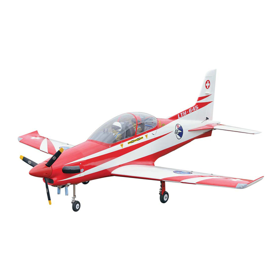
- Page 1 Instruction Manual 1543mm (60.75 in) 2010mm (79.13 inches) 5000gr - 7000gr 120 two stroke / 30cc 6 channel/ 9 servo...
-
Page 3: Kit Contents
Instruction Manual PILATUS - PC21 KIT CONTENTS: We have organized the parts as they come out of the box for better identification during assembly. We recommend that you regroup the parts in the same manner. This will ensure you have all of parts required before you begin assembly KIT CONTENTS MAIN GEAR ASSEMBLY AILERON CONTROL SYSTEM... -
Page 4: Tools And Supplies Needed
Instruction Manual PILATUS - PC21 TOOLS AND SUPPLIES NEEDED. PREPARATIONS Remove the tape and separate the ailerons • Medium C/A glue from the wing and the elevators from the stab. • 30 minute epoxy Use a covering iron with a covering sock on •... -
Page 5: Installing The Control Horns
Instruction Manual PILATUS - PC21 4. Using the thread as a guide and using masking tape, tape the servo lead to the end of the thread: carefully pull the thread out. When you have pulled the servo lead out, remove the masking tape and the servo lead from the thread. -
Page 6: Installing The Aileron Linkages
Instruction Manual PILATUS - PC21 INSTALLING THE AILERON LINKAGES 9. Repeat step # 4 - # 8 to install the second aileron linkage. After both linkages are completed, connect both of the aileron servo 1. Working with the aileron linkage for now, thread leads using a Y-harness you have purchased one nylon clevis at least 6 turns onto one of separately. - Page 7 Instruction Manual PILATUS - PC21 2. Remove the covering. 6. Secure the air retract to the wing. 3. Glue the plastic part by C.A glue. 7. Pull out the air tube through the wing section. Glue C.A 8. Trim the covering from the door gear. 4.
-
Page 8: Installing The Horizontal Stabilizer
Instruction Manual PILATUS - PC21 2. Remove the covering from the horizontal 10. Secure the wooden plate. stabilizer. Machine screw 3. Slide the joiner to the stabilizer. Aluminum Collar Dihedral brace 11. Secure the wing to the fuselage using the plastic screws. -
Page 9: Installing The Rudder
Instruction Manual PILATUS - PC21 INSTALLING THE RUDDER Installing the engine - Repeat step 1 - step 2 from the installing aileron for installing the rudder. Install with DLE 30 Engine 165mm Install with OS 120 two stroke Remove the covering Glue with epoxy - Glue two plate of wood into the rudder. - Page 10 Instruction Manual PILATUS - PC21 INSTALLING THE THROTTLE PUSHROD HOUSING FUEL TANK INSTALLING THE STOPPER ASSEMBLY 1. Place the engine into the engine mount and align it properly with the front of the cowling. The distance from the firewall to the front of the 1.
-
Page 11: Installing The Elevator Pushrod
Instruction Manual PILATUS - PC21 Blow through one of the lines to ensure the fuel Rudder servo Elevator servo lines have not become kinked inside the fuel tank compartment. Air should flow through easily. Do not secure the tank into place permanently until after balancing the airplane. -
Page 12: Installing The Rudder Pushrod
Instruction Manual PILATUS - PC21 6. Remove the covering from the slot, install the 8. Locate one nylon servo arm, and using wire control horn in place using C.A glue. cutters, remove all but one of the arms. Using a 2mm drill bit, enlarge the third hole out from the center to accommodate the elevator pushrod wire. - Page 13 Instruction Manual PILATUS - PC21 Remove the covering 7. Attach clevis to the hole in the control horn. 3. Working from inside the fuselage, slide the threaded end of the remaining pushrod down the inside of the fuselage until the pushrod reaches the exit slot.
-
Page 14: Mounting The Cowl
Instruction Manual PILATUS - PC21 MOUNTING THE COWL 1. Remove the muffler and needle valve assembly from the engine. Slide the fiberglass cowl over the engine. 2. Measure and mark the locations to be cut out for engine head clearance, needle valve, muffler,. -
Page 15: Installing The Nose Gear
Instruction Manual PILATUS - PC21 FINAL ASSEMBLY 3. Prepare the air tube. INSTALLING THE SPINNER The propeller should not touch any part of the 350mm spinner cone. If it dose, use a sharp modeling knife and carefully trim away the spinner cone where the propeller comes in contact with it. -
Page 16: Installing The Control Air System
Instruction Manual PILATUS - PC21 7. Install and secure the air retract to the fuselage. 2. The air valve. Machine screw 8. Slide the cable. 3. Attach the air valve to the servo. Metal connector Zip tie 9. Install two cable to the steering servo nose gear. 4. -
Page 17: Open And Close The Canopy
Instruction Manual PILATUS - PC21 OPEN AND CLOSE THE CANOPY BALANCING 1. It is critical that your airplane be balanced correctly. Improper balance will cause your plane to lose control and crash. THE CENTER OF GRAVITY IS LOCATED Screw 150mm BACK FROM THE LEADING EDGE OF THE WING, AT THE FUSELAGE. -
Page 18: Control Throws
Instruction Manual PILATUS - PC21 CONTROL THROWS 1. We highly recommend setting up a plane using the control throws listed. 2. The control throws should be measured at the widest point of each control surface. 3. Check to be sure the control surfaces move in the correct directions. - Page 19 I/C FLIGHT WARNINGS Always operate in open areas, away Keep all onlookers (especially small from factories, hospitals, schools, THE PROPELLER IS DANGEROUS children and animals) well back from buildings and houses etc. NEVER fly Keep fingers, clothing (ties, shirt the area of operation. This is a flying your aircraft close to people or built sleeves, scarves) or any other loose aircraft, which will cause serious...
- Page 20 I/C FLIGHT GUIDELINES Operate the control sticks on the When ready to fly, first extend the transmitter and check that the control transmitter aerial. surfaces move freely and in the ALWAYS land the model INTO the CORRECT directions. wind, this ensures that the model lands at the slowest possible speed.
Need help?
Do you have a question about the Pilatus-PC21 and is the answer not in the manual?
Questions and answers