Table of Contents
Advertisement
Quick Links
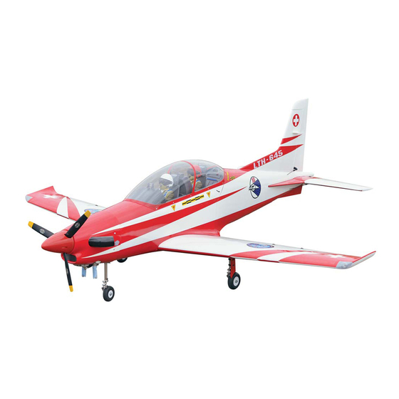
PC21 PILATUS
PC21 PILATUS
GP/EP SIZE .61-.91 or 15-20CC SCALE 1:6 ¼ ARF
SPECIFICATION
- Wingspan: 1450mm (57 in)
- Length: 1533mm (60.3 in)
- Flying weight: 4600-5000 g
- Wing area: 38.5 dm2
- Wing loading: 128g/dm2
- Wing type: Naca airfoils
- Covering type: Genuine ORACOVER®
- Gear type: Retract gear With CNC Suspension
Metal Struts (included)
- Spinner size: scale type 70mm (included)
- Radio: 6 channel minimum (not included)
- Servo: 8 standard servo: 2 aileron; 2 flap; 1 elevator;
1 rudder; 1steering nose; 1 throttle; and 3 retract
gear (Futaba S3170G) (not included)
- Recommended receiver battery:
4.8-6V / 2000 mAh NiMH (not included)
- Servo mount: 21mm x 42 mm
- Propeller: suit with your engine
Instruction Manual
- Engine: .61-.91 / 2-stroke glow engine or
15-20cc gas engine (not included)
- Motor: brushless outrunner 2200 W,
500 KV (not included)
- Gravity CG: 138 mm (5,4 in) Back from the
leading edge of the wing, at the fuselage
- Control throw Ailerons: Low: 8mm up/down,
10% expo; High: 10mm up/down, 10% expo
- Control throw Elevators: Low: 9mm up/down,
12% expo; High: 11mm up/down, 12% expo
- Control throw Rudder: Low: 20mm right/left,
15% expo; High: 30mm right/left, 15% expo
- Control throw Flap: 15-20 mm down
- Experience level: Intermediate
- Plane type: Scale Military
RECOMMENDED MOTOR AND BATTERY SET UP
- Motor: RIMFIRE .80 (not included)
- Lipo cell: 6 cells / 4000 – 5500mAh (not included)
- Esc: 60-100A (not included)
Advertisement
Table of Contents

Related Manuals for Phoenix Model PC21 PILATUS


Summary of Contents for Phoenix Model PC21 PILATUS
- Page 1 Instruction Manual PC21 PILATUS PC21 PILATUS GP/EP SIZE .61-.91 or 15-20CC SCALE 1:6 ¼ ARF SPECIFICATION - Engine: .61-.91 / 2-stroke glow engine or - Wingspan: 1450mm (57 in) 15-20cc gas engine (not included) - Length: 1533mm (60.3 in) - Motor: brushless outrunner 2200 W,...
-
Page 2: Tools And Supplies Needed
This will assure proper assembly. The TEMPORARY PIN PC21 PILATUS GP/EP SIZE .61-.91 or 15-20CC TO KEEP HINGE SCALE 1:6 ¼ ARF is hand made from natural CENTERED materials, every plane is unique and minor adjustments may have to be made. -
Page 3: Installing The Aileron Servos
Instruction Manual PC21 PILATUS INSTALLING THE AILERON SERVOS 5. Place the aileron servo tray / hatch into the servo box on the bottom of the wing and drill 1. Install the rubber grommets and brass eyelets 1,6mm pilot holes through the tray and the onto the aileron servo. -
Page 4: Installing The Aileron Linkages
Instruction Manual PC21 PILATUS 3. Repeat step # 1 - # 2 to install the control horn 2. Attach the clevis to the outer hole in the control on the opposite aileron. horn. Install a silicone tube on the clevis. -
Page 5: Installing The Landing Gear
Instruction Manual PC21 PILATUS 4. Install the servo retract gear. INSTALLING THE LANDING GEAR 5. One set of the landing gear. 1. Trim the plastic wheel well. 6. Attach the metal rod to the control horn. 2. Remove the covering from the bottom of the wing. - Page 6 Instruction Manual PC21 PILATUS 11. Install the adjustable servo connector to the 8. Secure the wheel. servo arm of the servo retract gear. Screw 12mm 9. Secure the axle. 12. Attach the rod to the servo arm. Screw 10. Secure the wooden wheel cover.
- Page 7 Instruction Manual PC21 PILATUS Gear Open Gear strut Servo retract Retract Servo arm Control Metal rod horn Adjustable servo connector Silicone tube M2 clevis 13. Secure the wood plate. Screw Screw 14. Make the same way for installing the second retract gear.
- Page 8 Instruction Manual PC21 PILATUS 2. Glue the wheel well by C.A glue. 6. Attach the metal rod to the nose retract. C.A glue 3. Install the steering nose servo into the servo tray 7. Secure the nose retract. in the fuselage.
- Page 9 Instruction Manual PC21 PILATUS 12. Secure the strut suspension to the retract 10. Connect the metal rod to the servo retract. and slide the two cable to the steering plate. Crimp 11. Install the two cable to the servo steering arm.
-
Page 10: Installing The Horizontal Stabilizer
Instruction Manual PC21 PILATUS INSTALLING THE HORIZONTAL STABILIZER 1. Using a modeling knife, cut away the covering from the fuselage for the stabilizer and remove it. Remover the covering 4. Remove the stabilizer. Using the lines you just drew as a guide, carefully remove the covering from between them using a modeling knife. -
Page 11: Engine Installation
Instruction Manual PC21 PILATUS 6. After the epoxy has fully cured, remove the masking tape or T-pins used to hold the stabilizer in place and carefully inspect the glue joints. Use more epoxy to fill in any gaps that were not filled previously and clean up the C.A glue... -
Page 12: Installing The Motor And Battery
Instruction Manual PC21 PILATUS - OS 15cc GT Screw INSTALLING THE MOTOR AND BATTERY Installing the electric motor This model can fly with electric, here is our recommended for set up the system. - Motor brushless: Rimfire .80 - Lipo cells: 6 cells / 4000 - 5500 mAh. -
Page 13: Installing The Stopper Assembly
Instruction Manual PC21 PILATUS INSTALLING THE STOPPER ASSEMBLY 8. Feed three lines through the fuel tank compartment and through the pre-drilled hole 1. The stopper has been pre-assembled at the in the firewall. Pull the lines out from behind the factory. -
Page 14: Installing The Elevator Pushrod
Instruction Manual PC21 PILATUS Rudder servo Elevator servo Control horn elevator INSTALLING THE ELEVATOR PUSHROD 1. Locate the pushrod exit slot on the right side and left side of the fuselage. It is located slightly ahead and below the horizontal stabilizer. -
Page 15: Installing The Rudder Pushrod
Instruction Manual PC21 PILATUS 12. With the elevator halves and elevator servo centered, carefully place a mark on the elevator pushrod wire where it crosses the hole in the servo arm. Control horn rudder 13. Using pliers, carefully make a 90 degree bend up at the mark made. -
Page 16: Installing The Throttle
Instruction Manual PC21 PILATUS Throttle servo Rudder rod MOUNTING THE COWL Open and close 1. Remove the muffler and needle valve assembly from the engine. Slide the fiberglass cowl over the engine. 2. Measure and mark the locations to be cut out for engine head clearance, needle valve, muffler,. - Page 17 Instruction Manual PC21 PILATUS Remover the covering Screw Switch C.A glue Receiver open and close the canopy Remover the Open and close covering GLUeing the expand part of horizontal and vertical stabilizer C.A glue...
-
Page 18: Lateral Balance
Instruction Manual PC21 PILATUS BALANCING 1. It is critical that your airplane be balanced correctly. Improper balance will cause your plane to lose control and crash. Remover the THE CENTER OF GRAVITY IS LOCATED covering 138mm (5.4 in) BACK FROM THE LEADING EDGE OF THE WING, AT THE FUSELAGE. -
Page 19: Flight Preparation Pre Flight Check
Instruction Manual PC21 PILATUS Ailerons : 8 mm up 8 mm down Elevator : 9 mm up 9 mm down Rudder : 20 mm right 20 mm left Flap : 15-20 mm down Aileron Control FLIGHT PREPARATION PRE FLIGHT CHECK 1. - Page 20 I/C FLIGHT GUIDELINES Operate the control sticks on the When ready to fly, first extend the transmitter and check that the control transmitter aerial. surfaces move freely and in the ALWAYS land the model INTO the CORRECT directions. wind, this ensures that the model lands at the slowest possible speed.
Need help?
Do you have a question about the PC21 PILATUS and is the answer not in the manual?
Questions and answers