Table of Contents
Advertisement
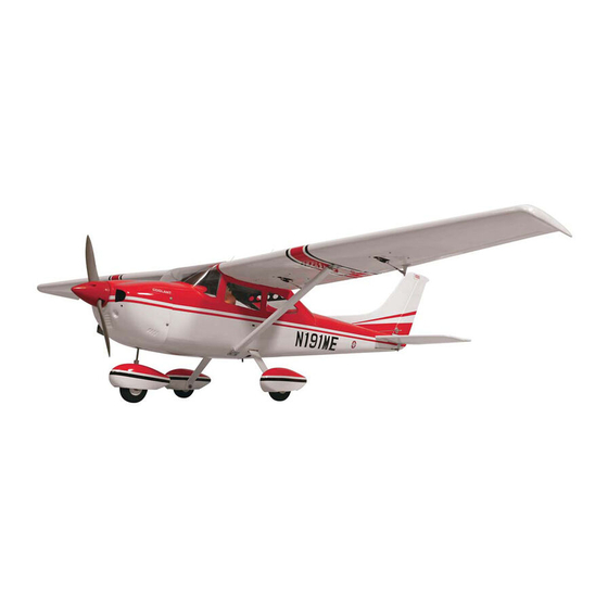
CESSNA SKYLANE 182
GP/EP SCALE 1:6 ½ ARF .46-.55
SPECIFICATION
- Wingspan: 1667mm (65.6in)
- Length: 1295mm (51 in)
- Flying weight: 3300 - 3400gr
- Wing area: 34.2 dm2
- Wing loading: 85g/dm2
- Wing type: Naca airfoils
- Covering type: Genuine ORACOVER®
- Gear type: Aluminum Hi-grade for main gear
and spring wire for nose gear (included)
- Spinner size: Plastic 58mm (included)
- Radio: 6 channel minimum (not included)
- Servo: 7 standard servo: 2 aileron; 2 flap; 1
elevator; 1 rudder; 1 throttle (not included)
- Recommended receiver battery:
4.8-6V / 800-1200mAh NiMH (not included)
- Servo mount: 21mm x 42 mm
- Propeller: suit with your engine
- Engine: .46-.55 / 2-stroke or .52/4-stroke
glow engine (not included)
Instruction Manual
- Motor: brushless outrunner 1000-1400 W,
- Gravity CG: 65-70 mm (2.6-2.8 in) Back from
- Control throw Ailerons: Low: 8mm up/down,
- Control throw Elevators: Low: 8mm up/down,
- Control throw Rudder: Low: 20mm right/left,
- Control throw Flaps: Mid: 15mm down;
- Experience level: Intermediate
- Plane type: Scale Civilian
RECOMMENDED MOTOR AND BATTERY SET UP
- Motor: RIMFIRE .46-.55 (not included)
- Lipo cell: 6 cells / 4000 – 5500mAh (not included)
- Esc: 50-80A (not included)
480 KV (not included)
the leading edge of the wing, at the fuselage
10% expo; High: 10mm up/down, 10% expo
12% expo; High: 10mm up/down, 12% expo
15% expo; High: 30mm right/left, 15% expo
Landing: 20mm down
Advertisement
Table of Contents

Related Manuals for Phoenix Model PH059


Summary of Contents for Phoenix Model PH059
- Page 1 Instruction Manual CESSNA SKYLANE 182 GP/EP SCALE 1:6 ½ ARF .46-.55 SPECIFICATION - Wingspan: 1667mm (65.6in) - Motor: brushless outrunner 1000-1400 W, - Length: 1295mm (51 in) 480 KV (not included) - Flying weight: 3300 - 3400gr - Gravity CG: 65-70 mm (2.6-2.8 in) Back from - Wing area: 34.2 dm2 the leading edge of the wing, at the fuselage - Wing loading: 85g/dm2...
-
Page 2: Tools And Supplies Needed
Instruction Manual CESSNA 182 TOOLS AND SUPPLIES NEEDED PREPARATIONS Remove the tape and separate the ailerons • Medium C/A glue from the wing and the elevators from the stab. • 30 minute epoxy Use a covering iron with a covering sock on •... -
Page 3: Installing The Aileron Servos
Instruction Manual CESSNA 182 INSTALLING THE AILERON SERVOS 5. Place the aileron servo tray / hatch into the servo box on the bottom of the wing and drill 1. Install the rubber grommets and brass eyelets 1,6mm pilot holes through the tray and the onto the aileron servo. -
Page 4: Installing The Aileron Linkages
Instruction Manual CESSNA 182 2. Attach the clevis to the outer hole in the control 3. Repeat step # 1 - # 2 to install the control horn horn. Install a silicone tube on the clevis. on the opposite aileron. 3. -
Page 5: Installing The Wing To The Fuselage
Instruction Manual CESSNA 182 INSTALLING THE WING TO THE FUSELAGE Attach the wings to the joiner tube and secure the wing panels to the fuselage. 4. Remove the stabilizer. Using the lines you just Screw drew as a guide, carefully remove the covering from between them using a modeling knife. -
Page 6: Vertical Stabilizer Installation
Instruction Manual CESSNA 182 Glue with epoxy 6. After the epoxy has fully cured, remove the 3. Now, remove the vertical stabilizer and using a masking tape or T-pins used to hold the modeling knife, carefully cut just inside the stabilizer in place and carefully inspect the glue marked lines and remove the film on both sides joints. -
Page 7: Installing The Wheel Pants
Instruction Manual CESSNA 182 4. The preinstalled wire steering pushrod has a Repeat step 1-2 from installing ailerons for factory made Z-Bend on the front end of it. installing rudder. Connect the nylon steering arm to this pushrod. The pushrod should be installed in the outermost hole in the steering arm. - Page 8 Instruction Manual CESSNA 182 After installing the wheel pant, apply a small drop of thin C/A to the bottom nut. 9. Repeat step # 1-8 to install the second wheel pant assembly. Drill MAIN GEAR INSTALLATION INSTALLING THE MAIN LANDING GEAR 1.
-
Page 9: Installing The Motor And Battery
Instruction Manual CESSNA 182 ENGINE INSTALLATION INSTALLING THE MOTOR AND BATTERY INSTALLING THE THROTTLE PUSHROD HOUSING Installing the electric motor 1. Install the engine mount into the fire wall using 4mm x 25mm screw. This model can fly with electric, here is our recommended for set up the system. -
Page 10: Installing The Stopper Assembly
Instruction Manual CESSNA 182 Atter confirming the direction (see front view of fuel tank). Insert and tighten the screw. 5. Test fit the stopper assembly into the tank. It may be necessary to remove some of the flashing around the tank opening using a modeling knife. -
Page 11: Installing The Elevator Pushrod
Instruction Manual CESSNA 182 3. Working from inside the fuselage, slide the threaded end of the pushrod until it reaches the exit slot. Carefully reach in with a small screw driver and guide the pushrod out of the exit slot. 4. -
Page 12: Installing The Rudder Pushrod
Instruction Manual CESSNA 182 6. Drill two holes through the rudder using the 9. Plug the elevator servo into the receiver and control horn as a guide and screw the control center the servo. Install the servo arm onto the horn in place. -
Page 13: Mounting The Cowl
Instruction Manual CESSNA 182 MOUNTING THE COWL Steering nose rod Rudder servo 1. Remove the muffler and needle valve assembly from the engine. Slide the fiberglass cowl over the engine. 2. Measure and mark the locations to be cut out for engine head clearance, needle valve, muffler. -
Page 14: Installing The Wing Strut
Instruction Manual CESSNA 182 Switch Receiver Cowl area cutout for proper airflow to carburetor. INSTALLING THE WING STRUT FINAL ASSEMBLY Secure the wing strut. INSTALLING THE SPINNER Install the spinner back-plate, propeller and spinner cone. The spinner cone is held in place using two 3mm x 20mm wood screws. -
Page 15: Installing The Antenna
Instruction Manual CESSNA 182 INSTALLING THE Antenna NOTE: Glue the Antenna. When flying with EP (Electric), please trim the leg (or foot) of pilot figure. (Or remove the pilot figure because they will touch the battery). open and close the Hatch C.A glue INSTALLING THE DOOR Open and close... -
Page 16: Lateral Balance
Instruction Manual CESSNA 182 5. We flew this model and here is our suggertion as shown below. A. This model fly with OS .46 or .55 (500gr). We had to add more 80gr lead to the cowl, the Aileron Control total weight is 3400gr, please see the picture as below.
Need help?
Do you have a question about the PH059 and is the answer not in the manual?
Questions and answers