Table of Contents
Advertisement
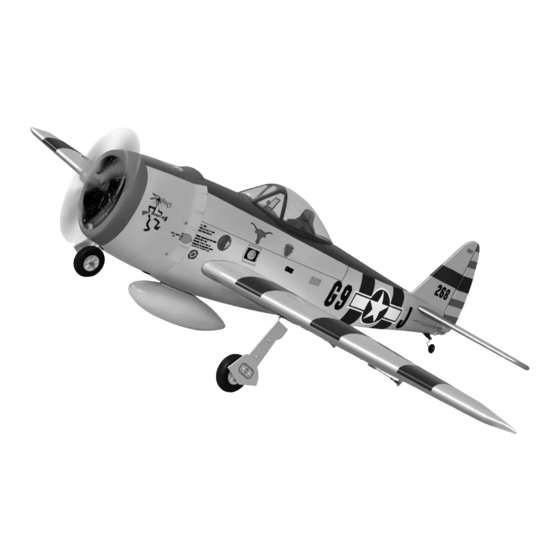
I n s t r u c t i o n M a n u a l
The Thunderbolt P47 was perhaps the greatest of world war II in terms of all -
round performance and capability. Phoenix Model has recreated a 2C - 60 class
engine (or 4c 91 class). It was designed with the latest laser cut technology and
every detail of the airplane has been carefully made. Quality wood construction -
Covered with ORACOVER (ultracote) Factory painted cowl - 95% almost ready
to fly. Most hardware included and all replacement parts are available.
Wing span: 1623mm (63.9 inches)
Length: 1410mm (55.51 inches)
Weight: 3500gr - 4000gr
g
Engine: 61 two stroke - 91 four stroke
Radio: 6 channel / 8 servos standard
Advertisement
Table of Contents

Related Manuals for Phoenix Model Thunderbolt P47


Summary of Contents for Phoenix Model Thunderbolt P47
- Page 1 I n s t r u c t i o n M a n u a l The Thunderbolt P47 was perhaps the greatest of world war II in terms of all - round performance and capability. Phoenix Model has recreated a 2C - 60 class engine (or 4c 91 class).
-
Page 3: Kit Contents
KIT CONTENTS: We have organized the parts as they come out of the box for better identification during assembly. We recommend that you regroup the parts in the same manner. This will ensure you have all of parts required before you begin assembly KIT CONTENTS AIR FRAME ASSEMBLIES AILERON CONTROL SYSTEM... -
Page 4: Tools And Supplies Needed
Please trial fit all the parts. Make sure you have the correct parts and that they fit and are aligned properly before gluing! This will assure proper assembly. The TEMPORARY PIN THUNDERBOLT P47 is hand made from natural TO KEEP HINGE materials, every plane is unique and minor CENTERED adjustments may have to be made. -
Page 5: Installing The Aileron Servos
INSTALLING THE AILERON SERVOS 5. Place the aileron servo tray / hatch into the servo box on the bottom of the wing and drill 1. Install the rubber grommets and brass eyelets 1,6mm pilot holes through the tray and the onto the aileron servo. -
Page 6: Installing The Aileron Linkages
3. Repeat step # 1 - # 2 to install the control horn 2. Attach the clevis to the outer hole in the control on the opposite aileron. horn. Install a silicone tube on the clevis. 3. Locate one nylon servo arm, and using wire cutters, remove all but one of the arms. -
Page 7: Installing The Landing Gear
4. Install the tube to the air retract. Spring INSTALLING THE LANDING GEAR 1. Landing air retract. 5. Remove the covering. 6. Glue the plastic part by C.A glue. 2. Install and secure the retract gear into the wing. Collar 7. -
Page 8: Installing The Control Air System
8. Secure the air retract to the wing. 2. The air valve. 9. Install the window using the plastic collar. 3. Attach the air valve to the servo. Zip tie Metal connector Plastic collar 10. Make the same way for install the second 4. -
Page 9: Installing The Horizontal Stabilizer
INSTALLING THE HORIZONTAL STABILIZER 4. When you are sure that everything is aligned correctly, mix up a generous amount of 30 minute epoxy. Apply a thin layer to the bottom 1. Using a modeling knife, cut away the covering from and to the top of the stabilizer mounting area the fuselage for the stabilizer and remove it. -
Page 10: Installing The Vertical Stabilizer
INSTALLING THE VERTICAL STABILIZER Repeat step 1 - step 5 from the installing aileron for the installing rudder. INSTALLING THE TAIL WHEEL 1. Using the knife cut away the wood from the bottom of the rudder and slide the two nylon clasps into the slot. -
Page 11: Installing The Engine
INSTALLING THE ENGINE Locate the long piece of wire used for the throttle pushrod. One end of the wire has been pre-bend in to a "Z" bend at the factory. This "Z" bend should be inserted into the throttle arm of the engine when the engine is fitted onto the engine mount. -
Page 12: Installing The Elevator Pushrod
To carburator To muffler To vent Tube 5. Test fit the stopper assembly into the tank. It SERVO INSTALLATION may be necessary to remove some of the INSTALLING THE FUSELAGE SERVOS flashing around the tank opening using a modeling knife. If flashing is present, make sure none of it falls into the tank. -
Page 13: Installing The Rudder Pushrod
13. Using pliers, carefully make a 90 degree bend up at the mark made. Cut off the excess wire, leaving about 8mm beyond the bend. Control horn Control horn 14. Insert the 90 degree bend up through the hole in the servo arm, install one nylon snap keeper over the wire to secure it to the arm. -
Page 14: Mounting The Cowl
2. Plug the throttle servo into the receiver and turn on the radio system. Check to ensure that the throttle servo output shaft is moving in the correct direction. When the throttle stick is moved forward from idle to full throttle, the throttle barrel should also open and close using this motion. -
Page 15: Installing The Receiver And Battery
FINAL ASSEMBLY INSTALLING THE SPINNER Install the spinner back-plate, propeller and spinner cone. The spinner cone is held in place using two 3mm x 8mm wood screws. The propeller should not touch any part of the spinner cone. If it dose, use a sharp modeling knife and carefully trim away the spinner cone where the propeller comes in contact with it. -
Page 16: Lateral Balance
BALANCING Baterry Switch 1. It is critical that your airplane be balanced correctly. Improper balance will cause your plane to lose control and crash. THE CENTER OF GRAVITY IS LOCATED 100mm BACK FROM THE LEADING EDGE OF THE WING, AT THE FUSELAGE. 2. -
Page 17: Control Throws
CONTROL THROWS 1. We highly recommend setting up a plane using the control throws listed. 2. The control throws should be measured at the widest point of each control surface. 3. Check to be sure the control surfaces move in the correct directions. - Page 18 I/C FLIGHT GUIDELINES Operate the control sticks on the When ready to fly, first extend the transmitter and check that the control transmitter aerial. surfaces move freely and in the ALWAYS land the model INTO the CORRECT directions. wind, this ensures that the model lands at the slowest possible speed.
Need help?
Do you have a question about the Thunderbolt P47 and is the answer not in the manual?
Questions and answers