Table of Contents
Advertisement
Quick Links
Advertisement
Table of Contents

Related Manuals for FDS FD141CV-C-6


Summary of Contents for FDS FD141CV-C-6
- Page 1 Revision Date: Rev: Document Number: 04/27/2017 MAN – FD141CV-C-6 Page 1 of 34 Installation and Operation Manual FD141CV-C-6 14” Day/NVG Monitor TECHNICAL SUPPORT © 2017 FDS Avionics Corp. All Rights Reserved. 470-239-7421 or FDSAvionics.com...
-
Page 2: Table Of Contents
User Instructions for Attaching Arm Support ............29 & 30 Maintenance and Inspections ....................31 Technical Support ........................32 Instructions for Continued Airworthiness ................32 Warranty ...........................33 Log of Revisions ........................34 TECHNICAL SUPPORT © 2017 FDS Avionics Corp. All Rights Reserved. 470-239-7421 or FDSAvionics.com... -
Page 3: General Information
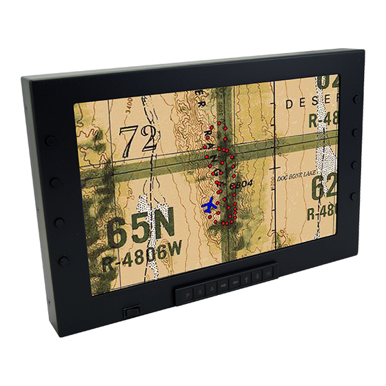
Front View Additional Information The FD141CV-C-6 utilizes a state of the art digital video decoding chipset for video input. The available video sources are HDSDI (High Definition SDI), VGA (Computer Video, such as a Moving Map) and Composite Video (Camera, Standard Definition DVD). -
Page 4: Specifications
Solar Radiation – MIL-STD-810F (N3) Method 505.4, Procedure I, Cycle A1 Installation Instructions All cabin equipment, such as the FD141CV-C-6, should be installed on a non-essential bus and have a dedicated circuit breaker. TECHNICAL SUPPORT © 2017 FDS Avionics Corp. -
Page 5: Power
Deerfield Laboratory, Inc. Part No. 162-1 (www.deerfieldlab.com, (650) 632-4090). In most cases this should be added to the video output of the source. TECHNICAL SUPPORT © 2017 FDS Avionics Corp. All Rights Reserved. 470-239-7421 or FDSAvionics.com... -
Page 6: Power And Ground Wiring
Also, use short heavy gauge wire and a clean tight connection for ground. It is the installer's responsibility to understand the product's requirements in order to install the product in compliance with industry standards and safety. TECHNICAL SUPPORT © 2017 FDS Avionics Corp. All Rights Reserved. 470-239-7421 or FDSAvionics.com... -
Page 7: Power/Video Pin Out
USB + 5VDC (Red) USB Ground (Black) Vertical Sync (Pin 14 on Standard VGA) Red Ground (Pin 6 on Standard VGA) Green Ground (Pin 7 on Standard VGA) TECHNICAL SUPPORT © 2017 FDS Avionics Corp. All Rights Reserved. 470-239-7421 or FDSAvionics.com... -
Page 8: Hdsdi Pin Out
Revision Date: Rev: Document Number: 04/27/2017 MAN – FD141CV-C-6 Page 8 of 34 HDSDI (INPUT) CONNECTOR P/N: Amphenol 112235 Description Center Video Signal Shell Video Return TECHNICAL SUPPORT © 2017 FDS Avionics Corp. All Rights Reserved. 470-239-7421 or FDSAvionics.com... -
Page 9: Operation Instructions
When applying 28VDC power, the display will turn on and look for a valid input. If no input is found, the display will go to standby mode. The operator will be able to change the video output from the FD141CV-C-6 using the video source select switch on the LCD monitor. -
Page 10: Accessing The Menu Systems
Adjust to increase or decrease the level of color in the picture. Sharpness Adjust to sharpen or soften the picture. TECHNICAL SUPPORT © 2017 FDS Avionics Corp. All Rights Reserved. 470-239-7421 or FDSAvionics.com... - Page 11 Aspect Mode The ratio between the width and height of an image. Full Screen Allows full screen image on the monitor regardless of Scan or Over Scan mode. TECHNICAL SUPPORT © 2017 FDS Avionics Corp. All Rights Reserved. 470-239-7421 or FDSAvionics.com...
- Page 12 After you zoom in, the Horizontal and Vertical controls are active. Use the buttons to move horizontally and vertically within the zoomed area. TECHNICAL SUPPORT © 2017 FDS Avionics Corp. All Rights Reserved. 470-239-7421 or FDSAvionics.com...
- Page 13 Click on the arrow buttons to change the image of the screen Image Position displayed in the main area. These image indicators represent each computer connected to make up the Quad. TECHNICAL SUPPORT © 2017 FDS Avionics Corp. All Rights Reserved. 470-239-7421 or FDSAvionics.com...
- Page 14 Select to give the white color’s a reddish tint. 6500K Select to give the white color’s a neutral tint. 7500K Select to give the white color’s a bluish tint. 9300K User User manually adjusts color. TECHNICAL SUPPORT © 2017 FDS Avionics Corp. All Rights Reserved. 470-239-7421 or FDSAvionics.com...
- Page 15 Revision Date: Rev: Document Number: 04/27/2017 MAN – FD141CV-C-6 Page 15 of 34 Press the buttons to change the color saturation TECHNICAL SUPPORT © 2017 FDS Avionics Corp. All Rights Reserved. 470-239-7421 or FDSAvionics.com...
- Page 16 Revision Date: Rev: Document Number: 04/27/2017 MAN – FD141CV-C-6 Page 16 of 34 PIP (Picture in Picture) Menu TECHNICAL SUPPORT © 2017 FDS Avionics Corp. All Rights Reserved. 470-239-7421 or FDSAvionics.com...
- Page 17 Quad connections chosen for PIP (ie, Analog, HDMI). The PIP position may also move to any corner and/or side by side within the screen. TECHNICAL SUPPORT © 2017 FDS Avionics Corp. All Rights Reserved. 470-239-7421 or FDSAvionics.com...
- Page 18 Side by Side allows the user to view two screens at one time in an equal amount of space. TECHNICAL SUPPORT © 2017 FDS Avionics Corp. All Rights Reserved. 470-239-7421 or FDSAvionics.com...
- Page 19 Use the Multi Vision screen to manage your Quad Views. Multi Vision can Vision be turned on or off here by changing the option from off to on. TECHNICAL SUPPORT © 2017 FDS Avionics Corp. All Rights Reserved. 470-239-7421 or FDSAvionics.com...
- Page 20 Page 20 of 34 Image Control is maintained on this screen for each individual picture. Select Column or individual quad area to manage the size of images. TECHNICAL SUPPORT © 2017 FDS Avionics Corp. All Rights Reserved. 470-239-7421 or FDSAvionics.com...
- Page 21 Uses just the first physical MADI port for MADI input. Factory Reset Full restore back to the original factory settings. Backlight Sets the PWM level of the panel backlight. TECHNICAL SUPPORT © 2017 FDS Avionics Corp. All Rights Reserved. 470-239-7421 or FDSAvionics.com...
- Page 22 Allows the user to move the horizontal position of the OSD Menu. OSD V POS Allows the user to move the vertical position of the OSD Menu. OSD Blending Allows the user to adjust the OSD Transparency. TECHNICAL SUPPORT © 2017 FDS Avionics Corp. All Rights Reserved. 470-239-7421 or FDSAvionics.com...
- Page 23 Primarily a systems administrators function. Ability to notify all ids connected of potential issues. Set ID Enables administrator to set user preferences. Baud Rate A data transmission rate (bits/second). TECHNICAL SUPPORT © 2017 FDS Avionics Corp. All Rights Reserved. 470-239-7421 or FDSAvionics.com...
-
Page 24: Technical Drawing Monitor Only
Revision Date: Rev: Document Number: 04/27/2017 MAN – FD141CV-C-6 Page 24 of 34 Technical Drawing for FD141CV-C-6 TECHNICAL SUPPORT © 2017 FDS Avionics Corp. All Rights Reserved. 470-239-7421 or FDSAvionics.com... -
Page 25: Technical Drawing - Co-Pilot Position
Revision Date: Rev: Document Number: 04/27/2017 MAN – FD141CV-C-6 Page 25 of 34 Technical Drawing – Co-Pilot position with the FD141CV-C-6 TECHNICAL SUPPORT © 2017 FDS Avionics Corp. All Rights Reserved. 470-239-7421 or FDSAvionics.com... -
Page 26: Technical Drawing - Pilot Position
Revision Date: Rev: Document Number: 04/27/2017 MAN – FD141CV-C-6 Page 26 of 34 Technical Drawing – Pilot position with the FD141CV-C-6 TECHNICAL SUPPORT © 2017 FDS Avionics Corp. All Rights Reserved. 470-239-7421 or FDSAvionics.com... -
Page 27: Portrait Co-Pilot
Revision Date: Rev: Document Number: 04/27/2017 MAN – FD141CV-C-6 Page 27 of 34 Co-Pilot position with the FD141CV-C-6 The view demonstrated here is the FDARM-ML- LG in Co-Pilot mode. The monitor attached is an FD141CV-C-6. Multiple monitors sold at FDS Avionics Corp. are designed to fit on this arm. -
Page 28: Portrait Pilot
Revision Date: Rev: Document Number: 04/27/2017 MAN – FD141CV-C-6 Page 28 of 34 Pilot position with the FD141CV-C-6 The view demonstrated here is the FDARM-ML- LG (Ruggedized Arm) in Pilot mode. The monitor attached is an FD141CV-C-6. Multiple monitors sold at FDS Avionics Corp. -
Page 29: User Instructions For Attaching Arm Support
Page 29 of 34 User Instructions for Attaching the Arm Support Displaying the FD141CV-C-6 is easily accomplished with the support of FDS Avionics Corp. 10” Articulating Arm Support. Following these simply steps will allow the user to attach their monitor to the arm support in minutes. - Page 30 Finally, using the ratchet handle, replace the arm back onto the neck attached to the monitor. TECHNICAL SUPPORT © 2017 FDS Avionics Corp. All Rights Reserved. 470-239-7421 or FDSAvionics.com...
-
Page 31: Maintenance And Inspections
Inspect attachment points of swing arm to aircraft for loose or broken screws. Power on monitor and check to ensure video display operates properly with aircraft supplied video or check with display and menu functions. TECHNICAL SUPPORT © 2017 FDS Avionics Corp. All Rights Reserved. 470-239-7421 or FDSAvionics.com... -
Page 32: Technical Support
04/27/2017 MAN – FD141CV-C-6 Page 32 of 34 Technical Support Should you have any questions concerning this product or other FDS Avionics Corp. products, please contact our Product Support representatives at (470) 239-7421. FDS Avionics Corp. 6435 Shiloh Road Alpharetta, GA 30005... -
Page 33: Warranty
This warranty is not transferable. Any implied warranties expire at the express limited warranty expiration date. FDS shall not be held liable for any indirect, special, punitive, incidental or consequential damages. Some states do not allow limitation on the length of an implied warranty. In such states, the exclusions or limitations of this limited warranty may not apply. -
Page 34: Log Of Revisions
Document Number: 04/27/2017 MAN – FD141CV-C-6 Page 34 of 34 Log of Revisions Date Page Description 03/26/2013 Initial Release Company name change, Warranty, Wire Diagram, and 4/27/2017 formatting. TECHNICAL SUPPORT © 2017 FDS Avionics Corp. All Rights Reserved. 470-239-7421 or FDSAvionics.com...
Need help?
Do you have a question about the FD141CV-C-6 and is the answer not in the manual?
Questions and answers