Table of Contents
Advertisement
Quick Links
Advertisement
Table of Contents

Related Manuals for Lilin PIH-8176/8178


Summary of Contents for Lilin PIH-8176/8178
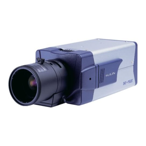
- Page 1 WIDE DYNAMIC RANGE DAY&NIGHT CAMERA PIH-8176/8178 INSTRUCTION MANUAL...
-
Page 2: Important Safeguards
IMPORTANT SAFEGUARDS CAUTION RISK OF ELECTRIC SHOCK DO NOT OPEN CAUTION TO REDUCE THE RISK OF ELECTRIC SHOCK, DO NOT REMOVE COVER (OR BACK) NO USER SERVICEABLE PARTS INSIDE. REFER SERVICING TO QUALIFIED SERVICE PERSONNEL. GRAPHIC SYMBOL EXPLANATION The lightning flash with arrowhead symbol, within an equilateral triangle, is intended to alert the user to the presence of uninsulated "dangerous voltage"... - Page 3 CAUTION Do not drop or strike this equipment. Sensitive electronics inside are vulnerable to excessive shock. Do not install the equipment near any naked flames or heat sources. Excessive heat could damage this unit. Do not expose this unit to rain or excessive moisture, avoid smoke and dust.
- Page 4 CONGRATULATIONS Thank you for purchasing this WDR Day/Night Camera. You now own one of the many fine CCTV products we manufactured. This product has been carefully inspected under rigid quality control and should reach you in perfect condition. With reasonable care, it will provide years of reliable performance.
-
Page 5: Table Of Contents
WARRANTY INFORMATION Please complete the following product purchase information. The factory will requests this information when contacted for technical support, or warranty repair. It is also valuable in case of loss or theft. Purchase Date Serial Number Model Number TABLE OF CONTENTS FEATURES PART DESCRIPTION CONFIGURATION OF THE MENU... -
Page 6: Features
FEATURES The PIH-8176/8178 series Wide Dynamic Range Day&Night Camera introduces supremacy in video quality. This compact yet full functional color DSP camera use SONY high sensitive 1/3" Vertical Double-Density interline transfer CCD. It delivers high resolution superior color images in day condition, and clear sharp monochrome pictures in night condition. - Page 7 DAY & NIGHT EXTERNAL CONTROL TRIGGER It is the function that can be switched to DAY mode or NIGHT mode by receiving DAY/NIGHT ON/OFF signal from external infrared illuminator. BACK LIGHT COMPENSATION Lights from the behind of the objects can be enhanced automatically to compensate for poorly illuminated scenes through DSP control such as iris and shutter speeds.
-
Page 8: Part Description
PART DESCRIPTION I G H T D A Y N DAY NIGHT... - Page 9 POWER AUDIO VIDEO D/N EXT. IN AC24V / DC 12V PIH-8176 POWER AUDIO VIDEO D/N EXT. IN Ac90 ~ 260V PIH-8178...
- Page 10 LENS MOUNT CAP Prevent Damages to the image sensor and to keep dust away. FOCAL LENGTH ADJUSTMENT RING AND LOCKING SCREW Use this ring to adjusts the back-focal distance or picture focus. Rotate this ring clockwise or counterclockwise for a CS-mount lens. Use the locking screw to lock the focal length.
- Page 11 AUTO IRIS CONNECTOR (4PIN SOCKET) Supplies power and control signals to an auto iris lens(jack not supplied). POWER LED Power ON/OFF indicator. AUDIO OUTPUT RCA CONNECTOR Audio signal output. VIDEO OUTPUT CONNECTOR Composite video signal output. AC24V/DC12V COMPATIBLE INPUT TERMINAL AC24V(AC24V 10%) or DC12V(DC12V 10%, Non-Polarity) power input.
-
Page 12: Configuration Of The Menu
CONFIGURATION OF THE MENU SETUP MENU 1/2 EXPOSE MODE AUTO SHUT SPD MIN SHUT SPD MAX AGCSLOW LOW Lux MODE SLOW BACK LIGHT FIX WGT. AUTO WGT. MANUAL SHUTTER SPD AGCSLOW LOW Lux MODE SLOW BACK LIGHT FIX WGT. AUTO WGT. AGCSLOW LOW Lux MODE WHITE BALANCE... - Page 13 IN LUX LEVEL SETUP MENU 2/2 IR CUT REMOVE AUTO OUT LUX LEVEL DELAY TIME DAY NIGHT TIME SCHE.. NIGHT DAY TIME EXTC.. INPUT POTENTIAL PEDESTAL APERTURE GAMMA IMAGE MIRROR FLIP Y NEGATIVE EPAN SPD EZOOM SPD ELECTRONIC P/Z EPAN OPERATION EZOOM OPERATION H OPSITION V POSITION...
-
Page 14: Setting Menu And Functions
SETTING MENU AND FUNCTIONS 1. Press [SET] key to enter SETUP MENU. 2. Press [UP/DOWN] key to select desired item. 3. Press [LEFT/RIGHT] key to select or adjust the parameters. 4. Press [SET] key to enter the SUB-MENU of selected item. 5. - Page 15 AUTO (Auto Expose) Switches automatically between electronic shutter speed and the low- brightness zone control selected in LOW Lux MODE to control the exposure time. MANUAL (Manual Expose) Electronic shutter speed is set up manually. The set value is fixed and it does not depend on luminance.
- Page 16 Low Lux Mode Setting AUTO EXPOSE The purpose of Low Lux Mode parameters SHUT SPD MIN 1/60 is to improve low-brightness zones that SHUT SPD MAX 1/500 LOW Lux MODE <AGC> make control of the electronic shutter and BACK LIGHT mechanical iris difficult.
- Page 17 B. SLOW Low-speed shutter control is activated when UMS zones are reached. As for the accumulated time when slow control is initiated, the staring shutter speed is as set in SHUT SPD MIN in the electronic shutter control mode (EXPOSE MODE=AUTO, WDR) or as selected in SHUTTER SPD when electronic shutter control is manual (EXPOSE MODE=MANUAL).
- Page 18 Control Range EXPOSE MODE Luminance UMS mode Control Range WD Control AUTO UMS mode Control Range E-Iris Control Luminance WD control High SHUT Speed Min High SHUT Speed Max AUTO E-Iris control Control parameters and EXPOSE control range Luminance AGCMin Gain UMS OFF No Control LOW SHUT MAX...
- Page 19 Back Light Compensation Setting AUTO EXPOSE Position the cursor beside BACK LIGHT SHUT SPD MIN 1/60 and select desired item. SHUT SPD MAX 1/100000 LOW Lux MODE <AGC> Back Light Compensation Mode BACK LIGHT changes as follows: FIX WGT. AUTO WGT. NOTES 1.
- Page 20 B. Shutter Speed Mode changes as follows MANUAL EXPOSE (Low Lux Mode=AGCSLOW or SLOW): SHUTTER SPD 1/60 LOW Lux MODE <AGC> 1/60(1/50) 1/100(1/120) 1/250 BACK LIGHT 1/2000 1/1000 1/500 Sec. 4. Position the cursor beside RET and press [SET] key and return to SETUP MENU 1/2. NOTES 1.
-
Page 21: White Balance
WHITE BALANCE Position the cursor beside WHITE BALANCE and select desired item by using [LEFT/RIGHT] key. White Balance Mode changes as follows: PUSH OUTDOOR INDOOR ATW (Auto-Tracing White Balance) Position the cursor beside WHITE BALANCE and select ATW by using [LEFT/RIGHT] key. -
Page 22: Flickerless
INDOOR Position the cursor beside WHITE BALANCE and select INDOOR by using [LEFT/RIGHT] key. The color temperature is fixed at 3200K for Indoor mode. FLICKERLESS Position the cursor beside FLICKERLESS and select OFF/ON by using [LEFT/RIGHT] key. Used only when the power source frequency is different from camera signal system. -
Page 23: Auto Iris Lens
NOTES 1. NTSC LL PHASE adjustment range 00~524(Each step is about 0.69 and the range is from 0 to 360 ). 2. PAL LL PHASE adjustment range 00~624(Each step is about 0.58 and the range is from 0 to 360 ). 4. -
Page 24: Privacy Mask
PRIVACY MASK Position the cursor beside PRIVACY MASK and select OFF by using [LEFT/RIGHT] key. 1. Position the cursor beside PRIVACY MASK PRIVACY ZONE MASK and select ON by using [LEFT/RIGHT] key. ZONE NUMBER EDIT POSITION <SET> 2. Press [SET] key to display the PRIVACY CLEAR ZONE <SET>... -
Page 25: Ir Cut Remove
IR CUT REMOVE Position the cursor beside IR CUT REMOVE and select desired item. IR Cut Remove Mode changes as follows: AUTO SCHEDULE EXTCTRL AUTO 1. Position the cursor beside IR CUT REMOVE and select AUTO by using [LEFT/RIGHT] key. 2. - Page 26 2. If Low Lux Mode set as "AGCSLOW", "SLOW" or "OFF", the setting options of IR CUT REMOVE are "IN", "OUT", "SCHEDULE" or "EXTCTRL" but "AUTO" function of IR CUT REMOVE is invalid. 3. If EXPOSE MODE set as "MANUAL" and Manual Shutter Speed set as 1/500, 1/10,000 ..
-
Page 27: Image
EXTCTRL 1. Position the cursor beside IR CUT REMOVE ICR EXTERNAL CTRL and select EXTC.. by using [LEFT/RIGHT] INPUT POTENTIAL key. 2. Press [SET] key to display the ICR EXTERNAL CTRL menu. 3. Position the cursor beside INPUT POTENTIAL and select LOW or HIGH by using [LEFT/RIGHT] key. - Page 28 MIRROR Position the cursor beside MIRROR and select OFF/ON by using [LEFT/ RIGHT] key. This mode reverses the left and right sides of the linear. MIRROR = OFF MIRROR = ON (Normal) (Right and left reversal) FLIP Position the cursor beside FLIP and select OFF/ON by using [LEFT/ RIGHT] key.
-
Page 29: Electronic P/Z
ELECTRONIC P/Z Position the cursor beside ELECTRONIC P/Z and press [SET] key to display ELECTRONIC P/Z menu. EPAN SPD Position the cursor beside EPAN SPD, ELECTRONIC P/Z adjust the Electronic Pan Speed by using EPAN SPD EZOOM SPD [LEFT/RIGHT] key. EPAN OPERATION EZOOM OPERATION EPAN SPD: 05~10. - Page 30 D. Position the cursor beside RET and press [SET] key to display screen, adjust the Electronic Zoom Magnification by using [LEFT/RIGHT] key. Magnification value of EZOOM will show up on the bottom-right of monitor. EZOOM Magnification: 01.00X ~ 02.56X. ELECTRONIC P/Z EPAN SPD EZOOM SPD EPAN OPERATION...
-
Page 31: Title Display
TITLE DISPLAY Position the cursor beside TITLE DISPLAY and press [SET] key to display TITLE SETUP menu. H POSITION Position the cursor beside H POSITION TITLE SETUP and select Horizontal Position of the title H POSITION V POSITION by using [LEFT/RIGHT] key. DATE 2006/01/01 TIME... - Page 32 CAMERA ID 1. Position the cursor beside CAMERA ID and select OFF/ON by using [LEFT/RIGHT] key. OFF: CAMERA ID SETUP is not displayed. ON : CAMERA ID SETUP is displayed on the screen. 2. Press [SET] key to display the CAMERA ID SETUP menu. CAMERA ID SETUP Character Cursor...
-
Page 33: Factory Default
C. Position the cursor beside desired character, and using [LEFT/RIGHT] key to confirm. D. Press [SET] key to change the character. 6. To Delete Camera ID Move the cursor to RESET and press [SET] key to delete. NOTE If any of these 3 functions, "DATE DISPLAY", "TIME DISPLAY" or "CAMERA ID", has been turned "ON", magnification value of EZOOM will show below the Date, Time &... - Page 34 CHANGING THE PLUG ON AN AUTO IRIS LENS CABLE The camera is supplied with a plug to fit the AUTO IRIS connector. To connect an auto iris lens, first replace the plug on the lens cable with the supplied plug. Solder the lens cable to the pins of the supplied plug (For cable pin assignment, refer to the instruction manual for the lens.).
- Page 35 FITTING THE LENS Remove the lens mount cap. Screw in the C mount ring(not supplied), unit it is secured. When using a CS mount lens skip step2. Screw in the lens, unit it is secured. Insert the lens plug in the AUTO IRIS connector, when fitting a manual- iris lens, skip step4.
- Page 36 FITTING THE CAMERA 1. The mounting base can be attached to either the top or bottom of the camera. 2. Tighten the screw to attach the mounting base. Please refer to the following drawing. IG H T D A Y N IG H T D A Y N CONNECTION OF POWER SUPPLY CABLE (AC24V or DC12V)
-
Page 37: Specifications
SPECIFICATIONS Wide Dynamic Range Day&Night Camera Model No. PIH-8176N PIH-8178N PIH-8176P PIH-8178P DC12V 10% DC12V 10% Power Input Voltage AC90 ~ 260V AC90 ~ 260V AC24V 10% AC24V 10% Pick Up Element 1/3" Vertical Double-Density Interline CCD Sensor Effective Pixels 768(H) x 494(V) 752(H) x 582(V) Chip Size... - Page 38 MERIT LILIN ENT. CO., LTD http://www.meritlilin.com 66-817CSE...
Need help?
Do you have a question about the PIH-8176/8178 and is the answer not in the manual?
Questions and answers