Table of Contents
Advertisement
Quick Links
Проконсультироваться и купить данное оборудование вы можете в компании «АНД-Системс»
адрес: 125480, г.Москва, ул.Туристская, д.33/1; site: https://andpro.ru тел: +7 (495) 545-4870 email: info@andpro.ru
При обращении используйте промокод AND-PDF и получите скидку.
S
S
UPER
ERVER
®
4028GR-TR
4028GR-TRT
4028GR-TR2
4028GR-TRT2
USER'S MANUAL
Revision 1.0c
Advertisement
Table of Contents

Related Manuals for Supermicro SUPERSERVER 4028GR-TR


Summary of Contents for Supermicro SUPERSERVER 4028GR-TR
- Page 1 Проконсультироваться и купить данное оборудование вы можете в компании «АНД-Системс» адрес: 125480, г.Москва, ул.Туристская, д.33/1; site: https://andpro.ru тел: +7 (495) 545-4870 email: info@andpro.ru При обращении используйте промокод AND-PDF и получите скидку. UPER ERVER ® 4028GR-TR 4028GR-TRT 4028GR-TR2 4028GR-TRT2 USER’S MANUAL Revision 1.0c...
- Page 2 This product, including software and documentation, is the property of Supermicro and/or its licensors, and is supplied only under a license. Any use or reproduction of this product is not allowed, except as expressly permitted by the terms of said license.
-
Page 3: About This Manual
About this Manual This manual is written for professional system integrators and PC technicians. It provides information for the installation and use of the SuperServer 4028GR-TR(T)(2). Installation and maintenance should be performed by experienced technicians only. Please refer to the server specifications page on our Web site for updates on supported memory, processors and operating systems (http://www.supermicro. -
Page 4: Table Of Contents
SATA Subsystem ..................... 1-5 Front Control Panel ..................1-5 Cooling System ....................1-5 GPU Subsystem ....................1-5 Contacting Supermicro ..................1-7 Chapter 2 Rack Installation Unpacking the System ..................2-1 Preparing for Setup ..................2-1 Choosing a Setup Location ................2-1 Warnings and Precautions ................ - Page 5 Preface Chapter 3 System Interface Overview ......................3-1 Control Panel Buttons ..................3-2 Power ......................3-2 Reset ....................... 3-2 Control Panel LEDs ..................3-2 Power ......................3-2 HDD ......................... 3-2 NIC2 ........................ 3-3 NIC1 ........................ 3-3 Information LED ....................3-3 Power Fail .......................
- Page 6 UPER ERVER 4028GR-TR(T)(2) Manual Connecting Cables ..................5-2 Connecting Data Cables ................. 5-2 Connecting Power Cables ................5-2 Connecting the Control Panel ................. 5-2 Input/Output Ports ................... 5-3 Installing the Processor and Heatsink ............5-4 Installing an LGA 2011 Processor ..............5-4 Installing a CPU Heatsink ................
- Page 7 Chapter 7 BIOS Introduction ...................... 7-1 Starting BIOS Setup Utility ................7-1 How To Change the Configuration Data ............7-1 Starting the Setup Utility ................. 7-2 Main Setup ...................... 7-2 Advanced Setup Configurations..............7-4 Event Logs ....................7-37 IPMI ....................... 7-39 Security Settings ...................
- Page 8 Notes viii...
-
Page 9: Chapter 1 Introduction
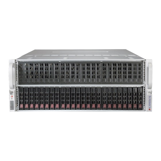
Chapter 1 Introduction Overview The SuperServer 4028GR-TR(T)(2) is a GPU/Xeon Phi optimized server comprised of two main subsystems: the SC418GTS-R3200B/R4000B 4U server chassis and the X10DRG-O(T)+ motherboard, augmented by a daughter board for PCIe expansion capabilities. The models and features are:... -
Page 10: Motherboard Features
SUPERSERVER 4028GR-TR(T)(2) User's Manual Motherboard Features At the heart of the server is the X10DRG-O(T)+-CPU, a dual processor motherboard based on the Intel PCH C612 chipset. Below are the main features. (See Figure 1-1 for a block diagram) Processors The X10DRG-O(T)+-CPU supports dual Intel E5-2600 v3/v4 series processors in LGA 2011 sockets (Socket R3). - Page 11 Chapter 1: Introduction #H-3 #H-2 #H-1 #D-3 #G-3 #D-2 #G-2 #D-1 #G-1 #C-3 #F-3 #C-2 #F-2 VR12.5 VR12.5 #C-1 #F-1 5 PHASE 5 PHASE #B-3 #E-3 160W 160W #B-2 #E-2 #B-1 CPU1 CPU2 #E-1 #A-3 #A-2 9.6G #A-1 DDR4 DDR4 9.6G #3 #1 DMI2...
-
Page 12: Input/Output Ports
Intelligent Platform Management Interface (IPMI) 2.0 is a hardware-level interface specification that provides remote access, monitoring and administration for Supermicro servers. IPMI enables administrators to view a server hardware status remotely, receive an alarm automatically if a failure occurs, and power cycle a system that is non-responsive. -
Page 13: Gpu Subsystem
Chapter 1: Introduction GPU Subsystem The 4028GR-TR(T)(2) server represents one of Supermicro's massively parallel processing multiple GPU/Xeon Phi servers, with support for up to eight GPUs/ Xeon Phis. NVIDIA Tesla GPUs place this system at the forefront of today's GPU computing solutions. -
Page 14: Contacting Supermicro
SUPERSERVER 4028GR-TR(T)(2) User's Manual Contacting Supermicro Headquarters Address: Super Micro Computer, Inc. 980 Rock Ave. San Jose, CA 95131 U.S.A. Tel: +1 (408) 503-8000 Fax: +1 (408) 503-8008 Email: marketing@supermicro.com (General Information) support@supermicro.com (Technical Support) Web Site: www.supermicro.com Europe Address: Super Micro Computer B.V. -
Page 15: Chapter 2 Rack Installation
Chapter 2: Rack Intallation Chapter 2 Rack Installation This chapter provides instructions for preparing and mounting your chassis in a rack. Unpacking the System You should inspect the box the chassis was shipped in and note if it was damaged in any way. -
Page 16: Warnings And Precautions
SuperServer 4028GR-TR(T)(2) User's Manual Warnings and Precautions Rack Precautions • Ensure that the leveling jacks on the bottom of the rack are fully extended to the floor with the full weight of the rack resting on them. • In single rack installations, stabilizers should be attached to the rack. -
Page 17: Rack Mounting Considerations
Chapter 2: Rack Intallation Rack Mounting Considerations Ambient Operating Temperature If installed in a closed or multi-unit rack assembly, the ambient operating temperature of the rack environment may be greater than the ambient temperature of the room. Therefore, consideration should be given to installing the equipment in an environment compatible with the manufacturer’s maximum rated ambient temperature (TMRA). -
Page 18: Procedure For Rack Mounting
SuperServer 4028GR-TR(T)(2) User's Manual Procedure for Rack Mounting This section provides information on installing a 4U chassis into a rack unit with the rails provided. There are a variety of rack units on the market, so the assembly procedure may differ slightly. Also refer to the installation instructions for your rack unit. -
Page 19: Installing The Inner Rails On The Chassis
Chapter 2: Rack Intallation Figure 2-2. Installing the Inner Rails Installing the Inner Rails on the Chassis Installing the Inner Rails 1. Identify the left and right side inner rails. Place the correct inner rail on the side of the chassis, aligning the hooks of the chassis with the inner rail holes. Make sure the rail faces "outward"... -
Page 20: Installing The Outer Rails Onto The Rack
SuperServer 4028GR-TR(T)(2) User's Manual Installing the Outer Rails onto the Rack Installing the Outer Rails 1. Press upward on the locking tab at the rear end of the middle rail. 2. Push the middle rail back into the outer rail. -
Page 21: Installing The Chassis Into A Rack
Chapter 2: Rack Intallation Figure 2-4. Installing the Chassis into a Rack Note: Figures are for illustrative purposes only. Always install servers into racks in the lower positions first. Installing the Chassis into a Rack Installing the Chassis into a Rack: 1. -
Page 22: Removing The Chassis From The Rack
SuperServer 4028GR-TR(T)(2) User's Manual Removing the Chassis from the Rack Caution! It is dangerous for a single person to off-load the heavy chassis from the rack without assistance. Be sure to have sufficient assistance supporting the chassis when removing it from the rack. Use a lift. -
Page 23: Chapter 3 System Interface
Chapter 3: System Interface Chapter 3 System Interface Overview The server includes a control panel on the front that houses power buttons and status monitoring lights. The externally accessible hard drives display status lights. The power supply displays status lights visible from the back of the chassis. Figure 3-1. -
Page 24: Control Panel Buttons
SuperServer 4028GR-TR(T)(2) User's Manual Control Panel Buttons The chassis includes two push-buttons that control power to the system. Power The main power switch applies or removes primary power from the power supply to the server but maintains standby power. To perform most maintenance tasks, unplug the system to remove all power. -
Page 25: Nic2
Chapter 3: System Interface NIC2 Indicates network activity on GLAN2 when flashing. NIC1 Indicates network activity on GLAN1 when flashing. Information LED Alerts operator to several states, as noted in the table below. Information LED Status Description An overheat condition has occured. Continuously on and red (This may be caused by cable congestion.) Blinking red (1Hz) -
Page 26: Overheating
Some backplanes allow the overheat temperature to be set at 45, 50, or 55 by changing a jumper setting. For more information, consult the backplane user manual at www.supermicro.com. (Click Support, then the Manuals link.) Responses If the server overheats: 1. -
Page 27: Power Supply Leds
Chapter 3: System Interface Power Supply LEDs On the rear of the power supply module, an LED displays the status. • Solid Green: When illuminated, indicates that the power supply is on. • Solid Amber: When illuminated, indicates the power supply is plugged in and turned off, or the system is off but in an abnormal state. - Page 28 SuperServer 4028GR-TR(T)(2) User's Manual Notes...
-
Page 29: Chapter 4 Standardized Warning Statements For Ac Systems
Only certified technicians should attempt to install or configure components. Read this chapter in its entirety before installing or configuring components in the Supermicro chassis. Some warnings may not apply for your system. These warnings may also be found on our web site at www.supermicro.com/about/ policies/safety_information.cfm. - Page 30 SUPERSERVER 4028GR-TR(T)(2) User's Manual Warnung WICHTIGE SICHERHEITSHINWEISE Dieses Warnsymbol bedeutet Gefahr. Sie befinden sich in einer Situation, die zu Verletzungen führen kann. Machen Sie sich vor der Arbeit mit Geräten mit den Gefahren elektrischer Schaltungen und den üblichen Verfahren zur Vorbeugung vor Unfällen vertraut.
- Page 31 Chapter 4: Warning Statements for AC Systems جسذٌة اصابة ًتتسبب ف حالة ٌوكي أى ًاًك ف خطز ًٌٌع هذا الزهز !تحذٌز الذوائز بالوخاطز الٌاجوة عي ي على علن ، ك هعذات تعول على أي قبل أى الكهزبائٍة حىادث أي وقىع وٌع...
-
Page 32: Installation Instructions
SUPERSERVER 4028GR-TR(T)(2) User's Manual Installation Instructions Warning! Read the installation instructions before connecting the system to the power source. 設置手順書 システムを電源に接続する前に、 設置手順書をお読み下さい。 警告 将此系统连接电源前,请先阅读安装说明。 警告 將系統與電源連接前,請先閱讀安裝說明。 Warnung Vor dem Anschließen des Systems an die Stromquelle die Installationsanweisungen lesen. ¡Advertencia! Lea las instrucciones de instalación antes de conectar el sistema a la red de alimentación. -
Page 33: Circuit Breaker
Chapter 4: Warning Statements for AC Systems Circuit Breaker Warning! This product relies on the building's installation for short-circuit (overcurrent) protection. Ensure that the protective device is rated not greater than: 250 V, 20 A. サーキッ ト ・ ブレーカー この製品は、 短絡 (過電流) 保護装置がある建物での設置を前提としています。 保護装置の定格が250 V、... -
Page 34: Power Disconnection Warning
SUPERSERVER 4028GR-TR(T)(2) User's Manual 경고! 이 제품은 전원의 단락(과전류)방지에 대해서 전적으로 건물의 관련 설비에 의존합니다. 보호장치의 정격이 반드시 250V(볼트), 20A(암페어)를 초과하지 않도록 해야 합니다. Waarschuwing Dit product is afhankelijk van de kortsluitbeveiliging (overspanning) van uw electrische installatie. Controleer of het beveiligde aparaat niet groter gedimensioneerd is dan 220V, 20A. - Page 35 Chapter 4: Warning Statements for AC Systems ¡Advertencia! El sistema debe ser disconnected de todas las fuentes de energía y del cable eléctrico quitado de los módulos de fuente de alimentación antes de tener acceso el interior del chasis para instalar o para quitar componentes de sistema. Attention Le système doit être débranché...
-
Page 36: Equipment Installation
SUPERSERVER 4028GR-TR(T)(2) User's Manual Equipment Installation Warning! Only trained and qualified personnel should be allowed to install, replace, or service this equipment. 機器の設置 トレーニングを受け認定された人だけがこの装置の設置、 交換、 またはサービスを許可 されています。 警告 只有经过培训且具有资格的人员才能进行此设备的安装、更换和维修。 警告 只有經過受訓且具資格人員才可安裝、更換與維修此設備。 Warnung Das Installieren, Ersetzen oder Bedienen dieser Ausrüstung sollte nur geschultem, qualifiziertem Personal gestattet werden. -
Page 37: Restricted Area
Chapter 4: Warning Statements for AC Systems Waarschuwing Deze apparatuur mag alleen worden geïnstalleerd, vervangen of hersteld door geschoold en gekwalificeerd personeel. Restricted Area Warning! This unit is intended for installation in restricted access areas. A restricted access area can be accessed only through the use of a special tool, lock and key, or other means of security. -
Page 38: Battery Handling
SUPERSERVER 4028GR-TR(T)(2) User's Manual אזור עם גישה מוגבלת !אזהרה יש להתקין את היחידה באזורים שיש בהם הגבלת גישה. הגישה ניתנת בעזרת .)'כלי אבטחה בלבד (מפתח, מנעול וכד محظورة مناطق ٍنتركُبها ف هذه انىحذة تخصيص تم ،أداة خاصت من خالل استخذاو... - Page 39 Chapter 4: Warning Statements for AC Systems Warnung Bei Einsetzen einer falschen Batterie besteht Explosionsgefahr. Ersetzen Sie die Batterie nur durch den gleichen oder vom Hersteller empfohlenen Batterietyp. Entsorgen Sie die benutzten Batterien nach den Anweisungen des Herstellers. Attention Danger d'explosion si la pile n'est pas remplacée correctement. Ne la remplacer que par une pile de type semblable ou équivalent, recommandée par le fabricant.
-
Page 40: Redundant Power Supplies (If Applicable To Your System)
SUPERSERVER 4028GR-TR(T)(2) User's Manual Redundant Power Supplies (if applicable to your system) Warning! This unit might have more than one power supply connection. All connections must be removed to de-energize the unit. 冗長電源装置 このユニッ トは複数の電源装置が接続されている場合があります。 ユニッ トの電源を切るためには、 すべての接続を取り外さなければなりません。 警告 此部件连接的电源可能不止一个,必须将所有电源断开才能停止给该部件供电。... -
Page 41: Backplane Voltage (If Applicable To Your System)
Chapter 4: Warning Statements for AC Systems امداد الطاقة بوحدات عدة اتصاالت جهاز ال يكون لهذا قد الكهرباء عن وحدة ال لعسل كافة االتصاالت يجب إزالة 경고! 이 장치에는 한 개 이상의 전원 공급 단자가 연결되어 있을 수 있습니다. 이 장치에... -
Page 42: Comply With Local And National Electrical Codes
SUPERSERVER 4028GR-TR(T)(2) User's Manual מתח בפנל האחורי !הרה אז קיימת סכנת מתח בפנל האחורי בזמן תפעול המערכת. יש להיזהר במהלך .העבודה اللىحة أوالطاقة المىجىدة على التيار الكهزبائي مه خطز هناك هذا الجهاس خدمة كه حذرا عند يعمل النظام عندما يكىن... -
Page 43: Product Disposal
Chapter 4: Warning Statements for AC Systems Attention L'équipement doit être installé conformément aux normes électriques nationales et locales. תיאום חוקי החשמל הארצי !אזהרה הציוד חייבת להיות תואמת לחוקי החשמל המקומיים והארציים התקנת المتعلقة المحلية والىطىية قىاويه يجب أن يمتثل لل الكهربائية... -
Page 44: Hot Swap Fan Warning (If Applicable To Your System)
SUPERSERVER 4028GR-TR(T)(2) User's Manual ¡Advertencia! Al deshacerse por completo de este producto debe seguir todas las leyes y reglamentos nacionales. Attention La mise au rebut ou le recyclage de ce produit sont généralement soumis à des lois et/ou directives de respect de l'environnement. Renseignez-vous auprès de l'organisme compétent. - Page 45 Chapter 4: Warning Statements for AC Systems 警告 危險的可移動性零件。請務必與轉動的風扇葉片保持距離。 當您從機架移除風扇裝 置,風扇可能仍在轉動。小心不要將手指、螺絲起子和其他物品太靠近風扇。 Warnung Gefährlich Bewegende Teile. Von den bewegenden Lüfterblätter fern halten. Die Lüfter drehen sich u. U. noch, wenn die Lüfterbaugruppe aus dem Chassis genommen wird. Halten Sie Finger, Schraubendreher und andere Gegenstände von den Öffnungen des Lüftergehäuses entfernt.
-
Page 46: Power Cable And Ac Adapter
Electrical Appliance and Material Safety Law prohibits the use of UL or CSA -certified cables (that have UL/CSA shown on the code) for any other electrical devices than products designated by Supermicro only. 電源コードとACアダプター 製品を設置する場合、 提供または指定された接続ケーブル、 電源コードとACアダプター... - Page 47 Appareils électroménagers et de loi sur la sécurité Matériel interdit l'utilisation de UL ou CSA câbles certifiés qui ont UL ou CSA indiqué sur le code pour tous les autres appareils électriques que les produits désignés par Supermicro seulement.
- Page 48 SUPERSERVER 4028GR-TR(T)(2) User's Manual Notes 4-20...
-
Page 49: Chapter 5 Advanced Motherboard Setup
Chapter 5: Advanced Serverboard Setup Chapter 5 Advanced Motherboard Setup This chapter covers connecting cables and describes jumpers. A layout and quick reference chart are included. The 4028GR-TR(2) uses the X10DRG-O+-CPU motherboard, and the 4028GR- TRT(2) uses the X10DRG-OT+-CPU motherboard. They use the X9DRG-O-PCIE or X10DRG-O-PCIE daughter board to facilitate PCI-E expansion cards. -
Page 50: Connecting Cables
SUPERSERVER 4028GR-TR(T)(2) User's Manual Connecting Cables Assuming the X10DRG-O(T)+ motherboard is installed, the next step is to connect the cables to the board. These include the data (ribbon) cables for the peripherals and control panel and the power cables. Connecting Data Cables... -
Page 51: Input/Output Ports
Chapter 5: Advanced Serverboard Setup Input/Output Ports Figure 5-1. I/O Ports IO Ports USB 3.0 Port 5 LAN Port 1 USB 3.0 Port 6 LAN Port 2 IPMI Dedicated LAN VGA Port USB 3.0 Port 7 UID Switch USB 3.0 Port 8 For X10DRG-O+ the LAN ports are 1Gb;... -
Page 52: Installing The Processor And Heatsink
• Install the processor into the CPU socket before installing the heatsink. • Refer to the Supermicro web site for updates on CPU support. Installing an LGA 2011 Processor Installing a CPU 1. There are two levers on the LGA 2011 socket. - Page 53 Chapter 5: Advanced Serverboard Setup 3. W ith the sec ond lever f ully Open the load plate. retracted, gently push down on the "Open 1st" lever to loosen the load plate. Lift the load plate with your fingers to open it completely. 4.
- Page 54 SUPERSERVER 4028GR-TR(T)(2) User's Manual Gently close the load plate. 7. With the "Close 1st" lever fully retracted, gently close the load plate. Push down and lock the lever labeled "Close 1st". 8. Make sure the locking mechanism on the "Close 1st" lever catches the lip of the load plate.
-
Page 55: Installing A Cpu Heatsink
Chapter 5: Advanced Serverboard Setup Installing a CPU Heatsink 1. Remove power from the system and unplug the AC power cord from the power supply. 2. Do not apply any thermal grease to the heatsink or the CPU die; the required amount has already been applied. -
Page 56: Installing Memory
2400/2133/1866/1600 MHz in 24 slots. Memory speed is dependent on the CPUs. For best memory performance, install memory modules of the same type and same speed. For the latest CPU/memory updates, refer to the Supermicro website. Caution: Exercise care installing or removing DIMM modules to avoid damage. -
Page 57: Processor/Dimm Population Configurations
Chapter 5: Advanced Serverboard Setup Processor/DIMM Population Configurations • For memory to work properly, follow the tables below for memory installation. • Install DIMMs in pairs, that is, use an even number of DIMMs. • All channels in a system will run at the fastest common frequency. Processors and their Corresponding Memory Modules CPU# Corresponding DIMM Modules... -
Page 58: Motherboard Details
SUPERSERVER 4028GR-TR(T)(2) User's Manual Motherboard Details USB7/8 USB5/6 (3.0) LAN2 LAN1 (3.0) CTRL X10DRG-O+-CPU Rev. 1.00 JPW22 JPW24 JPW21 JPW23 Battery JBT1 1G/10G MAC CODE BAR CODE BIOS IPMI CODE 10G SAN MAC LICENSE CPU2 CPU1 Figure 5-4. X10DRG-O(T)+ Layout Notes Jumpers not indicated are for test purposes only. - Page 59 Chapter 5: Advanced Serverboard Setup Jumpers Jumper Description Default Setting JBT1 Clear CMOS See Section 5-8 JPB1 BMC Enable Pins 1-2 (Enabled) JPG1 VGA Enable Pins 1-2 (Enabled) JPL1 GLAN1/GLAN2 Enable Pins 1-2 (Enabled) JPME2 Manufacturer (ME) Mode Select Pins 1-2 (Normal) JWD1 Watch-Dog Timer Enable Pins 1-2 (Reset)
-
Page 60: Pci-E Daughter Board
SUPERSERVER 4028GR-TR(T)(2) User's Manual LED Indicators Description State Status Rear UID LED Blue: On Unit Identified Onboard PWR LED System Power On LEDM1 BMC Heartbeat LED Green: Blinking BMC Normal Daughter Boards The system includes a daughter board for GPU/PCIe expansion capabilities. -
Page 61: Connector Definitions
Chapter 5: Advanced Serverboard Setup Lanes Lanes X10DRG-O-PCIE REV:1.00 Figure 5-6. X10DRG-O-PCIE Daughter Board (for 4028GR-TR[T]2) Connector Definitions Power Connectors The motherboard has four proprietary 12V 8-pin Power Connector main power connectors (JPW21- Pin Definitions JPW24). These must be connected to Pins Definition the power supply to provide adequate... -
Page 62: Control Panel Connectors
SUPERSERVER 4028GR-TR(T)(2) User's Manual Control Panel Connectors Ground x (Key) x (Key) Power On LED 3.3V HDD LED FP UID/3.3V Stby NIC1 LED (Link) NIC1 LED (Activity) NIC2 LED (Link) NIC2 LED (Activity) OH/Fan Fail/UID LED Blue LED (UID Cathode) PWR Fail LED 3.3V... - Page 63 Chapter 5: Advanced Serverboard Setup Power Fail LED PWR Fail LED Pin Definitions The Power Fail LED connection is located (JF1) on pins 5 and 6 of JF1. Refer to the table Pin# Definition on the right for pin definitions. 3.3V PWR Fail LED Overheat/Fan Fail/UID LED...
- Page 64 SUPERSERVER 4028GR-TR(T)(2) User's Manual HDD LED/ UID Button HDD/UID LED Pin Definitions The HDD LED connection is pin 14 of JF1. (JF1) It lights the LED upon HDD activity. Pin# Definition The pin 13 connection carries the signal UID Signal/3.3V from the UID button on the front panel.
-
Page 65: Rear Input/Output Connections
Chapter 5: Advanced Serverboard Setup Rear Input/Output Connections Universal Serial Bus (USB) Four USB 3.0 ports (USB 5, 6, 7, and 8) are accessable on the I/O panel at the rear of the chassis. In addition, two internal headers provide four USB 2.0 connections (USB 0/1, USB 2/3) for front panel support. -
Page 66: Internal Headers
SUPERSERVER 4028GR-TR(T)(2) User's Manual Internal Headers Fan Headers The motherboard has eight system/CPU Fan Header Pin Definitions fan headers (Fans 1~8). All are 4-pin fan headers, which are backward compatible Pin# Definition with traditional 3-pin fans. However, Ground fan speed control is available for 4-pin +12V fans only. - Page 67 Chapter 5: Advanced Serverboard Setup I-SGPIO1/2 & S-SGPIO Headers T-SGPIO Pin Definitions Three SGPIO (Serial-Link General Purpose Pin# Definition Definition Input/Output) headers are provided on the motherboard. I-SGPIO1 supports I-SATA Ground Data 0-3, I-SGPIO2 supports I-SATA 4/5. S-SGPIO is used for S-SATA 0-3. See the Load Ground table on the right for pin definitions.
-
Page 68: Jumper Settings
SUPERSERVER 4028GR-TR(T)(2) User's Manual Jumper Settings Explanation of Jumpers To modify the operation of the motherboard, jumpers can be used Connector to choose between optional settings. Pins Jumpers create shorts between two pins to change the function of the connector. Pin 1 is identified with... - Page 69 Chapter 5: Advanced Serverboard Setup VGA Enable/Disable VGA Enable/Disable Jumper Settings JPG1 allows you to enable or disable the Jumper Setting Definition VGA port. The default position is on pins 1 Pins 1-2 Enabled and 2 to enable VGA. Pins 2-3 Disabled Watch Dog Enable/Disable Watch Dog...
-
Page 70: Onboard Indicators
SUPERSERVER 4028GR-TR(T)(2) User's Manual Onboard Indicators LAN Port LEDs LAN 1/2 Link LED Activity LED The Ethernet ports have two LEDs. On each port, one LED indicates activity and the other indicates the link speed of the GLAN Activity connection. It may be green, amber or off. -
Page 71: 5-10 Sata Ports
There are six Serial ATA 3.0 ports (I-SATA0-I-SATA5), supported by the Intel PCH on the motherboard. There are also four S-SATA connectors (S-SATA0-3), supported by the Intel SCU. I-SATA4/5, colored in yellow, are used with Supermicro SuperDOM (Disk-on-Module) connectors with power pins built in, and are compatible with regular SATA HDDs and SATA DOMs that requires external power cables. -
Page 72: 5-11 Installing Software
SUPERSERVER 4028GR-TR(T)(2) User's Manual 5-11 Installing Software The Supermicro ftp site contains drivers and utilities for your system at ftp://ftp.supermicro.com. Some of these must be installed, such as the chipset driver. After accessing the ftp site, go into the CDR_Images directory and locate the ISO file for your motherboard. -
Page 73: Superdoctor ® 5
Chapter 5: Advanced Serverboard Setup SuperDoctor ® The Supermicro SuperDoctor 5 is a hardware and operating system services monitoring program that functions in a command-line or web-based interface in Windows and Linux operating systems. The program monitors system health information such as CPU temperature, system voltages, system power consumption, fan speed, and provides alerts via email or Simple Network Management Protocol (SNMP). -
Page 74: 5-12 Onboard Battery
Figure 5-10. SuperDoctor 5 Interface Display Screen (Remote Control) Note: The SuperDoctor 5 program and User’s Manual can be downloaded from the Supermicro web site at http://www.supermicro.com/products/nfo/sms_sd5.cfm. For Linux, we recommend that you use the SuperDoctor II application instead. 5-12 Onboard Battery Please handle used batteries carefully. -
Page 75: Chapter 6 Advanced Chassis Setup
Chapter 6: Advanced Chassis Setup Chapter 6 Advanced Chassis Setup This chapter covers the steps required to install components and perform maintenance on the SC418GTS-R3200BP chassis. The only tool required is a Phillips screwdriver. Your system may require the installation of processors, memory, drives or expansion cards. -
Page 76: Static-Sensitive Devices
SUPERSERVER 4028GR-TR(T)(2) USER'S MANUAL Static-Sensitive Devices Electrostatic discharge (ESD) can damage electronic com ponents. To prevent damage to any printed circuit boards (PCBs), it is important to handle them very carefully. The following measures are generally sufficient to protect your equipment from ESD damage. -
Page 77: Installing Hard Drives
2. Use the handle to pull the drive and its carrier out of the chassis. Figure 6-3. Removing a Hard Drive Carrier Enterprise level hard disk drives are recommended for use in Supermicro chassis and servers. For information on recommended HDDs, visit the Supermicro Web site... - Page 78 SUPERSERVER 4028GR-TR(T)(2) USER'S MANUAL Installing a Hard Drive into a Drive Carrier 1. Insert a drive into the carrier with the PCB side facing down and the connector end toward the rear of the carrier. 2. Align the drive in the carrier so that the screw holes of both line up. Note that there are holes in the carrier marked “SATA”...
-
Page 79: Removing The Chassis Cover
Chapter 6: Advanced Chassis Setup Removing the Chassis Cover You will need to access the inside of the system to complete certain procedures such as replacing fans. Removing the Chassis Cover If working with components such as memory, processors or heatsinks, start by shutting the system down and disconnecting the AC power cord. -
Page 80: Installing Expansion Cards
SUPERSERVER 4028GR-TR(T)(2) USER'S MANUAL Installing Expansion Cards The system includes a daughter board for GPU/PCIe expansion capabilities. See Chapter 1, "PCI Expansion Slots" or Chapter 5, "Daughter Boards" for more information. Installing Expansion Cards 1. Power down the system as described in Section 6-2, and open the chassis cover. -
Page 81: Installing The Air Shroud
Chapter 6: Advanced Chassis Setup Installing the Air Shroud Air shrouds concentrate airflow to maximize fan efficiency. Installing the PCI-E Air Shroud 1. Remove the GPU retention bracket screw (located on the right side) and remove the GPU retention bracket. 2. -
Page 82: Replacing Fans
SUPERSERVER 4028GR-TR(T)(2) USER'S MANUAL Replacing Fans The chassis contains eight 8-cm system fans that provide cooling for the system. All fans are hot-swappable, so there is no need to power down the system when switching fans. Changing a System Fan 1. -
Page 83: Power Supply
The failed power module can be replaced without powering-down the system. Replace with the same model. Replacement modules can be ordered directly from Supermicro. An amber light on the power supply is illuminated when the power is switched off. - Page 84 SUPERSERVER 4028GR-TR(T)(2) USER'S MANUAL Notes 6-10...
-
Page 85: Introduction
AMI BIOS setup utility. This setup utility can be accessed by pressing <Delete> at the appropriate time during system boot. Note: For AMI UEFI BIOS Recovery, please refer to the UEFI BIOS Recovery User Guide posted @ http://www.supermicro.com/support/manuals/. -
Page 86: Starting The Setup Utility
SuperServer 4028GR-TR(T)(2) User’s Manual Starting the Setup Utility Normally, the only visible Power-On Self-Test (POST) routine is the memory test. As the memory is being tested, press the <Delete> key to enter the main menu of the AMI BIOS setup utility. From the main menu, you can access the other setup screens. - Page 87 HH:MM:SS format. The time is in the 24-hour format. For example, 5:30 P.M. appears as 17:30:00. Supermicro X10DRG-O(T)+ BIOS Version: This item displays the version of the BIOS ROM used in the system. Build Date: This item displays the date when the version of the BIOS ROM used in the system was built.
-
Page 88: Advanced Setup Configurations
SuperServer 4028GR-TR(T)(2) User’s Manual Advanced Setup Configurations Use the arrow keys to select Advanced setup and press <Enter> to access the submenu items: Warning: Take caution when changing the Advanced settings. An incorrect value, a very high DRAM frequency, or an incorrect BIOS timing setting may cause the system to malfunction. -
Page 89: Power Configuration
Chapter 7: AMI BIOS Bootup Num-Lock State Use this feature to set the Power-on state for the Numlock key. The options are On and Off. Wait For "F1" If Error Select Enabled to force the system to wait until the <F1> key is pressed if an error occurs. -
Page 90: Cpu Configuration
SuperServer 4028GR-TR(T)(2) User’s Manual CPU Configuration This submenu displays the following CPU information as detected by the BIOS. It also allows the user to configure CPU settings. • Processor Socket • Processor ID • Processor Frequency • Processor Max Ratio •... - Page 91 Chapter 7: AMI BIOS codes to overwhelm the processor to damage the system during an attack. This feature is used in conjunction with the items: "Clear MCA," "VMX," "Enable SMX," and "Lock Chipset" for Virtualization media support. The options are Disable and Enable.
-
Page 92: Chipset Configuration
SuperServer 4028GR-TR(T)(2) User’s Manual AES-NI Select Enable to use the Intel Advanced Encryption Standard (AES) New Instructions (NI) to ensure data security. The options are Disable and Enable. Intel Virtualization Technology Select Enable to use Intel Virtualization Technology support for Direct I/O VT-d support by reporting the I/O device assignments to the VMM (Virtual Machine Monitor) through the DMAR ACPI tables. - Page 93 Chapter 7: AMI BIOS IOU1 (IOU PCIe Port3) This item configures the PCI-E port Bifuraction setting for a PCI-E port specified by the user. The options are x4x4x4x4, x4x4x8, x8x4x4, x8x8, x16, and Auto. No PCIe Port Active ECO This item provides a workaround solution when there is no PCIe port active. The options are PCU Squelch exit ignore option and Reset the SQ FLOP by CSR option.
- Page 94 SuperServer 4028GR-TR(T)(2) User’s Manual Fatal Err Over (Fatal Error Overwrite) This item configures the option to overwrite fatal errors. The options are Disable and Enable. Non-Fatal Err Over (Non-Fatal Error Overwrite) This item configures the option to overwrite non-fatal errors. The options are Disable and Enable.
- Page 95 Chapter 7: AMI BIOS The following items will display: PCI-E Port Link Status PCI-E Port Link Max PCI-E Port Link Speed PCI-E Port L0s Exit Latency Use this feature to set the length of time required for the port specified by the user to complete the transition from L0s to L0.
- Page 96 SuperServer 4028GR-TR(T)(2) User’s Manual Gen3 DN Tx Preset This feature allows the user to select the preset setting for a downstream component transmitter. The options are Auto, P0 (-6.0/0.0 dB), P1 (-3.5/0.0 dB), P2 (-4.5/0.0 dB), P3 (-2.5/0.0 dB), P4 (0.0/0.0 dB), P5 (0.0/2.0 dB), P6 (0.0/2.5 dB), P7 (-6.0/3.5 dB), P8 (-3.5/3.5 dB), and P9 (0.0/3.5 dB).
- Page 97 Chapter 7: AMI BIOS No PCIe Port Active ECO This item provides a workaround solution when there is no PCIe port active. The options are PCU Squelch exit ignore option and Reset the SQ FLOP by CSR option. Socket 1 PCIED00F0 - Port 0/DMI / Port 1A / Port 2A / Port 3A PCI-E Port Select Enable to enable a PCI-E port specified by the user.
- Page 98 SuperServer 4028GR-TR(T)(2) User’s Manual PCI-E Port L1 Exit Latency Use this feature to set the length of time required for the port specified by the user to complete the transition from L1 to L0. The default setting is <1uS, 1uS - 2uS, 2uS - 4uS, 4uS - 8uS, 8uS - 16uS, 16uS - 32uS, 32uS - 64uS, and >64uS.
- Page 99 Chapter 7: AMI BIOS Gen3 DN Rx Preset Hint This feature allows the user to select a preset setting for a downstream component receiver. The options are Auto, P0 (-6.0 dB), P1 (-7.0 dB), P2 (-8.0 dB), P3 (-9.0 dB), P4 (-10.0 dB), P5 (-11.0 dB), and P6 (-12.0 dB). Gen3 UP Tx Preset This feature allows the user to select the preset setting for a upstream component transmitter.
- Page 100 SuperServer 4028GR-TR(T)(2) User’s Manual Intel VT for Directed I/O (VT-d) Intel VT for Direct I/O (VT-d) Select Enable to use Intel Virtualization Technology support for Direct I/O VT-d support by reporting the I/O device assignments to the VMM (Virtual Machine Monitor) through the DMAR ACPI Tables.
-
Page 101: Memory Configuration
Chapter 7: AMI BIOS Link L1 Enable Select Enable for Link L1 support. The options are Disable and Enable. COD Enable (Available when the OS and the CPU support this feature) Select Enabled for Cluster-On-Die support to enhance system performance in cloud computing. -
Page 102: Dimm Information
SuperServer 4028GR-TR(T)(2) User’s Manual Set Throttling Mode Throttling improves reliability and reduces power consumption in processors via automatic voltage control during processor idle states. The options are Disabled and CLTT (Closed Loop Thermal Throttling). Socket Interleave Below 4GB Select Enabled for the memory above the 4G Address space to be split between two sockets. -
Page 103: South Bridge Configuration
Chapter 7: AMI BIOS Patrol Scrub Patrol Scrubbing is a process that allows the CPU to correct correctable memory errors detected on a memory module and send the correction to the requestor (the original source). When this item is set to Enable, the PCH (Platform Control Hub) will read and write-back one cache line every 16K cycles if there is no delay caused by internal processing. -
Page 104: Sata Configuration
SuperServer 4028GR-TR(T)(2) User’s Manual XHCI (Extensible Host Controller Interface) Hand-Off This is a work-around solution for operating systems that do not support XHCI (Extensible Host Controller Interface) hand-off. The XHCI ownership change should be claimed by the XHCI driver. The settings are Enabled and Disabled. - Page 105 Chapter 7: AMI BIOS the I/O is inactive for an extended period of time, and the power state will return to normal when the I/O becomes active. The options are Disabled and Enabled. SATA Port 0-Port 5 This item displays the information detected on the installed SATA drive on the particular SATA port.
- Page 106 SuperServer 4028GR-TR(T)(2) User’s Manual *If the item above "Configure SATA as" is set to RAID, the following items will display: Support Aggressive Link Power Management When this item is set to Enabled, the SATA AHCI controller manages the power usage of the SATA link. The controller will put the link to a low power state when the I/O is inactive for an extended period of time, and the power state will return to normal when the I/O becomes active.
- Page 107 Chapter 7: AMI BIOS sSATA Configuration When this submenu is selected, the AMI BIOS automatically detects the presence of the SATA devices that are supported by the PCH-sSATA controller and displays the following items: sSATA Controller This item enables or disables the onboard SATA controller supported by the Intel PCH-sSATA controller.
- Page 108 SuperServer 4028GR-TR(T)(2) User’s Manual Port 0-Port 3 sSATA Device Type Use this item to specify if the sSATA port specified by the user should be connected to a Solid State drive or a Hard Disk Drive. The options are Hard Disk Drive and Solid State Drive.
- Page 109 Chapter 7: AMI BIOS Port 0-Port 3 Hot Plug Select Enabled to support Hot-plugging for the selected SATA port which will allow the user to replace a device without shutting down the system. The options are Disabled and Enabled. sSATA Port 0-Port 3 Spin Up Device On an edge detect from 0 to 1, set this item to allow the PCH to start a COMRESET initialization to the device.
- Page 110 SuperServer 4028GR-TR(T)(2) User’s Manual PCIe/PCI/PnP Configuration PCI Devices Common Settings PCI Latency Timer Select Enabled to set the latency timer for PCI. The options are 32 PCI Bus Clocks, 64 PCI Bus Clocks, 96 PCI Bus Clocks, 128 PCI Bus Clocks, 160 PCI Bus Clocks, 192 PCI Bus Clocks, 224 PCI Bus Clocks, and 248 PCI Bus Clocks.
- Page 111 Chapter 7: AMI BIOS ASPM Support Use this item to set the Active State Power Management (ASPM) level for a PCI-E device. Select Auto for the system BIOS to automatically set the ASPM level based on the system configuration. Select Disabled to disable ASPM support. The options are Disabled and Auto.
- Page 112 SuperServer 4028GR-TR(T)(2) User’s Manual CPU1 Slot 7 PCI-E x4 OPROM (Option ROM) Select Enabled to enable Option ROM support to boot the computer using a device installed on slot 5. The options are Disabled, Legacy, and EFI. CPU1 Slot 8 PCI-E x16 OPROM (Option ROM) Select Enabled to enable Option ROM support to boot the computer using a device installed on slot 5.
-
Page 113: Super Io Configuration
Chapter 7: AMI BIOS Network Stack Select Enabled to enable PXE (Preboot Execution Environment) or UEFI (Unified Extensible Firmware Interface) for network stack support. The options are Disabled and Enabled. Super IO Configuration Super IO Chip AST2400 Serial Port 1 Configuration/Serial Port 2 Configuration ... - Page 114 SuperServer 4028GR-TR(T)(2) User’s Manual COM1 Console Redirection Settings Terminal Type This feature allows the user to select the target terminal emulation type for Console Redirection. Select VT100 to use the ASCII Character set. Select VT100+ to add color and function key support. Select ANSI to use the Extended ASCII Character Set.
- Page 115 Chapter 7: AMI BIOS VT-UTF8 Combo Key Support Select Enabled to enable VT-UTF8 Combination Key support for ANSI/VT100 terminals. The options are Disabled and Enabled. Recorder Mode Select Enabled to capture the data displayed on a terminal and send it as text messages to a remote server.
- Page 116 SuperServer 4028GR-TR(T)(2) User’s Manual Terminal Type Use this feature to select the target terminal emulation type for Console Redirection. Select VT100 to use the ASCII Character set. Select VT100+ to add color and function key support. Select ANSI to use the Extended ASCII Character Set.
- Page 117 Chapter 7: AMI BIOS Recorder Mode Select Enabled to capture the data displayed on a terminal and send it as text messages to a remote server. The options are Disabled and Enabled. Resolution 100x31 Select Enabled for extended-terminal resolution support. The options are Disabled and Enabled.
- Page 118 SuperServer 4028GR-TR(T)(2) User’s Manual EMS Console Redirection Settings (Available when EMS Console Redirection is enabled) Use this feature to specify how the host computer will exchange data with the client computer, which is the remote computer used by the user.
-
Page 119: Acpi Settings
Chapter 7: AMI BIOS Trusted Computing (Available when a TPM device is installed and detected by the BIOS) Configuration Security Device Support If this feature and the TPM jumper on the motherboard are both set to Enabled, onboard security devices will be enabled for TPM (Trusted Platform Module) support to enhance data integrity and network security. -
Page 120: Iscsi Configuration
SuperServer 4028GR-TR(T)(2) User’s Manual to replace the 8254 Programmable Interval Timer. The options are Disabled and Enabled. NUMA (Available when the OS supports this feature) Select Enabled to enable Non-Uniform Memory Access support to enhance system performance. The options are Disabled and Enabled. -
Page 121: Event Logs
Chapter 7: AMI BIOS Event Logs Use this feature to configure Event Log settings. Change SMBIOS Event Log Settings This feature allows the user to configure SMBIOS Event settings. Enabling/Disabling Options SMBIOS Event Log Select Enabled to enable SMBIOS (System Management BIOS) Event Logging during system boot. -
Page 122: View Smbios Event Log
SuperServer 4028GR-TR(T)(2) User’s Manual When Log is Full Select Erase Immediately to immediately erase all errors in the SMBIOS event log when the event log is full. Select Do Nothing for the system to do nothing when the SMBIOS event log is full. The options are Do Nothing and Erase Immediately. -
Page 123: Ipmi
Chapter 7: AMI BIOS IPMI Use this feature to configure Intelligent Platform Management Interface (IPMI) settings. IPMI Firmware Revision This item indicates the IPMI firmware revision used in your system. Status of BMC This item indicates the status of the onboard BMC (Baseboard Management Controller). -
Page 124: Bmc Network Configuration
SuperServer 4028GR-TR(T)(2) User’s Manual Erasing Settings Erase SEL Select Yes, On next reset to erase all system event logs upon next system reboot. Select Yes, On every reset to erase all system event logs upon each system reboot. Select No to keep all system event logs after each system reboot. The options are No;... - Page 125 Chapter 7: AMI BIOS Subnet Mask This item displays the sub-network that this computer belongs to. The value of each three-digit number is separated by dots and it should not exceed 255. Station MAC Address This item displays the Station MAC address for this computer. Mac addresses are 6 two-digit hexadecimal numbers.
-
Page 126: Security Settings
SuperServer 4028GR-TR(T)(2) User’s Manual Security Settings This menu allows the user to configure the following security settings for the system. Administrator Password Use this feature to set the administrator password which is required before the user entering the BIOS setup utility. The length of the password should be from 3 characters to 20 characters long. - Page 127 Chapter 7: AMI BIOS Secure Boot Mode This feature allows the user to select the desired secure boot mode for the system. The options are Standard and Custom. Key Management Default Key Provision Select Enable to install all manufacture defaults for the following system security settings.
- Page 128 SuperServer 4028GR-TR(T)(2) User’s Manual Append DB (DataBase) Select <Yes> to load the new database from the manufacture defaults. Select <No> to load the new database from other sources Authorized TimeStamps Delete DBT (DataBase Timer) Select <Yes> to confirm deletion of the database timer from the NVRAM (Non- Volatile RAM).
-
Page 129: Boot Settings
Chapter 7: AMI BIOS Boot Settings Use this feature to configure Boot settings: Boot Configuration Boot Mode Select Use this item to select the type of device to be used for system boot. The options are LEGACY, UEFI, and DUAL. Fixed Boot Order Priorities This option prioritizes the order of bootable devices from which the system will boot. - Page 130 SuperServer 4028GR-TR(T)(2) User’s Manual • Dual Boot Order #7 • Dual Boot Order #8 • Dual Boot Order #9 • Dual Boot Order #10 • Dual Boot Order #11 • Dual Boot Order #12 • Dual Boot Order #13 •...
- Page 131 Chapter 7: AMI BIOS Delete Driver Option Select the target driver to delete. Hard Disk Drive BBS Priorities • Boot Option #1 • Boot Order #2 • Boot Order #3 • Boot Order #4 • Boot Order #5 • Boot Order #6 •...
-
Page 132: Save & Exit
SuperServer 4028GR-TR(T)(2) User’s Manual Save & Exit Select the Save & Exit tab from the BIOS setup screen to configure the settings below. Discard Changes and Exit Select this option to quit the BIOS setup without making any permanent changes to the system configuration, and reboot the computer. - Page 133 Chapter 7: AMI BIOS Restore Optimized Defaults To set this feature, select Restore Optimized Defaults from the Exit menu and press <Enter>. These are manufacture default settings designed for maximum system performance but not for maximum stability. Save as User Defaults To set this feature, select Save as User Defaults from the Exit menu and press <Enter>.
- Page 134 SuperServer 4028GR-TR(T)(2) User’s Manual Notes 7-50...
-
Page 135: Appendix A Bios Error Beep Codes
Appendix A: BIOS Error Beep Codes Appendix A BIOS Error Beep Codes During the POST (Power-On Self-Test) routines, which are performed at each system boot, errors may occur. Non-fatal errors are those which, in most cases, allow the system to continue to boot. - Page 136 SUPERSERVER 4028GR-TR(T)(2) User's Manual Notes...
-
Page 137: Appendix B System Specifications
Twenty four DIMM slots supporting up to 3 TB of LRDIMM, 768 GB of RDIMM, or 128 GB of ECC/non-ECC UDIMM, DDR4 2400/2133/1866/1600 MHz memory. Note: Refer to Section 5-5 for details on installation. Check the Supermicro website (www. supermicro.com) for the latest memory support information. -
Page 138: System Cooling
SUPERSERVER 4028GR-TR(T)(2) USER'S MANUAL Weight Net (Bare Bone): 80 lbs. (36 kg.) Gross: 135 lbs. (61 kg.) System Cooling Eight 9-cm hot-swappable cooling fans, two air shrouds, two passive CPU heat sinks System Input Requirements AC Input Voltage: 100-240VAC auto-range Rated Input Current: 1000W: 100-127V/12.9A, 1600W: 200-240V/9.5A... - Page 139 Appendix B: System Specifications Notes...
- Page 140 SUPERSERVER 4028GR-TR(T)(2) USER'S MANUAL (continued from front) The products sold by Supermicro are not intended for and will not be used in life support systems, medical equipment, nuclear facilities or systems, aircraft, aircraft devices, aircraft/emergency communication devices or other critical systems whose failure to perform be reasonably expected to result in significant injury or loss of life or catastrophic property damage.
Need help?
Do you have a question about the SUPERSERVER 4028GR-TR and is the answer not in the manual?
Questions and answers