Table of Contents
Advertisement
Quick Links
Advertisement
Table of Contents

Subscribe to Our Youtube Channel
Related Manuals for Supermicro 4048B-TR4FT


Summary of Contents for Supermicro 4048B-TR4FT
- Page 1 SuperServer ® 4048B-TR4FT USER'S MANUAL Revision 1.0c...
- Page 2 This product, including software and documentation, is the property of Supermicro and/or its licensors, and is supplied only under a license. Any use or reproduction of this product is not allowed, except as expressly permitted by the terms of said license.
- Page 3 About This Manual This manual is written for professional system integrators and PC technicians. It provides information for the installation and use of the SuperServer 4048B-TR4FT. Installation and maintenance should be performed by experienced technicians only. The SuperServer 4048B-TR4FT is a high-end server based on the SC418XTA- R3240B 4U rackmount chassis and the quad processor X10QBi serverboard, the X10QBi-MEM2 memory module card and the AOM-X10QBi-A I/O card.
- Page 4 SUPERSERVER 4048B-TR4FT USER'S MANUAL Chapter 6: Advanced Chassis Setup Refer to Chapter 6 for detailed information on the SC418XTA-R3240B server chassis. You should follow the procedures given in this chapter when installing, removing or reconfiguring SATA or peripheral drives and when replacing system power supply units and cooling fans.
- Page 5 SUPERSERVER 4048B-TR4FT USER'S MANUAL Notes...
-
Page 6: Table Of Contents
SUPERSERVER 4048B-TR4FT USER'S MANUAL Table of Contents Chapter 1 Introduction Overview ......................1-1 Serverboard Features ..................1-2 Processors ...................... 1-2 Memory ......................1-2 Serial ATA ....................... 1-2 PCI Expansion Slots ..................1-2 Server Chassis Features ................1-3 System Power ....................1-3 SATA Drive Bays ..................... - Page 7 Table of Contents Installing the Outer Rails on the Rack ............2-7 Standard Chassis Installation ................. 2-8 Optional Quick Installation Method ..............2-9 Chapter 3 System Interface Overview ......................3-1 Control Panel Buttons ..................3-2 Power ......................3-2 Reset ....................... 3-2 Power ......................
- Page 8 SUPERSERVER 4048B-TR4FT USER'S MANUAL Installing a Passive CPU Heatsink ..............5-9 Removing the Heatsink ................... 5-9 Installing Memory ..................5-10 Installing Memory ..................5-10 Memory Support .................... 5-10 Populating RDIMM/LRDIMM (ECC) Memory Modules ......5-12 I/O Module Board ..................5-13 Adding PCI Expansion Cards ...............
- Page 9 Table of Contents IPMI ....................... 7-31 Security ......................7-33 Boot ....................... 7-34 Save & Exit ....................7-35 Appendix A BIOS Error Beep Codes Appendix B System Specifications...
- Page 10 SUPERSERVER 4048B-TR4FT USER'S MANUAL Notes...
-
Page 11: Chapter 1 Introduction
Chapter 1 Introduction Overview The SuperServer 4048B-TR4FT is a high-end server comprised of four main subsystems: the SC418XTA-R3240B 4U server chassis and the X10QBi quad processor serverboard (baseboard), eight X10QBi-MEM2 memory module cards and one AOM-X10QBi-A I/O card. Please refer to our website for information on operating systems that have been certified for use with the system (www.supermicro. -
Page 12: Serverboard Features
SUPERSERVER 4048B-TR4FT USER'S MANUAL Serverboard Features At the heart of the SuperServer 4048B-TR4FT lies the X10QBi, a quad processor serverboard based on the Intel® C602J chipset and designed to provide maximum performance. The X10QBi acts as a baseboard, into which an I/O card and memory cards may be installed. -
Page 13: Server Chassis Features
Chapter 1: Introduction Server Chassis Features The following is a general outline of the main features of the SC418XTA server chassis. System Power The SC418XTA chassis model includes four 1620W power supplies consisting of two active and two backup power modules. In the unlikely event your power supply fails, replacement is simple and can be accomplished without tools. -
Page 14: Mounting Rails
SUPERSERVER 4048B-TR4FT USER'S MANUAL Mounting Rails The SC418XTA includes a set of quick-release rails, and can be placed in a rack for secure storage and use. To setup your rack, follow the instructions included in Chapter 2. Memory Modules The X10QBi-MEM2 memory boards plug directly into the X10QBi baseboard. The memory boards feature a Jordan Creek C114 memory buffer chip. - Page 15 Chapter 1: Introduction Figure 1-1. Intel C602J Chipset: System Block Diagram Note: This is a general block diagram and may not exactly repre- sent the features on your serverboard. See the previous pages for the actual specifications of your serverboard. This block diagram is intended for your reference only.
-
Page 16: Contacting Supermicro
SUPERSERVER 4048B-TR4FT USER'S MANUAL Contacting Supermicro Headquarters Address: Super Micro Computer, Inc. 980 Rock Ave. San Jose, CA 95131 U.S.A. Tel: +1 (408) 503-8000 Fax: +1 (408) 503-8008 Email: marketing@supermicro.com (General Information) support@supermicro.com (Technical Support) Website: www.supermicro.com Europe Address: Super Micro Computer B.V. -
Page 17: Chapter 2 Rack Installation
Chapter 2: Server Installation Chapter 2 Rack Installation Overview This chapter provides a quick setup checklist to get your chassis up and running. Following these steps in the order given should enable you to have the system operational within a minimal amount of time. Unpacking the System You should inspect the box which the chassis was shipped in and note if it was damaged in any way. -
Page 18: Warnings And Precautions
SUPERSERVER 4048B-TR4FT USER'S MANUAL Warnings and Precautions Rack Precautions • Ensure that the leveling jacks on the bottom of the rack are fully extended to the floor with the full weight of the rack resting on them. • In single rack installations, stabilizers should be attached to the rack. -
Page 19: Rack Mounting Considerations
Chapter 2: Server Installation Rack Mounting Considerations Ambient Operating Temperature If installed in a closed or multi-unit rack assembly, the ambient operating tempera- ture of the rack environment may be greater than the ambient temperature of the room. Therefore, consideration should be given to installing the equipment in an environment compatible with the manufacturer’s maximum rated ambient tempera- ture (TMRA). -
Page 20: Rack Mounting Instructions
SUPERSERVER 4048B-TR4FT USER'S MANUAL Rack Mounting Instructions This section provides information on installing the chassis into a rack unit with the rails provided. There are a variety of rack units on the market, which may mean that the assembly procedure will differ slightly from the instructions provided. You should also refer to the installation instructions that came with the rack unit you are using. -
Page 21: Releasing The Inner Rail
Chapter 2: Server Installation 3. Secure the rail to the chassis with four screws as illustrated. 4. Repeat steps 1-3 for the other inner rack rail.Locking Tabs Each inner rail has a locking tab. This tab locks the chassis into place when installed and pushed fully into the rack. -
Page 22: Installing The Inner Rails On The Chassis
SUPERSERVER 4048B-TR4FT USER'S MANUAL Inner Rails Figure 2-3. Installing the Inner Rails Figure 2-4. Inner Rails Installed on the Chassis Installing The Inner Rails on the Chassis Installing the Inner Rails 1. Confirm that the left and right inner rails have been correctly identified. -
Page 23: Installing The Outer Rails On The Rack
Chapter 2: Server Installation L-min=676.00(26.61")(outer rail) 21D01 Figure 2-5. Extending and Releasing the Outer Rails Installing the Outer Rails on the Rack Installing the Outer Rails 1. Press upward on the locking tab at the rear end of the middle rail. 2. -
Page 24: Standard Chassis Installation
SUPERSERVER 4048B-TR4FT USER'S MANUAL Ball-Bearing Shuttle Figure 5-6: Installing into a Rack Note: figures are for illustrative purposes only. Always install servers into racks from the bottom up. Standard Chassis Installation Installing the Chassis into a Rack 1. Confirm that the inner rails are properly installed on the chassis. -
Page 25: Optional Quick Installation Method
Chapter 2: Server Installation Optional Quick Installation Method The following quick installation method may be used to install the chassis onto a rack. Installing the Chassis into a Rack 1. Install the whole rail assembly onto the rack as described on page 2-7. 2. - Page 26 SUPERSERVER 4048B-TR4FT USER'S MANUAL Notes 2-10...
-
Page 27: Chapter 3 System Interface
Chapter 3: System Interface Chapter 3 System Interface Overview There are several LEDs on the control panel as well as others on the drive carriers to keep you constantly informed of the overall status of the system as well as the activity and health of specific components. -
Page 28: Control Panel Buttons
SUPERSERVER 4048B-TR4FT USER'S MANUAL Control Panel Buttons There are two push-buttons included on the control panel: a power button and a reset button. Power The main power button is used to apply or remove power from the power supply to the server system. Turning off system power with this button removes the main power but keeps standby power supplied to the system. -
Page 29: Nic1
Chapter 3: System Interface NIC1 Indicates network activity on GLAN1 when flashing. NIC2 Indicates network activity on GLAN2 when flashing. Information LED See the table below for the various conditions indicated by the Information LED. Information LED Status Description An overheat condition has occured. Continuously on and red (This may be caused by cable congestion.) Blinking red (1Hz) -
Page 30: Power Failure
SUPERSERVER 4048B-TR4FT USER'S MANUAL Power Failure When this LED flashes, it indicates a failure in the redundant power supply. Drive Carrier LEDs The chassis includes externally accessable SATA drives. Each drive carrier displays two status LEDs on the front of the carrier. -
Page 31: About Standardized Warning Statements
Only certified technicians should attempt to install or configure components. Read this appendix in its entirety before installing or configuring components in the Supermicro chassis. These warnings may also be found on our web site at http://www.supermicro.com/ about/policies/safety_information.cfm. Warning Definition Warning! This warning symbol means danger. - Page 32 SUPERSERVER 4048B-TR4FT USER'S MANUAL Warnung WICHTIGE SICHERHEITSHINWEISE Dieses Warnsymbol bedeutet Gefahr. Sie befinden sich in einer Situation, die zu Verletzungen führen kann. Machen Sie sich vor der Arbeit mit Geräten mit den Gefahren elektrischer Schaltungen und den üblichen Verfahren zur Vorbeugung vor Unfällen vertraut.
- Page 33 Warning Statements for AC Systems جسذٌة اصابة ًتتسبب ف حالة ٌوكي أى ًاًك ف خطز ًٌٌع هذا الزهز !تحذٌز الذوائز بالوخاطز الٌاجوة عي ي على علن ، ك هعذات تعول على أي قبل أى الكهزبائٍة حىادث أي وقىع وٌع ل الىقائٍة...
-
Page 34: Installation Instructions
SUPERSERVER 4048B-TR4FT USER'S MANUAL Installation Instructions Warning! Read the installation instructions before connecting the system to the power source. 設置手順書 システムを電源に接続する前に、 設置手順書をお読み下さい。 警告 将此系统连接电源前,请先阅读安装说明。 警告 將系統與電源連接前,請先閱讀安裝說明。 Warnung Vor dem Anschließen des Systems an die Stromquelle die Installationsanweisungen lesen. ¡Advertencia! Lea las instrucciones de instalación antes de conectar el sistema a la red de alimentación. -
Page 35: Circuit Breaker
Chapter 4: Warning Statements for AC Systems Circuit Breaker Warning! This product relies on the building's installation for short-circuit (overcurrent) protection. Ensure that the protective device is rated not greater than: 250 V, 20 A. サーキッ ト ・ ブレーカー この製品は、 短絡 (過電流) 保護装置がある建物での設置を前提としています。 保護装置の定格が250 V、... -
Page 36: Power Disconnection Warning
SUPERSERVER 4048B-TR4FT USER'S MANUAL 경고! 이 제품은 전원의 단락(과전류)방지에 대해서 전적으로 건물의 관련 설비에 의존합니다. 보호장치의 정격이 반드시 250V(볼트), 20A(암페어)를 초과하지 않도록 해야 합니다. Waarschuwing Dit product is afhankelijk van de kortsluitbeveiliging (overspanning) van uw electrische installatie. Controleer of het beveiligde aparaat niet groter gedimensioneerd is dan 220V, 20A. - Page 37 Chapter 4: Warning Statements for AC Systems ¡Advertencia! El sistema debe ser disconnected de todas las fuentes de energía y del cable eléctrico quitado de los módulos de fuente de alimentación antes de tener acceso el interior del chasis para instalar o para quitar componentes de sistema. Attention Le système doit être débranché...
-
Page 38: Equipment Installation
SUPERSERVER 4048B-TR4FT USER'S MANUAL Equipment Installation Warning! Only trained and qualified personnel should be allowed to install, replace, or service this equipment. 機器の設置 トレーニングを受け認定された人だけがこの装置の設置、 交換、 またはサービスを許可 されています。 警告 只有经过培训且具有资格的人员才能进行此设备的安装、更换和维修。 警告 只有經過受訓且具資格人員才可安裝、更換與維修此設備。 Warnung Das Installieren, Ersetzen oder Bedienen dieser Ausrüstung sollte nur geschultem, qualifiziertem Personal gestattet werden. -
Page 39: Restricted Area
Chapter 4: Warning Statements for AC Systems Waarschuwing Deze apparatuur mag alleen worden geïnstalleerd, vervangen of hersteld door geschoold en gekwalificeerd personeel. Restricted Area Warning! This unit is intended for installation in restricted access areas. A restricted access area can be accessed only through the use of a special tool, lock and key, or other means of security. -
Page 40: Battery Handling
SUPERSERVER 4048B-TR4FT USER'S MANUAL אזור עם גישה מוגבלת !אזהרה יש להתקין את היחידה באזורים שיש בהם הגבלת גישה. הגישה ניתנת בעזרת .)'כלי אבטחה בלבד (מפתח, מנעול וכד محظورة مناطق ٍنتركُبها ف هذه انىحذة تخصيص تم ،أداة خاصت من خالل استخذاو... - Page 41 Chapter 4: Warning Statements for AC Systems Warnung Bei Einsetzen einer falschen Batterie besteht Explosionsgefahr. Ersetzen Sie die Batterie nur durch den gleichen oder vom Hersteller empfohlenen Batterietyp. Entsorgen Sie die benutzten Batterien nach den Anweisungen des Herstellers. Attention Danger d'explosion si la pile n'est pas remplacée correctement. Ne la remplacer que par une pile de type semblable ou équivalent, recommandée par le fabricant.
-
Page 42: Redundant Power Supplies
SUPERSERVER 4048B-TR4FT USER'S MANUAL Redundant Power Supplies Warning! This unit might have more than one power supply connection. All connections must be removed to de-energize the unit. 冗長電源装置 このユニッ トは複数の電源装置が接続されている場合があります。 ユニッ トの電源を切るためには、 すべての接続を取り外さなければなりません。 警告 此部件连接的电源可能不止一个,必须将所有电源断开才能停止给该部件供电。 警告 此裝置連接的電源可能不只一個,必須切斷所有電源才能停止對該裝置的供電。 Warnung Dieses Gerät kann mehr als eine Stromzufuhr haben. Um sicherzustellen, dass der Einheit kein trom zugeführt wird, müssen alle Verbindungen entfernt werden. -
Page 43: Backplane Voltage
Chapter 4: Warning Statements for AC Systems امداد الطاقة بوحدات عدة اتصاالت جهاز ال يكون لهذا قد الكهرباء عن وحدة ال لعسل كافة االتصاالت يجب إزالة 경고! 이 장치에는 한 개 이상의 전원 공급 단자가 연결되어 있을 수 있습니다. 이 장치에 전원을... -
Page 44: Comply With Local And National Electrical Codes
SUPERSERVER 4048B-TR4FT USER'S MANUAL מתח בפנל האחורי !הרה אז קיימת סכנת מתח בפנל האחורי בזמן תפעול המערכת. יש להיזהר במהלך .העבודה اللىحة أوالطاقة المىجىدة على التيار الكهزبائي مه خطز هناك هذا الجهاس خدمة كه حذرا عند يعمل النظام عندما يكىن... -
Page 45: Product Disposal
Chapter 4: Warning Statements for AC Systems Attention L'équipement doit être installé conformément aux normes électriques nationales et locales. תיאום חוקי החשמל הארצי !אזהרה הציוד חייבת להיות תואמת לחוקי החשמל המקומיים והארציים התקנת المتعلقة المحلية والىطىية قىاويه يجب أن يمتثل لل الكهربائية... -
Page 46: Hot Swap Fan Warning
SUPERSERVER 4048B-TR4FT USER'S MANUAL ¡Advertencia! Al deshacerse por completo de este producto debe seguir todas las leyes y reglamentos nacionales. Attention La mise au rebut ou le recyclage de ce produit sont généralement soumis à des lois et/ou directives de respect de l'environnement. Renseignez-vous auprès de l'organisme compétent. - Page 47 Chapter 4: Warning Statements for AC Systems 警告 當您從機架移除風扇裝置,風扇可能仍在轉動。小心不要將手指、螺絲起子和其他 物品太靠近風扇。 Warnung Die Lüfter drehen sich u. U. noch, wenn die Lüfterbaugruppe aus dem Chassis genommen wird. Halten Sie Finger, Schraubendreher und andere Gegenstände von den Öffnungen des Lüftergehäuses entfernt. ¡Advertencia! Los ventiladores podran dar vuelta cuando usted quite ell montaje del ventilador del chasis.
-
Page 48: Power Cable And Ac Adapter
Electrical Appliance and Material Safety Law prohibits the use of UL or CSA -certified cables (that have UL/CSA shown on the code) for any other electrical devices than products designated by Supermicro only. 電源コードとACアダプター 製品を設置する場合、 提供または指定された接続ケーブル、 電源コードとACアダプター... - Page 49 Appareils électroménagers et de loi sur la sécurité Matériel interdit l'utilisation de UL ou CSA câbles certifiés qui ont UL ou CSA indiqué sur le code pour tous les autres appareils électriques que les produits désignés par Supermicro seulement.
- Page 50 SUPERSERVER 4048B-TR4FT USER'S MANUAL Notes 4-20...
-
Page 51: Chapter 5 Advanced Serverboard Setup
Chapter 5: Advanced Serverboard Setup Chapter 5 Advanced Serverboard Setup This chapter covers the steps required to connect the data and power cables and install add-on cards. All serverboard jumpers and connections are also described. A layout and quick reference chart are included in this chapter for your reference. Remember to completely close the chassis when you have finished working with the serverboard to better cool and protect the system. -
Page 52: Connecting Cables
(make sure the red wires connect to the pin 1 locations). If you are configuring the system, keep the airflow in mind when routing the cables. The following cables need to be connected for the SuperServer 4048B-TR4FT system: •... -
Page 53: Control Panel Connectors And I/O Ports
Chapter 5: Advanced Serverboard Setup Control Panel Connectors and I/O Ports The I/O ports on the are located at the rear of the system. See Figure 5-1 below for the locations of the various I/O ports. See Figure 6-1 for the location of these ports on the rear of the chassis. -
Page 54: Connecting The Control Panel
SUPERSERVER 4048B-TR4FT USER'S MANUAL Figure 5-2. Rear I/O Ports (Horizontal) Rear I/O Ports USB Port USB Port Serial (COM) Port Connecting the Control Panel JF1 contains header pins for various front control panel connectors. See Figure 5-3 for the pin locations of the various front control panel buttons and LED indicators. -
Page 55: Processor And Heatsink Installation
CPU socket cap is in place and none of the socket pins are bent; otherwise, contact your retailer immediately. • Refer to the Supermicro website for updates on CPU support. • When one CPU is installed, be sure to installed to CPU Socket 1. - Page 56 SUPERSERVER 4048B-TR4FT USER'S MANUAL Release the lever labeled "Close 1st" 2. Press the second load lever labeled "Close 1st" to release the load plate from its locked position. 3. With the second lever fully Open the load plate. retracted, gently push down on the "Open 1st"...
- Page 57 Chapter 5: Advanced Serverboard Setup 6. Carefully lower the CPU straight down into the socket. Do not move the CPU horizontally, and do not rub the pins of the socket. This may damage the CPU or the socket. Caution: You can only install the CPU into the socket in one direction. Make sure that the CPU is properly inserted into the socket before closing the load plate.
- Page 58 SUPERSERVER 4048B-TR4FT USER'S MANUAL 9. Close and lock the "Open 1st" lever. Push down and lock the lever labeled "Open 1st"...
-
Page 59: Installing A Passive Cpu Heatsink
Chapter 5: Advanced Serverboard Setup Installing a Passive CPU Heatsink 1. Do not apply any thermal grease to the heatsink or the CPU die; the required amount has already been applied. 2. Place the heatsink on top of the CPU so that the four mounting holes are aligned with those on the serverboard and the heatsink bracket underneath. -
Page 60: Installing Memory
With all eight cards fully populated, the system will support up to a total of 12 TB of DDR4-1866/1600/1333/1066 ECC RDIMM/LRDIMM memory. Check the Supermicro website (www.supermicro.com) for the latest memory support information. Figure 5-4. X10QBi-MEM2 Memory Card Layout PRESENT LEDs... - Page 61 Chapter 5: Advanced Serverboard Setup Figure 5-5. X10QBi-MEM2 Memory Card Image Always install DIMMs in the blue slots first (in order of DIMMA1, DIMMB1, DIMMC1, and DIMMD1). After populating DIMMs on the memory cards, follow the table below to Install one or two populated memory cards for each CPU installed on the baseboard.
-
Page 62: Populating Rdimm/Lrdimm (Ecc) Memory Modules
All products, dates, and figures are preliminary and are subject to change without any notice. Copyright © 2015, Intel Corporation. of different types or speeds is not allowed. For detailed information on memory support and updates, please refer to the Supermicro Recommended Memory List on our website at http://supermicro.com/ support/resources/mem.cfm. 5-12... -
Page 63: I/O Module Board
Chapter 5: Advanced Serverboard Setup I/O Module Board Figure 5-6. AOM-X10QBi-A I/O Module Layout AOM-X10QBi-A Rev. 1.00 JPB1 JPG1 JPL1 LAN CTRL LED28 JEDUID1 Jumpers Connectors Location Jumper Description Default Location Connector Description JPL1 LAN Enable/Disable Pins 1-2 (Enabled) JVG1 VGA Port1 JPB1 BMC Enable/Disable... -
Page 64: Adding Pci Expansion Cards
SUPERSERVER 4048B-TR4FT USER'S MANUAL Adding PCI Expansion Cards The 4048B-TR4FT supports up to 11 PCI Express cards (four x16 and seven x8 slots). Installing an Expansion Card 1. After powering down the system, remove the PCI slot shield. 2. Fully seat the card into the slot, pushing down with your thumbs evenly on both sides of the card. -
Page 65: Baseboard Details
Notes: http:// 1. For the latest CPU/Memory updates, please refer to our website at www.supermicro.com/products/serverboard/ for details. 2. Jumpers and LEDs not indicated are for testing only. Components that are not documented are reserved for internal testing only. 3. For the PCI-E slots to work properly, follow the instructions listed on the previous page. -
Page 66: X10Qbi Quick Reference
SUPERSERVER 4048B-TR4FT USER'S MANUAL X10QBi Quick Reference Jumper Description Default Setting JBT1 Clear CMOS See Section 5-10 C1/JI SMB to PCI-E Slots Pins 2-3 (Disabled) JPB1 (on I/O module) BMC Enabled Pins 1-2 (Enabled) JPG1 (on I/O module) VGA Enable... -
Page 67: Connector Definitions
Chapter 5: Advanced Serverboard Setup Connector Definitions ATX Power 24-pin Connector Pin Definitions Pin# Definition Pin # Definition Power Connectors +3.3V +3.3V A 24-pin main power supply connector -12V +3.3V (JPW 1) and six 8-pin power connectors (JPW2-JPW7) are located on the X10DBi PS_ON serverboard. - Page 68 SUPERSERVER 4048B-TR4FT USER'S MANUAL PW_ON Connector The Power Button connection is located on pins 1 and 2 of JF1. Momentarily Power Button contacting both pins will power on/off the Pin Definitions (JF1) system. This button can also be configured to function as a suspend button (with a Pin# Definition setting in the BIOS - See Chapter 5).
- Page 69 Chapter 5: Advanced Serverboard Setup NIC1/2 (LAN1/2) LED Indicators NIC1/2 LEDs Pin The NIC (Network Interface Controller) Definitions (JF1) LED cLED indicator onnections for GLAN Pin# Definition port 1 are located on pins 11 and 12 of JF1, NIC2 Activity LED and those of the GLAN Port 2 are on pins NIC2 Link LED 9 and 10.
- Page 70 SUPERSERVER 4048B-TR4FT USER'S MANUAL Type A USB (USB4/5) Pin Definitions Pin# Definition Universal Serial Bus (USB) Three Universal Serial Bus headers Ground provide six USB connections on the baseboard (USB 0/1, 2/3, 6/7). Additionally, two Type A USB connectors (USB4,...
- Page 71 Chapter 5: Advanced Serverboard Setup LAN Ports Pin Definition Pin# Definition Pin# Definition P2V5SB SGND Ethernet LAN Ports TD0+ Act LED Two Ethernet ports (LAN1/LAN2) are TD0- P3V3SB located on the AOM-X10QBi-A I/O TD1+ Link 100 LED (Yel- low, +3V3SB) module.
- Page 72 SUPERSERVER 4048B-TR4FT USER'S MANUAL Unit Identifier Switch/LED A Unit Identifier (UID) switch on the AOM-X10QBi-A I/O module, and two LED indicators are located on the baseboard. The UID switch is located next to the LAN UID Switch ports on the I/O module. The rear UID LED Pin# Definition (LED28) is located next to the UID switch.
- Page 73 Chapter 5: Advanced Serverboard Setup PWR LED Connector Pin Definitions Power LED/Speaker Pin Setting Definition On the JD1 header, pins 1-3 are used for Pin 1 Anode (+) power LED indication, and pins 4-7 are for Pin2 Cathode (-) the speaker. See the tables on the right Pin3 for pin definitions.
-
Page 74: 5-10 Jumper Settings
SUPERSERVER 4048B-TR4FT USER'S MANUAL 5-10 Jumper Settings Connector Pins Explanation of Jumpers To modify the operation of the serverboard, Jumper jumpers can be used to choose between optional settings. Jumpers create shorts between two pins to change the function Setting of the connector. - Page 75 Chapter 5: Advanced Serverboard Setup BMC Enable BMC Enable/Disable Jumper JPB1 allows you to enable the Jumper Settings BMC controller on the X10QBi-A I/O Jumper Setting Definition module for IPMI/KVM support. The default Pins 1-2 BMC Enable setting is Normal. Refer to the table on the Pins 2-3 Normal right for jumper settings.
- Page 76 SUPERSERVER 4048B-TR4FT USER'S MANUAL Management Engine (ME) Recovery Use jumper JPME1 to select ME Firmware Recovery mode, which will limit resource ME Recovery allocation for essential system operation Jumper Settings only in order to maintain normal power Jumper Setting Definition operation and management.
-
Page 77: 5-11 Onboard Indicators
Chapter 5: Advanced Serverboard Setup 5-11 Onboard Indicators Activity LED Link LED LAN LEDs LAN 1/LAN 2 Link LED LED State Two 10 Gb LAN ports (LAN 1/LAN 2) are LED Color Definition located on the I/O module. Each Ethernet No Connection or 100 LAN port has two LEDs. -
Page 78: 5-12 Serial Ata Ports
SATA 3.0 and four SATA 2.0 ports). See Ground the table on the right for pin definitions. Ground Note: For more information on SATA or RAID configuration, please refer to the Intel SATA HostRAID User's Guide on our website at http://www.supermicro.com. 5-28... -
Page 79: 5-13 Installing Software
Chapter 5: Advanced Serverboard Setup 5-13 Installing Software The Supermicro FTP site contains drivers and utilities for your system at ftp://ftp. supermicro.com. Some of these must be installed, such as the chipset driver. After accessing the FTP site, go into the CDR_Images directory and locate the ISO file for your serverboard. -
Page 80: Superdoctor® 5
SUPERSERVER 4048B-TR4FT USER'S MANUAL SuperDoctor® 5 The Supermicro SuperDoctor 5 is a program that functions in a command-line or web-based interface in Windows and Linux operating systems. The program monitors system health information such as CPU temperature, system voltages, system power consumption, fan speed, and provides alerts via email or Simple Network Management Protocol (SNMP). -
Page 81: 5-14 Onboard Battery
Chapter 5: Advanced Serverboard Setup 5-14 Onboard Battery Caution: There is a danger of explosion if the onboard battery is installed upside down, which will reverse its polarites (see Figure 5-9). This battery must be replaced only with the same or an equivalent type recommended by the manufacturer (CR2032). - Page 82 SUPERSERVER 4048B-TR4FT USER'S MANUAL Notes 5-32...
-
Page 83: Chapter 6 Advanced Chassis Setup
Chapter 6: Advanced Chassis Setup Chapter 6 Advanced Chassis Setup This chapter covers the steps required to install components and perform maintenance on the SC418XTA-R3240B chassis. For component installation, follow the steps in the order given to eliminate the most common problems encountered. If some steps are unnecessary, skip ahead to the step that follows. -
Page 84: Control Panel
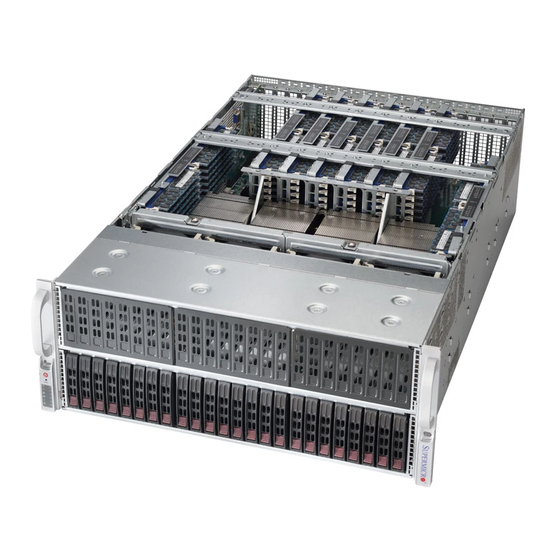
SUPERSERVER 4048B-TR4FT USER'S MANUAL Figure 6-1. Front and Rear Chassis Views Control Panel Hard Drives (24) Power Supplies (4) I/O Ports Control Panel The control panel is located on the front left handle of the chassis. See Chapter 3 for details on the LEDs and the control panel buttons. -
Page 85: Installing Hard Drives
2. Use the handle to pull the drive and its carrier out of the chassis. Figure 6-2. Removing a Hard Drive Carrier Enterprise level hard disk drives are recommended for use in Supermicro chassis and servers. For information on recommended HDDs, visit the Supermicro Web site... - Page 86 SUPERSERVER 4048B-TR4FT USER'S MANUAL Installing a Hard Drive into a Drive Carrier 1. Insert a drive into the carrier with the PCB side facing down and the connector end toward the rear of the carrier. 2. Align the drive in the carrier so that the screw holes of both line up. Note that there are holes in the carrier marked “SATA”...
-
Page 87: Accessing The Inside Of The System
Chapter 6: Advanced Chassis Setup Accessing the Inside of the System Removing the Chassis Cover You will need to access the inside of the system to complete certain procedures such as replacing fans. Removing the Chassis Cover If working with componenets such as memory, processors or heatsinks, start by shutting the system down and disconnecting the AC power cord. -
Page 88: Installing The Air Shroud
SUPERSERVER 4048B-TR4FT USER'S MANUAL Installing the Air Shroud Air Shrouds Air shrouds concentrate airflow to maximize fan efficiency. The SC418 chassis air shrouds do not require screws to set them up. Installing the Air Shroud 1. Confirm that all six fans are in place and working properly. -
Page 89: Cooling System
Chapter 6: Advanced Chassis Setup Cooling System The SC418 chassis contains four 9-cm system fans that provide cooling for the chassis and three 8-cm exhaust fans at the rear of the chassis for expelling hot air. All fans are hot-swappable, there is no need to power down the system when replacing fans. - Page 90 SUPERSERVER 4048B-TR4FT USER'S MANUAL Replacing an Exhaust Fan 1. Determine which of the exhaust fans have failed. 2. Remove the cover from the chassis as described previously. 3. Lift the fan housing up and out of the chassis. 4. Remove the failed fan from the fan housing.
-
Page 91: Power Supply
Chapter 6: Advanced Chassis Setup Power Supply The 4048B-TR4FT has a redundant, high-efficiency 1620 Watt power supply. This power supply is auto-switching capable, enabling it to automatically sense and operate at a 100v to 240v input voltage. An amber light will be illuminated on the power supply when the power is off. An illuminated green light indicates that the power supply is operating. - Page 92 SUPERSERVER 4048B-TR4FT USER'S MANUAL Notes 6-10...
-
Page 93: Chapter 7 Bios
AMI BIOS setup utility. This setup utility can be accessed by pressing <Delete> at the appropriate time during system boot. Note: For AMI UEFI BIOS Recovery, please refer to the UEFI BIOS Recovery User Guide posted at http://www.supermicro.com/support/manuals/. -
Page 94: Starting The Setup Utility
SUPERSERVER 4048B-TR4FT USER'S MANUAL Starting the Setup Utility Normally, the only visible Power-On Self-Test (POST) routine is the memory test. As the memory is being tested, press the <Delete> key to enter the main menu of the AMI BIOS setup utility. From the main menu, you can access the other setup screens. -
Page 95: Advanced Setup Configurations
Chapter 7: BIOS Supermicro X10QBi Version This item displays the SMC version of the BIOS ROM used in this system. Build Date This item displays the date that the BIOS setup utility was built. Memory Information Total Memory This item displays the amount of memory that is available in the system. - Page 96 SUPERSERVER 4048B-TR4FT USER'S MANUAL AddOn ROM Display Mode Use this item to set the display mode for the Option ROM. Select Keep Current to use the current AddOn ROM Display setting. Select Force BIOS to use the Op- tion ROM display set by the system BIOS. The options are Force BIOS and Keep Current.
- Page 97 Chapter 7: BIOS system power after a power outage. Select Last State to allow the system to resume its last power state before a power outage. The options are Power On, Stay Off, and Last State. CPU Configuration This submenu displays the following CPU information as detected by the BIOS. It also allows the user to configure CPU settings.
- Page 98 SUPERSERVER 4048B-TR4FT USER'S MANUAL Cores Enabled Use this item to set the number of CPU cores to be enabled in your system. Enter "0" to enable all cores. There are 14 cores available in the system. The default setting is 0.
- Page 99 Chapter 7: BIOS DCU (Data Cache Unit) Streamer Prefetcher (Available when supported by the CPU) If set to Enable, the DCU Streamer Prefetcher will prefetch data streams from the cache memory to the DCU to speed up data accessing and processing for CPU performance enhancement.
- Page 100 SUPERSERVER 4048B-TR4FT USER'S MANUAL Down Stream PECI (Platform Environment Control Interface) Select Enable to allow the client server to interact with the host server directly to achieve better host-client communication in the PECI platform, which will result in power saving and energy use efficiency. The options are Disable and Enable.
- Page 101 Chapter 7: BIOS C2C3TT (C2-to-C3 Transaction Timer) This item is used to set the transaction timer from the C2 state to the C3 state. Enter 0 for Auto, which will allow the BIOS to configure the transaction timer automatically. The Default setting is 0 (Auto). Package C State limit Use this item to set the limit on the C-State package register.
- Page 102 SUPERSERVER 4048B-TR4FT USER'S MANUAL Energy/Performance Bias Setting Use this item to select an appropriate fan setting to achieve maximum system performance (with maximum cooling) or maximum energy efficiency with maxi- mum power saving). The fan speeds are controlled by the firmware management via IPMI 2.0.
- Page 103 Chapter 7: BIOS Link Speed Use this item to select the PCI-E link speed for the PCI-E port specified by the user. The options for CPU-PCH DMI port and are GEN1 (2.5 GT/s), GEN2 (5 GT/s), and Auto. The options for Onboard LAN port, CPU1 Slot1 x8 port, and CPU1 Slot2 x16 port are GEN1 (2.5 GT/s), GEN2 (5 GT/s), GEN3 (8 GT/s), and Auto.
- Page 104 SUPERSERVER 4048B-TR4FT USER'S MANUAL IIO3 Configuration CPU4 Slot8 x8/CPU4 Slot10 x8/CPU4 Slot11 x16 Use the items below to configure the PCI-E settings for a PCI-E port specified by the user. The following items will display: • PCI-E Port Link Status •...
- Page 105 Chapter 7: BIOS Interrupt Remapping Select Enable to support Interrupt Remapping to enhance system performance. The options are Enable and Disable. PCI Express Global Options Power Down Unused Ports Select Enable to power down the ports that are conneced. The options are Disable, Enable, HSX Disable Unused Ports (No IIO Clock Gating), and HSX Disable Unused Ports (IIO Clock Gating).
- Page 106 SUPERSERVER 4048B-TR4FT USER'S MANUAL Legacy VGA Socket Enter the VGA socket number (from 0-7) that will be used to support legacy VGA. The default setting is 0. QPI Per Socket Configuration CPU 0/CPU 1/CPU 2/CPU 3 Bus Resource Allocation Ratio Use this feature to set the bus resource-allocation ratio (from 0-8).
- Page 107 Chapter 7: BIOS Perbit (Per-bit) Deskew Training Select Enable for Perbit Deskew Training support, which will allow the memory controller to include various adjustable delay circuits in both Read and Write paths on a per-bit base for effective memory interface to maximize memory performance.
- Page 108 SUPERSERVER 4048B-TR4FT USER'S MANUAL Closed Loop Thermal Throttling Select Enabled to support Closed-Loop Thermal Throttling which will improve reliability and reduces CPU power consumption via automatic voltage control while the CPU are in idle states. The options are Disabled and Enabled.
- Page 109 Chapter 7: BIOS Memory Interleaving Use this feature to set the DIMM memory interleaving mood. The options are NUMA (1-way) Node Interleave, 2-way Node Interleave, 4-way Interleave, 8 Way Interleaving, Inter-socket, and Auto. Channel Interleaving Use this feature to set the DIMM channel interleaving mood. The options are Auto, 1-way Interleave, 2-way Interleave, 3-way Interleave, and 4-way Interleave.
- Page 110 SUPERSERVER 4048B-TR4FT USER'S MANUAL Memory Mirroring Select Enable to enable memory-mirroring support which will create a duplicate copy of the data stored in the memory to enhance data security. The options are Disable and Enable. South Bridge This feature is used to configure Intel South Bridge settings.
- Page 111 Chapter 7: BIOS Configure SATA As Use this feature to configure the SATA mode for a devices installed in the SATA port specified by the user. The options are IDE, AHCI and RAID. Software Feature Mask Configuration Low Power Device Detection Support Select Enabled for the low-power device to be detected by the BIOS.
- Page 112 SUPERSERVER 4048B-TR4FT USER'S MANUAL Select Enabled to allow the PCH to start a COMRESET initialization (from 0 to 1 on an edge detect) to the device. The options are Enabled and Disabled. SATA Device Type Use this feature to configure the SATA device type for the device installed on selected a SATA port for use of IDE mode, RAID mode or AHCI mode.
- Page 113 Chapter 7: BIOS Maximum Read Request Select Auto to allow the system BIOS to automatically set the maximum Read Request size for a PCI-E device to enhance system performance. The options are Auto, 128 Bytes, 256 Bytes, 512 Bytes, 1024 Bytes, 2048 Bytes, and 4096 Bytes. ASPM Support This feature allows the user to set the Active State Power Management (ASPM) level for a PCI-E device.
- Page 114 SUPERSERVER 4048B-TR4FT USER'S MANUAL Onboard LAN OpROM (Option ROM) Select Select iSCSI to use the iSCSI Option ROM to boot the computer using a iSCSI network device. Select PXE (Preboot Execution Environment) to use an PXE Option ROM to boot the computer using a PXE network device. The options are iSCSI and PXE.
- Page 115 Chapter 7: BIOS Pending Operation Use this item to schedule an operation for the security device. The options are None, Enable Take Ownership, Disable Take Ownership, and TPM Clear. Note: The computer will reboot in order to execute the pending commands and change the state of the security device.
- Page 116 SUPERSERVER 4048B-TR4FT USER'S MANUAL Super IO Configuration Super IO Chip: This item displays the Super IO chip used in the motherboard. Serial Port 1 Configuration Serial Port Select Enabled to enable a serial port specified by the user. The options are En- abled and Disabled.
- Page 117 Chapter 7: BIOS unavailable. The options are Auto, O=2F8h; IRQ=3; IO=3F8h; IRQ=3, 4, 5, 6, 7, 10, 11, 12; IO=2F8h; IRQ=3, 4, 5, 6, 7, 10, 11, 12; IO=3E8h; IRQ=3, 4, 5, 6, 7, 10, 11, 12; IO=2E8h; IRQ=IRQ=3, 4, 5, 6, 7, 10, 11, 12. Serial Port 2 Attribute Use this feature to select the attribute for this serial port.
- Page 118 SUPERSERVER 4048B-TR4FT USER'S MANUAL acter Set. Select VT-UTF8 to use UTF8 encoding to map Unicode characters into one or more bytes. The options are ANSI, VT100, VT100+, and VT-UTF8. Bits Per second Use this feature to set the transmission speed for a serial port used in Console Redirection.
- Page 119 Chapter 7: BIOS Resolution 100x31 Select Enabled for extended-terminal resolution support. The options are Dis- abled and Enabled. Legacy OS Redirection Resolution Use this feature to select the number of rows and columns used in Console Redirection for legacy OS support. The options are 80x24 and 80x25. Putty KeyPad This feature selects Function Keys and KeyPad settings for Putty, which is a terminal emulator designed for the Windows OS.
- Page 120 SUPERSERVER 4048B-TR4FT USER'S MANUAL character set. Select VT-UTF8 to use UTF8 encoding to map Unicode characters into one or more bytes. The options are ANSI, VT100, VT100+, and VT-UTF8. Bits Per Second This item sets the transmission speed for a serial port used in Console Redirec- tion.
-
Page 121: Event Logs
Chapter 7: BIOS Event Logs Use this feature to configure Event Log settings. Change SMBIOS Event Log Settings This feature allows the user to configure SMBIOS Event settings. Enabling/Disabling Options SMBIOS Event Log Select Enabled to enable SMBIOS (System Management BIOS) Event Logging during system boot. - Page 122 SUPERSERVER 4048B-TR4FT USER'S MANUAL SMBIOS Event Log Standard Settings Log System Boot Event Select Enabled to log system boot events. The options are Disabled and Enabled. MECI (Multiple Event Count Increment) Enter the increment value for the multiple event counter. Enter a number between 1 to 255.
-
Page 123: Ipmi
Chapter 7: BIOS IPMI Select the IPMI (Intelligent Platform Management Interface) tab to access the fol- lowing submenu items. These items indicates your system IPMI firmware revision number and status. • IPMI Firmware Revision • IPMI Statu System Event Log ... - Page 124 SUPERSERVER 4048B-TR4FT USER'S MANUAL When SEL is Full This feature allows the user to determine what the AMI BIOS should do when the system event log is full. Select Erase Immediately to erase all events in the log when the system event log is full. The options are Do Nothing and Erase Immediately.
-
Page 125: Security
Chapter 7: BIOS Security This menu allows the user to configure the following security settings for the system. Administrator Password Use this item to set the administrator password which is required to enter the BIOS setup utility. The length of the password should be from 3 characters to 20 characters long. -
Page 126: Boot
SUPERSERVER 4048B-TR4FT USER'S MANUAL Boot This submenu allows the user to configure the following boot settings for the system. Boot Mood Select Use this item to configure boot mood select settings for the machine. The options are Legacy, UEFI, and Dual. -
Page 127: Save & Exit
Chapter 7: BIOS Hard Disk Drive BBS Priorities This item sets the boot sequence of available hard disk drives. • Boot Option #1 Network Drive BBS Priorities • Boot Option #1 UEFI Application Boot Priorities • Boot Option #1 Save &... - Page 128 SUPERSERVER 4048B-TR4FT USER'S MANUAL Save Changes and Exit When completing the system configuration changes, select this option to save the changes and exit from the BIOS setup utility. When a dialog box appears, asking you if you want to save configuration and exit, select Yes to save the changes and exit from the BIOS setup utility.
- Page 129 Chapter 7: BIOS Restore User Defaults Select this feature and press <Enter> to load the user's defaults previously saved in the system. When the dialog box appears, asking you if you want to restore user's defaults, select Yes to restore the user's defaults previously saved in the system, or select No to abandon the user's defaults that were previously saved.
- Page 130 SUPERSERVER 4048B-TR4FT USER'S MANUAL Notes 7-38...
-
Page 131: Appendix A Bios Error Beep Codes
Appendix A: BIOS Error Beep Codes Appendix A BIOS Error Beep Codes During the POST (Power-On Self-Test) routines, which are performed at each system boot, errors may occur. Non-fatal errors are those which, in most cases, allow the system to continue to boot. - Page 132 SUPERSERVER 4048B-TR4FT USER'S MANUAL Notes...
-
Page 133: Appendix B System Specifications
24 hot-swap drive bays to house 2.5" hard drives. Note: An additional backplane may be installed to support a total of up to 48 2.5" drives. PCI Expansion The SuperServer 4048B-TR4FT has four PCI Express 3.0 x16 slots and seven PCI Express 3.0 x8 slots available. Boards One X10QBi baseboard (proprietary form factor) Dimensions: (LxW) 19 x 17 in. - Page 134 SUPERSERVER 4048B-TR4FT USER'S MANUAL Chassis SC418XTA-R3240B (4U rackmount) Dimensions: (WxHxD) 7 x 17.2 x 31.3 in. (178 x 437 x 795 mm) Weight Gross (Bare Bone): 150 lbs. (68 kg.) System Cooling The system has four 9-cm system fans and three 8-cm rear exhaust fans (fan...
- Page 135 Appendix B: System Specifications Regulatory Compliance Electromagnetic Emissions: FCC Class A, EN 55022 Class A, EN 61000-3-2/-3- 3, CISPR 22 Class A Electromagnetic Immunity: EN 55024/CISPR 24, (EN 61000-4-2, EN 61000-4-3, EN 61000-4-4, EN 61000-4-5, EN 61000-4-6, EN 61000-4-8, EN 61000-4-11) Safety: CSA/EN/IEC/UL 60950-1 Compliant, UL or CSA Listed (USA and Canada), CE Marking (Europe) California Best Management Practices Regulations for Perchlorate Materials:...
- Page 136 SUPERSERVER 4048B-TR4FT USER'S MANUAL (continued from front) The products sold by Supermicro are not intended for and will not be used in life support systems, medical equipment, nuclear facilities or systems, aircraft, aircraft devices, aircraft/emergency communication devices or other critical systems whose failure to perform be reasonably expected to result in significant injury or loss of life or catastrophic property damage.
Need help?
Do you have a question about the 4048B-TR4FT and is the answer not in the manual?
Questions and answers