Table of Contents
Advertisement
Quick Links
Advertisement
Table of Contents

Related Manuals for Supermicro SUPERSERVER 4029GP-TVRT


Summary of Contents for Supermicro SUPERSERVER 4029GP-TVRT
- Page 1 SuperServer ® 4029GP-TVRT USER’S MANUAL Revision 1.0b...
- Page 2 State of California, USA. The State of California, County of Santa Clara shall be the exclusive venue for the resolution of any such disputes. Supermicro's total liability for all claims will not exceed the price paid for the hardware product.
- Page 3 If you have any questions, please contact our support team at: support@supermicro.com This manual may be periodically updated without notice. Please check the Supermicro website for possible updates to the manual revision level. Secure Data Deletion A secure data deletion tool designed to fully erase all data from storage devices can be found on our website: https://www.supermicro.com/about/policies/disclaimer.cfm?url=/wftp/utility/...
-
Page 4: Table Of Contents
SuperServer 4029GP-TVRT User's Manual Contents Chapter 1 Introduction 1.1 Overview ..........................8 1.2 Unpacking the System ......................8 1.3 System Features ........................9 1.4 Server Chassis Features ....................10 Control Panel ........................10 Front Features ........................11 Rear Features ........................12 1.5 Motherboard Layout ......................13 Quick Reference ......................14 System Block Diagram ......................16... - Page 5 Contents 3.3 Motherboard Components ....................27 Processor and Heatsink Installation ..................27 The Processor Carrier Assembly ...................27 Overview of the Processor Heatsink Module ..............28 Creating the Processor Carrier Assembly ..............29 Assembling the Processor Heatsink Module ..............30 Preparing the CPU Socket for Installation..............31 Installing the Processor Heatsink Module ..............32 Memory Installation ......................33 Memory Support ......................33...
- Page 6 SuperServer 4029GP-TVRT User's Manual Chapter 5 Software 5.1 Microsoft Windows OS Installation ..................65 5.2 Driver Installation ........................67 5.3 SuperDoctor 5 ........................68 ® 5.4 IPMI ............................69 Chapter 6 BIOS 6.1 Introduction .........................70 Starting BIOS Setup Utility ....................70 6.2 Main Setup .........................70 6.3 Advanced Setup Configurations ..................72...
- Page 7 Super Micro Computer, Inc. 980 Rock Ave. San Jose, CA 95131 U.S.A. Tel: +1 (408) 503-8000 Fax: +1 (408) 503-8008 Email: marketing@supermicro.com (General Information) support@supermicro.com (Technical Support) Website: www.supermicro.com Europe Address: Super Micro Computer B.V. Het Sterrenbeeld 28, 5215 ML...
-
Page 8: Overview
SuperServer 4029GP-TVRT User's Manual Chapter 1 Introduction 1.1 Overview This chapter provides a brief outline of the functions and features of the 4029GP-TVRT system, based on the X11DGO-T motherboard and the R422BG-1 chassis. In addition to the motherboard and chassis, several parts included with the system are listed below. -
Page 9: System Features
Dual Intel Xeon 82xx/62xx/52xx or 81xx/61xx/51xx processors (in Socket P (LGA 3647)) (Intel Xeon Processor Scalable Family). For the latest CPU/memory updates, refer to our website at http://www.supermicro.com/products/motherboard/Xeon/C620/X11DGO-T.cfm. Memory In twenty-four slots, up to 12 TB of 3DS Load Reduced DIMM (3DS LRDIMM), Load Reduced DIMM (LRDIMM), 3DS Registered DIMM (3DS RDIMM), Registered DIMM (RDIMM);... -
Page 10: Server Chassis Features
SuperServer 4029GP-TVRT User's Manual 1.4 Server Chassis Features Control Panel The switches and indicator lights located on the control panel are described below. Figure 1-1. Control Panel View Control Panel Features Item Feature Description This button is dual function, depending on the JBMC_BTN jumper (see Chapter 4). -
Page 11: Front Features
Chapter 1: Introduction Front Features The R422BG-1 is a 4U chassis with a 2U GPU tray on top and the 2U motherboard and drive tray on the bottom. GPU Tray Motherboard Tray Figure 1-2. Chassis Front View Front Chassis Features Item Feature Description... -
Page 12: Rear Features
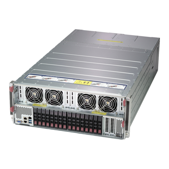
SuperServer 4029GP-TVRT User's Manual Graphic Processor Unit Tray Motherboard Tray Figure 1-4. Removable Chassis Trays Rear Features SCALE 1:2 The illustration below shows the features included on the rear of the chassis. Figure 1-5. Chassis Rear View Rear Chassis Features... -
Page 13: Motherboard Layout
Chapter 1: Introduction 1.5 Motherboard Layout Below is a layout of the X11DGO-T with jumper, connector and LED locations shown. See the table on the following page for descriptions. For detailed descriptions, pinout information and jumper settings, refer to Chapter 4. Midplane Interface JPWR2 JPWR1... -
Page 14: Quick Reference
SuperServer 4029GP-TVRT User's Manual Quick Reference Jumper Description Default Setting Pins 1-2 (SW2: used as BMC UID: Default), Pins 2-3 JBMC_BTN1 BMC Button Jumper (SW2: for BMC Reset) JBT1 CMOS Clear Open (Normal) JPG1 VGA Enable Pins 1-2 (Enabled) JPL1... - Page 15 Chapter 1: Introduction Connector Description Front Accessible VGA port Description State: Status HDD_LED1 HDD Activity LED Blinking Green: HDD active LED1 M.2 Slot1 (M.2-P1) Activity LED On: M.2 Slot 1 active LED2 M.2 Slot2 (M.2-P2) Activity LED On: M.2 Slot 2 active LEDM1 (LEDBMC) BMC Heartbeat LED Blinking Green: BMC normal...
-
Page 16: System Block Diagram
SuperServer 4029GP-TVRT User's Manual System Block Diagram #F-2 #M-2 X11DGO-T Rev.1.00 #F-1 #M-1 #E-2 #L-2 #E-1 #L-1 #D-2 #K-2 #D-1 10.4/11.2G #K-1 #C-2 #J-2 #C-1 #J-1 #B-2 #H-2 #B-1 #H-1 #A-2 #G-2 CPU2 CPU1 #A-1 #G-1 DMI3 DMI3 PCI-E X16 G3... -
Page 17: Gpu Add-On Module
Chapter 1: Introduction GPU Add-on Module The system supports eight Tesla SXM2 V100 GPUs installed on the X10DGO-SXMV add-on module which is connected to the motherboard by a midplane. The X10DGO-SXMV is connected through Nvidia’s Cube Mesh NVLINK architecture. Direct connection between all GPUs are single NVlink (25 GB/s). -
Page 18: Chapter 2 Server Installation
SuperServer 4029GP-TVRT User's Manual Chapter 2 Server Installation 2.1 Overview This chapter provides advice and instructions for mounting your system in a server rack. If your system is not already fully integrated with processors, system memory etc., refer to Chapter 4 for details on installing those specific components. -
Page 19: Server Precautions
Chapter 2: Server Installation • In single rack installations, stabilizers should be attached to the rack. In multiple rack in- stallations, the racks should be coupled together. • Always make sure the rack is stable before extending a server or other component from the rack. -
Page 20: Circuit Overloading
SuperServer 4029GP-TVRT User's Manual Circuit Overloading Consideration should be given to the connection of the equipment to the power supply circuitry and the effect that any possible overloading of circuits might have on overcurrent protection and power supply wiring. Appropriate consideration of equipment nameplate ratings should be used when addressing this concern. -
Page 21: Procedure For Rack Mounting
Chapter 2: Server Installation 2-3 Procedure for Rack Mounting This section provides information on installing the chassis into a rack unit with the rails provided. There are a variety of rack units on the market, so the assembly procedure may differ slightly. -
Page 22: Installing The Rails On A Rack
SuperServer 4029GP-TVRT User's Manual Installing the Rails on a Rack Installing the Rails 1. Loosen the adjusting screw to allow the rear section to slide in the front section.. 2. Push the small hooks on the front section of the rail into the holes on the front post of the rack and then down, until the spring-loaded pegs snap into the rack holes. -
Page 23: Chassis Installation
Chapter 2: Server Installation Chassis Installation Slide the chassis into the rack so that the bottom of the chassis slide onto the bottom lip of the rail. Figure 2-3. Sliding the Chassis into the Rack Stability hazard. The rack stabilizing mechanism must be in place, or the rack must be bolted to the floor before you slide the unit out for servicing. -
Page 24: Chapter 3 Maintenance And Component Installation
SuperServer 4029GP-TVRT User's Manual Chapter 3 Maintenance and Component Installation This chapter provides instructions on installing and replacing main system components. To prevent compatibility issues, only use components that match the specifications and/or part numbers given. Installation or replacement of most components require that power first be removed from the system. -
Page 25: Accessing The System
Chapter 3: Maintenance and Component Installation 3.2 Accessing the System Internal components are accessible by removing the appropriate tray. Removing a Component Tray 1. Begin by removing power from the system as described in Section 3.1. 2. On the outside edges of the tray, pull down on both release levers and pull out the tray. Release Lever Release Lever Release Lever... -
Page 26: Removing The Chassis Tray Covers
SuperServer 4029GP-TVRT User's Manual Removing the Chassis Tray Covers The motherboard tray and the GPU tray each have a cover that can be removed to access internal components. Removing the Tray Cover • Slide the release buttons on both sides of the cover toward the middle of the tray and lift the cover. -
Page 27: Motherboard Components
Thermal grease is pre-applied on a new heatsink. No additional thermal grease is needed. • Refer to the Supermicro website for updates on processor support. • All graphics in this manual are for illustration only. Your components may look different. -
Page 28: Overview Of The Processor Heatsink Module
SuperServer 4029GP-TVRT User's Manual Overview of the Processor Heatsink Module The Processor Heatsink Module (PHM) contains a heatsink, a processor carrier, and the processor. Heatsink with Thermal Grease Processor Carrier Processor Processor Heatsink Module Bottom View... -
Page 29: Creating The Processor Carrier Assembly
Chapter 3: Maintenance and Component Installation Creating the Processor Carrier Assembly To install a processor into the processor carrier, follow the steps below: 1. Hold the processor with the LGA lands (gold contacts) facing up. Locate the small, gold triangle in the corner of the processor and the corresponding hollowed triangle on the processor carrier. -
Page 30: Assembling The Processor Heatsink Module
SuperServer 4029GP-TVRT User's Manual Assembling the Processor Heatsink Module After creating the processor carrier assembly, mount it onto the heatsink to create the processor heatsink module (PHM): 1. Note the label on top of the heatsink, which marks the heatsink mounting holes as 1, 2, 3, and 4. -
Page 31: Preparing The Cpu Socket For Installation
Chapter 3: Maintenance and Component Installation Preparing the CPU Socket for Installation This motherboard comes with a plastic protective cover on the CPU socket. Remove it carefully to install the Processor Heatsink Module (PHM). CPU Socket with Plastic Protective Cover Remove the plastic protective cover from the CPU socket. -
Page 32: Installing The Processor Heatsink Module
SuperServer 4029GP-TVRT User's Manual Installing the Processor Heatsink Module After assembling the Processor Heatsink Module (PHM), install it onto the CPU socket: 1. Align hole 1 of the heatsink with the printed triangle on the CPU socket. See the left image below. -
Page 33: Memory Installation
*4Gb DRAM density is only supported on speeds up to 2666 MT/s **Only the 82xx and 62xx series support 2933 MT/s; for other processors, 2933 memory will be down-clocked to whatever speed the CPUs support. Check the Supermicro website for possible updates to memory support. -
Page 34: Memory Population Guidelines
Then, if using two DIMMs per channel, install the second DIMM in the black slot. The following memory population sequence table was created based on guidelines provided by Intel to support Supermicro motherboards. The diagram is for illustrative purposes; your motherboard may look different. - Page 35 Chapter 3: Maintenance and Component Installation Memory Population for the X11 DP Motherboard, 24 DIMM Slots CPUs/DIMMs Memory Population Sequence 1 CPU & 1 DIMM CPU1: P1-DIMMA1 1 CPU & 2 DIMMs CPU1: P1-DIMMA1/P1-DIMMD1 1 CPU & 3 DIMMs CPU1: P1-DIMMC1/P1-DIMMB1/P1-DIMMA1 1 CPU &...
- Page 36 SuperServer 4029GP-TVRT User's Manual Pin 1 CPU1 CPU2...
-
Page 37: Dcpmm Population Table (24 Slots) Based On The 82Xx/62Xx/52Xx/42Xx
Chapter 3: Maintenance and Component Installation DCPMM Population Table (24 Slots) based on the 82xx/62xx/52xx/42xx Symmetric Population for Each CPU DCP & P1/P2- P1/P2- P1/P2- P1/P2- P1/P2- P1/P2- P1/P2- P1/P2- P1/P2- P1/P2- P1/P2- P1/P2- Channel Modes DIMMs DIMMF1 DIMMF2 DIMME1 DIMME2 DIMMD1 DIMMD2... - Page 38 SuperServer 4029GP-TVRT User's Manual • For each individual population, rearrangements between channels are allowed as long as the resulting population is compliant with the PDG rules for the 82xx/62xx/52xx/42xx platform. • For each individual population, use the same DDR4 DIMM in all slots.
-
Page 39: Installing Memory
Chapter 3: Maintenance and Component Installation Installing Memory ESD Precautions Electrostatic Discharge (ESD) can damage electronic com ponents including memory modules. To avoid damaging DIMM modules, it is important to handle them carefully. The following measures are generally sufficient. • Use a grounded wrist strap designed to prevent static discharge. -
Page 40: Motherboard Battery
SuperServer 4029GP-TVRT User's Manual Motherboard Battery The motherboard uses non-volatile memory to retain system information when system power is removed. This memory is powered by a lithium battery residing on the motherboard. Replacing the Battery Begin by removing power from the system as described in Section 3.1 and remove the cover as described in Section 3.2.. -
Page 41: Graphic Processor Units
Chapter 3: Maintenance and Component Installation 3.4 Graphic Processor Units The system supports eight Volta SXM2 V100 GPUs installed on the X10DGO-SXMV add- on module mounted on the the GPU chassis tray and connected to the motherboard by the bridge boards. GPU Mapping The GPU numbering shows differently, depending on the interface. -
Page 42: Installing A Gpu
SuperServer 4029GP-TVRT User's Manual Installing a GPU 1. Power down the system, pull the GPU chassis tray from the main chassis and remove the cover. 2. Remove all the plastic socket covers on both the GPU and the add-on module. - Page 43 Chapter 3: Maintenance and Component Installation Figure 3-6. GPU Heatsinks Installed...
-
Page 44: Gpu Air Shrouds
SuperServer 4029GP-TVRT User's Manual GPU Air Shrouds Air shrouds concentrate airflow to maximize fan efficiency. Installing the GPU Air Shroud 1. Power down the system, pull the GPU chassis tray from the main chassis and remove the cover. 2. Noting the front and rear sides of the air shroud, insert the sides of the air shroud between the chassis and GPU1 and GPU8. -
Page 45: Chassis Components
Depending on the number of NVMe drives, one or two PCI-E connectors are used, and therefore not available for expansion cards. Note: Enterprise level hard disk drives are recommended for use in Supermicro servers. For information on recommended HDDs, visit the Supermicro website at http://www.supermicro. -
Page 46: Installing Drives
SuperServer 4029GP-TVRT User's Manual Drive Carrier LED Indicators Color Blinking Pattern Behavior for Device Activity Blue Solid On SAS/NVMe drive installed Blue Blinking I/O activity Status Solid On Failure of drive with RSTe support Blinking at 1 Hz Rebuild drive with RSTe support... - Page 47 Chapter 3: Maintenance and Component Installation Installing a Storage Drive 1. Remove the dummy drive from the carrier by removing the screws. 2. Insert a drive into the carrier with the PCB side facing down and the connector end toward the rear of the carrier. Align the drive in the carrier so that the screw holes line up.
-
Page 48: Installing Nvme Drives
SuperServer 4029GP-TVRT User's Manual Installing NVMe Drives OCuLink cables (CBL-SAST-1021) are required to support NVMe drives. OCuLink, x8 to two x4 "Y" cable x4 (7:4) to NVMe x8 (7:0) to CPU x4 (3:0) to NVMe Master Figure 3-11. OCuLink Cable for NVMe... - Page 49 Chapter 3: Maintenance and Component Installation Figure 3-12. NVMe Cabling Diagram Configuring NVMe 1. Connect cable(s) as needed from the motherboard to the backplane as shown in the diagram above. One OCuLink cable is required for each pair of NVMe drives. 2.
- Page 50 SuperServer 4029GP-TVRT User's Manual b. VMD configuration: Enable VMD mode and corresponding port (3A, 3B), and Save and Exit. Advanced > Chipset Config > North Bridge > IIO Config > VMD techology c. VMD Management (Re-enter to setup menu and you may get the two disks.) Advanced >...
-
Page 51: Hot-Swap For Nvme Drives
Chapter 3: Maintenance and Component Installation Hot-Swap for NVMe Drives Supermicro servers support NVMe surprise hot-swap. For even better data security, NVMe orderly hot-swap is recommended. NVMe drives can be ejected and replaced remotely using IPMI. Note: If you are using VROC, see the VROC appendix in this manual instead. -
Page 52: Checking The Temperature Of An Nvme Drive
SuperServer 4029GP-TVRT User's Manual Checking the Temperature of an NVMe Drive There are two ways to check using IPMI. Checking a Drive • IPMI > Server Health > NVMe SSD – Shows the temperatures of all NVMe drives, as in Figure 3-4. -
Page 53: Replacing Fans
Chapter 3: Maintenance and Component Installation Replacing Fans The chassis contains eight 9-cm exhaust fans that provide cooling for the system. There is no need to power down the system when switching fans. Changing a System Fan 1. Determine which fan has failed using IPMI or observation. 2. -
Page 54: Power Supply
The failed power module can be replaced without powering-down the system. Replace with the same model. Replacement modules can be ordered directly from Supermicro. An amber light on the power supply is illuminated when the power is switched off. An green light indicates that the power supply is operating. -
Page 55: Expansion Cards
Chapter 3: Maintenance and Component Installation Expansion Cards The X11DGO-T system motherboard offers two PCI-E expansion card slots. See restrictions if the system includes NVMe (Storage Drives section). The X10DGO-SXMV GPU board offers four additional PCI-E slots, supported by PLX, linked to the GPUs. All expansion cards are x16 low profile. - Page 56 SuperServer 4029GP-TVRT User's Manual Expansion Card Expansion Cards (2) Expansion Card Figure 3-14. Expansion Cards on GPU Board (supported by PLX)
-
Page 57: Chapter 4 Motherboard Connections
Chapter 4: Motherboard Connections Chapter 4 Motherboard Connections This section describes the connections on the X11DGO-T motherboard and provides pinout definitions. Note that depending on how the system is configured, not all connections are required. The LEDs on the motherboard are also described here. A motherboard layout indicating component locations may be found in Chapter 1. -
Page 58: Headers And Connectors
SuperServer 4029GP-TVRT User's Manual 4.2 Headers and Connectors Fan Headers This motherboard has two fan headers (FAN1/FAN2) for system cooling. These are 4-pin fan headers, which are backward compatible with traditional 3-pin fans. The onboard fan speed is controlled by Thermal Management (via Hardware Monitoring) in the IPMI interface. For best thermal management, use all 4-pin fans. - Page 59 Chapter 4: Motherboard Connections Serial Port A serial port (COM1) is located next to the power connector (JPW12) on the motherboard. The COM port header provides serial communication support. CN Connectors (CN10-17) CN connectors are used to connect PCI buses from processors to PCI-E slots using OCuLink x8 or x4 Y cables.
-
Page 60: Ports
SuperServer 4029GP-TVRT User's Manual 4.3 Ports Input/Output Ports Description Description USB 1 (USB 3.0) LAN1 USB 2 (USB 3.0) LAN2 IPMI LAN Figure 4-1. Front Input/Output Ports... -
Page 61: Jumpers
Chapter 4: Motherboard Connections 4.4 Jumpers Explanation of Jumpers To modify the operation of the motherboard, jumpers are used to choose between optional settings. Jumpers create shorts between two pins to change the function associated with it. Pin 1 is identified with a square solder pad on the printed circuit board. See the motherboard layout page for jumper locations. - Page 62 SuperServer 4029GP-TVRT User's Manual LAN1/LAN2 Enable/Disable Use jumper JPL1 to enable or disable LAN Port1 and LAN Port2. The default setting is Enabled. LAN1/LAN2 Enable/Disable Jumper Settings Jumper Setting Definition Pins 1-2 Enabled Pins 2-3 Disabled VGA Port Enable/Disable Jumper JPG1 is used to enable or disable the VGA port on the I/O back panel. Close pin 1 and pin 2 for VGA support.
- Page 63 Chapter 4: Motherboard Connections Watch Dog JWD controls the Watch Dog function. Watch Dog is a monitor that can reboot the system when a software application hangs. Jumping pins 1-2 will cause Watch Dog to reset the system if an application hangs. Jumping pins 2-3 will generate a non-maskable interrupt signal for the application that hangs.
-
Page 64: Led Indicators
SuperServer 4029GP-TVRT User's Manual 4.5 LED Indicators LAN LEDs The Ethernet ports each have two LEDs. One LED indicates activity when flashing, while the other LED may be green, amber or off to indicate the speed of the connection. LAN 1/2... -
Page 65: Chapter 5 Software
USB/SATA DVD drive, or a USB flash drive, or the IPMI KVM console. 2. Retrieve the proper RST/RSTe driver. Go to the Supermicro web page for your motherboard and click on "Download the Latest Drivers and Utilities", select the proper driver, and copy it to a USB flash drive. - Page 66 SuperServer 4029GP-TVRT User's Manual 4. During Windows Setup, continue to the dialog where you select the drives on which to install Windows. If the disk you want to use is not listed, click on “Load driver” link at the bottom left corner.
-
Page 67: Driver Installation
The Supermicro website contains drivers and utilities for your system at https://www. supermicro.com/wftp/driver. Some of these must be installed, such as the chipset driver. After accessing the website, go into the CDR_Images (in the parent directory of the above link) and locate the ISO file for your motherboard. Download this file to to a USB flash drive or a DVD. -
Page 68: Superdoctor ® 5
5.3 SuperDoctor ® The Supermicro SuperDoctor 5 is a program that functions in a command-line or web-based interface for Windows and Linux operating systems. The program monitors such system health information as CPU temperature, system voltages, system power consumption, fan speed, and provides alerts via email or Simple Network Management Protocol (SNMP). -
Page 69: Ipmi
BIOS settings that are related to IPMI. For general documentation and information on IPMI, visit our website at: http://www.supermicro.com/products/nfo/IPMI.cfm. BMC ADMIN User Password For security, each system is assigned a unique default BMC password for the ADMIN user. -
Page 70: Chapter 6 Bios
SuperServer 4029GP-TVRT User's Manual Chapter 6 BIOS 6.1 Introduction This chapter describes the AMI BIOS setup utility for the X11DGO-T and provides the instructions on navigating the setup screens. The BIOS is stored in a Flash EEPROM and can be updated. - Page 71 HH:MM:SS format. Note: The time is in the 24-hour format. For example, 5:30 P.M. appears as 17:30:00. The date's default value is 01/01/2016 after RTC reset. Supermicro X11DGO-T (Motherboard model) BIOS Version Build Date (of the BIOS) CPLD (Complex Programmable Logic Device) Version: This item displays the CPLD version used in the system.
-
Page 72: Advanced Setup Configurations
SuperServer 4029GP-TVRT User's Manual 6.3 Advanced Setup Configurations Use the arrow keys to select the Advanced tab and press <Enter> to access the submenu items. Caution: Take caution when changing the Advanced settings. An incorrect value, a very high DRAM frequency, or an incorrect DRAM timing setting may make the system unstable. If this occurs, revert to the manufacture default settings. - Page 73 Chapter 6: BIOS Bootup NumLock State Use this feature to set the Power-on state for the Numlock key. The options are Off and On. Wait For 'F1' If Error Select Enabled to force the system to wait until the 'F1' key is pressed if an error occurs. The options are Disabled and Enabled.
- Page 74 SuperServer 4029GP-TVRT User's Manual CPU Configuration Warning: Setting the wrong values in the following sections may cause the system to malfunc- tion. Processor Configuration The following CPU information will be displayed: • Processor BSP Revision • Processor Socket •...
- Page 75 Chapter 6: BIOS PPIN Control Select Unlock/Enable to use the Protected-Processor Inventory Number (PPIN) in the system. The options are Unlock/Enable and Unlock/Disable. Hardware Prefetcher (Available when supported by the CPU) If this feature is set to Enable, the hardware prefetcher will prefetch streams of data and instructions from the main memory to the Level 2 (L2) cache to improve CPU performance.
- Page 76 SuperServer 4029GP-TVRT User's Manual Advanced Power Management Configuration Power Technology Select Energy Efficient to support power-saving mode. Select Custom to customize system power settings. Select Disabled to disable power-saving settings. The options are Disable, Energy Efficient, and Custom. Power Performance Tuning (Available when "Power Technology" is set to Custom) Select BIOS to allow the system BIOS to configure the Power-Performance Tuning BIAS setting below.
- Page 77 Chapter 6: BIOS Hardware PM (Power Management) State Control Hardware P-States If this feature is set to Disable, the hardware power management will choose a P-state setting for the system based on an OS request. If this feature is set to Native Mode, the hardware power management will choose a P-state setting based on OS guidance.
- Page 78 SuperServer 4029GP-TVRT User's Manual UPI (Ultra Path Interconnect) General Configuration This section displays the following UPI General Configuration information: • Number of CPU • Number of Active UPI Link • Current UPI Link Speed • Current UPI Link Frequency •...
- Page 79 Chapter 6: BIOS Stale AtoS (A to S) Select Enable to remove the contents and the structures of the files that are no longer needed in the remote host server but are still in use by the local client machine from Directory A to Directory S in the NFS (Network File System) to optimize system performance.
- Page 80 SuperServer 4029GP-TVRT User's Manual • P2DIMMA1/P2DIMMA2; P2DIMMB1/P2DIMMB2; P1DIMMC1/ P2DIMMC2, P2DIMMD1/ P1DIMMD2; P2DIMME1/P2DIMME2; P2DIMMF1/P2DIMMF2 Memory RAS (Reliability_Availability_Serviceability) Configuration Use this submenu to configure the following Memory RAS settings: Mirror Mode Use this feature to configure the mirror mode settings for all 1LM/2LM memory modules installed in the system, which will create a duplicate copy of data stored in the memory to increase memory security, but it will reduce the memory capacity into half.
- Page 81 Chapter 6: BIOS every 16K cycles if there is no delay caused by internal processing. By using this method, roughly 64 GB of memory behind the IO hub will be scrubbed every day. The options are Enable and Disable. Patrol Scrub Interval Use this item to specify the number of hours (between 0 to 24) required for the system to complete a full patrol scrubbing.
- Page 82 SuperServer 4029GP-TVRT User's Manual Socket 0 PCI-E Br0D00F0 - Port 0/DMI - Socket 0 PCI-E Br5D00F0 - MCP1 (Available for CPU 1 Configuration only) Link Speed This feature configures the link speed of a PCI-E port specified by the user. The options are Auto, Gen 1 (Generation 1) (2.5 GT/s), Gen 2 (Generation 2) (5 GT/s), and Gen 3...
- Page 83 Chapter 6: BIOS IOAT Configuration Disable TPH (TLP Processing Hint) TPH is used for data-tagging with a destination ID and a few important attributes. It can send critical data to a particular cache without writing through to memory. Select No in this item for TLP Processing Hint support, which will allow a "TPL request"...
- Page 84 SuperServer 4029GP-TVRT User's Manual Coherency Support (Non-Isoch) Select Enable for the Non-Iscoh VT-d engine to pass through DMA (Direct Memory Access) to enhance system performance. The options are Enable and Disable. Intel® VMD Technology Intel® VMD for CPU1 CN1/CN2...
- Page 85 Chapter 6: BIOS II0-PCI-E Express Global Options PCI-E Hot Plug Select Enable to support Hot-plugging for the selected PCI-E slots which will allow the user to replace the devices installed in the slots without shutting down the system. The options are Enable and Disabled.
- Page 86 SuperServer 4029GP-TVRT User's Manual Server ME (Management Engine) Configuration This feature displays the following system ME configuration settings. • General ME Configuration • Operational Firmware Version • Backup Firmware Version • Recovery Firmware Version • ME Firmware Status #1/ME Firmware Status #2 •...
- Page 87 Chapter 6: BIOS (I-)SATA Port 0 - SATA Port 7 Hot Plug Select Enable to support Hot-plugging for the device installed on a selected SATA port which will allow the user to replace the device installed in the slot without shutting down the system.
- Page 88 SuperServer 4029GP-TVRT User's Manual Maximum Read Request Select Auto for the system BIOS to automatically set the maximum size for a read request for a PCI-E device to enhance system performance. The options are Auto, 128 Bytes, 256 Bytes, 512 Bytes, 1024 Bytes, 2048 Bytes, and 4096 Bytes.
- Page 89 Chapter 6: BIOS Ipv4 HTTP Support Select Enabled to enable Ipv4 HTTP boot support. If this feature is disabled, it will not create the Ipv4 HTTP boot option. The options are Enabled and Disabled. Ipv6 PXE Support Select Enabled to enable Ipv6 PXE boot support. If this feature is disabled, it will not create the Ipv6 PXE boot option.
- Page 90 SuperServer 4029GP-TVRT User's Manual Serial Port 2 Configuration Serial Port Select Enabled to enable the onboard serial port specified by the user. The options are Enabled and Disabled. Device Settings This feature displays the base I/O port address and the Interrupt Request address of a serial port specified by the user.
- Page 91 Chapter 6: BIOS Bits Per second Use this feature to set the transmission speed for a serial port used in Console Redirection. Make sure that the same speed is used in the host computer and the client computer. A lower transmission speed may be required for long and busy lines. The options are 9600, 19200, 38400, 57600 and 115200 (bits per second).
- Page 92 SuperServer 4029GP-TVRT User's Manual Putty KeyPad This feature selects Function Keys and KeyPad settings for Putty, which is a terminal emulator designed for the Windows OS. The options are VT100, LINUX, XTERMR6, SCO, ESCN, and VT400. Redirection After BIOS Post Use this feature to enable or disable legacy Console Redirection after BIOS POST.
- Page 93 Chapter 6: BIOS mark as a parity bit to be sent along with the data bits. Select Space to add a Space as a parity bit to be sent with your data bits. The options are None, Even, Odd, Mark and Space. Stop Bits A stop bit indicates the end of a serial data packet.
- Page 94 SuperServer 4029GP-TVRT User's Manual Legacy Console Redirection Settings Legacy Console Redirection Settings Use the feature to select the COM port to display redirection of Legacy OS and Legacy OPROM messages. The options are COM1 and SOL. Serial Port for Out-of-Band Management/Windows Emergency Management Services...
- Page 95 Chapter 6: BIOS ACPI Settings Use this feature to configure Advanced Configuration and Power Interface (ACPI) power management settings for your system. NUMA Support (Available when the OS supports this feature) Select Enabled to enable Non-Uniform Memory Access support to enhance system perfor- mance.
- Page 96 SuperServer 4029GP-TVRT User's Manual • Active PCR Banks • Available PCR Banks Pending Operation Use this feature to schedule a TPM-related operation to be performed by a security (TPM) device at the next system boot to enhance system data integrity. Your system will reboot to carry out a pending TPM operation.
- Page 97 "IIO Configuration" in the "Chipset/North Bridge" submenu). Note 2: For more information on TPM, please refer to the TPM manual at http://www. supermicro.com/manuals/other. Intel® Virtual RAID on CPU When this submenu is selected and the RAID devices are detected, the BIOS screen displays the following items: Intel®...
-
Page 98: Event Logs
SuperServer 4029GP-TVRT User's Manual 6.4 Event Logs Use this tab page to configure Event Log settings. Change SMBIOS Event Log Settings Enabling/Disabling Options SMBIOS Event Log Select Enabled to enable SMBIOS (System Management BIOS) Event Logging during system boot. The options are Enabled and Disabled. - Page 99 Chapter 6: BIOS SMBIOS Event Log Standard Settings Log System Boot Event Select Enabled to log system boot events. The options are Enabled and Disabled. MECI (Multiple Event Count Increment) Enter the increment value for the multiple event counter. Enter a number between 1 to 255. The default setting is 1.
-
Page 100: Ipmi
SuperServer 4029GP-TVRT User's Manual 6.5 IPMI Use this tab page to configure Intelligent Platform Management Interface (IPMI) settings. The following items will be displayed: • BMC Firmware Revision: This feature indicates the firmware revision of the BMC (Baseboard Management Controller) used in your system. - Page 101 Chapter 6: BIOS When SEL is Full This feature allows the user to specify what the BIOS should do when the system event log is full. Select Erase Immediately to erase all events in the log when the system event log is full.
- Page 102 SuperServer 4029GP-TVRT User's Manual *If the item "Update IPMI LAN Configuration" is set to Yes, the following items will display: IPMI LAN Selection Use this feature to select the type of the IPMI LAN. The options are Dedicated, Shared, and Failover.
-
Page 103: Security
Chapter 6: BIOS 6.6 Security Use this tab page to configure Security settings. Administrator Password Use this feature to set the administrator password which is required to enter the BIOS setup utility. The length of the password should be from 3 characters to 20 characters long. User Password Use this feature to set the user password which is required to enter the BIOS setup utility. - Page 104 SuperServer 4029GP-TVRT User's Manual Secure Boot If this feature is set to Enabled, Secure Boot will be activated when a Platform Key (PK) is entered. A Platform Key is a security key used to manage the security settings of the platform firmware used in your system.
- Page 105 Chapter 6: BIOS and the key source of the Key-Exchange-Keys. The options are Save to File, Set New, and Erase. Authorized Signatures This feature allows the user to enter and configure a set of values to be used as Authorized Signatures for the system.
-
Page 106: Boot
SuperServer 4029GP-TVRT User's Manual 6.7 Boot Use this tab page to configure Boot Settings. Boot Mode Select Use this feature to select the type of devices to be used for system boot. The options are Legacy, UEFI (Unified Extensible Firmware Interface), and Dual. - Page 107 Chapter 6: BIOS *When the item above -"Boot Mode Select" is set to UEFI, the following items will be display for configuration: • Boot Option #1 - Boot Option #9 Add New Boot Option This feature allows the user to add a new boot option to the boot priority features for your system.
- Page 108 SuperServer 4029GP-TVRT User's Manual Delete Driver Option Use this item to select a boot driver to delete from the boot priority list. Delete Drive Option Select the target boot driver to delete from the boot priority list. UEFI Application Boot Priorities •...
-
Page 109: Save & Exit
Chapter 6: BIOS 6.8 Save & Exit Use this tab page to configure Save & Exit settings. Save Options Discard Changes and Exit Select this option to quit the BIOS setup without making any permanent changes to the system configuration and reboot the computer. Select Discard Changes and Exit from the Exit menu and press <Enter>. - Page 110 SuperServer 4029GP-TVRT User's Manual Discard Changes Select this option and press <Enter> to discard all the changes and return to the AMI BIOS setup utility. Default Options Restore Optimized Defaults To set this feature, select Restore Defaults from the Exit menu and press <Enter> to load manufacturer default settings which are intended for maximum system performance but not for maximum stability.
-
Page 111: Appendix A Bios Error Codes
When BIOS performs the Power On Self Test, it writes checkpoint codes to I/O port 0080h. If the computer cannot complete the boot process, a diagnostic card can be attached to the computer to read I/O port 0080h (Supermicro p/n AOC-LPC80-20). For information on AMI updates, please refer to http://www.ami.com/products/. -
Page 112: Appendix B Standardized Warning Statements For Ac Systems
Supermicro's Technical Support department for assistance. Only certified technicians should attempt to install or configure components. Read this appendix in its entirety before installing or configuring components in the Supermicro chassis. These warnings may also be found on our website at http://www.supermicro.com/about/... - Page 113 Appendix B: Standardized Warning Statements Warnung WICHTIGE SICHERHEITSHINWEISE Dieses Warnsymbol bedeutet Gefahr. Sie befinden sich in einer Situation, die zu Verletzungen führen kann. Machen Sie sich vor der Arbeit mit Geräten mit den Gefahren elektrischer Schaltungen und den üblichen Verfahren zur Vorbeugung vor Unfällen vertraut. Suchen Sie mit der am Ende jeder Warnung angegebenen Anweisungsnummer nach der jeweiligen Übersetzung in den übersetzten Sicherheitshinweisen, die zusammen mit diesem Gerät ausgeliefert wurden.
- Page 114 SuperServer 4029GP-TVRT User's Manual . ٌ ا ك ً ف حالة و ٌ يك أى تتسبب ف اصابة جسذ ة ٌ هذا الزهز ع ٌ خطز !تحذ ز قبل أى تعول عىل أي هعذات،يك عىل علن بالوخاطز ال ا ٌجوة عي الذوائز...
- Page 115 Appendix B: Standardized Warning Statements Warnung Vor dem Anschließen des Systems an die Stromquelle die Installationsanweisungen lesen. ¡Advertencia! Lea las instrucciones de instalación antes de conectar el sistema a la red de alimentación. Attention Avant de brancher le système sur la source d'alimentation, consulter les directives d'installation. .יש...
- Page 116 SuperServer 4029GP-TVRT User's Manual Warnung Dieses Produkt ist darauf angewiesen, dass im Gebäude ein Kurzschluss- bzw. Überstromschutz installiert ist. Stellen Sie sicher, dass der Nennwert der Schutzvorrichtung nicht mehr als: 250 V, 20 A beträgt. ¡Advertencia! Este equipo utiliza el sistema de protección contra cortocircuitos (o sobrecorrientes) del edificio.
- Page 117 Appendix B: Standardized Warning Statements Power Disconnection Warning Warning! The system must be disconnected from all sources of power and the power cord removed from the power supply module(s) before accessing the chassis interior to install or remove system components. 電源切断の警告...
- Page 118 SuperServer 4029GP-TVRT User's Manual يجب فصم اننظاو من جميع مصادر انطاقت وإ ز انت سهك انكهرباء من وحدة امداد انطاقت قبم انىصىل إىن امنناطق انداخهيت نههيكم نتثبيج أو إ ز انت مكىناث الجهاز 경고! 시스템에 부품들을 장착하거나 제거하기 위해서는 섀시 내부에 접근하기 전에 반드시 전원...
- Page 119 Appendix B: Standardized Warning Statements Attention Il est vivement recommandé de confier l'installation, le remplacement et la maintenance de ces équipements à des personnels qualifiés et expérimentés. !אזהרה .צוות מוסמך בלבד רשאי להתקין, להחליף את הציוד או לתת שירות עבור הציוד واملدربيه...
- Page 120 SuperServer 4029GP-TVRT User's Manual Warnung Diese Einheit ist zur Installation in Bereichen mit beschränktem Zutritt vorgesehen. Der Zutritt zu derartigen Bereichen ist nur mit einem Spezialwerkzeug, Schloss und Schlüssel oder einer sonstigen Sicherheitsvorkehrung möglich. ¡Advertencia! Esta unidad ha sido diseñada para instalación en áreas de acceso restringido. Sólo puede obtenerse acceso a una de estas áreas mediante la utilización de una herramienta especial,...
- Page 121 Appendix B: Standardized Warning Statements Battery Handling Warning! There is the danger of explosion if the battery is replaced incorrectly. Replace the battery only with the same or equivalent type recommended by the manufacturer. Dispose of used batteries according to the manufacturer's instructions 電池の取り扱い...
- Page 122 SuperServer 4029GP-TVRT User's Manual هناك خطر من انفجار يف حالة اسحبذال البطارية بطريقة غري صحيحة فعليل اسحبذال البطارية فقط بنفس النىع أو ما يعادلها مام أوصث به الرشمة املصنعة جخلص من البطاريات املسحعملة وفقا لحعليامت الرشمة الصانعة 경고! 배터리가 올바르게 교체되지 않으면 폭발의 위험이 있습니다. 기존 배터리와 동일하거나 제...
- Page 123 Appendix B: Standardized Warning Statements ¡Advertencia! Puede que esta unidad tenga más de una conexión para fuentes de alimentación. Para cortar por completo el suministro de energía, deben desconectarse todas las conexiones. Attention Cette unité peut avoir plus d'une connexion d'alimentation. Pour supprimer toute tension et tout courant électrique de l'unité, toutes les connexions d'alimentation doivent être débranchées.
- Page 124 SuperServer 4029GP-TVRT User's Manual Backplane Voltage Warning! Hazardous voltage or energy is present on the backplane when the system is operating. Use caution when servicing. バックプレーンの電圧 システムの稼働中は危険な電圧または電力が、 バックプレーン上にかかっています。 修理する際には注意く ださい。 警告 当系统正在进行时,背板上有很危险的电压或能量,进行维修时务必小心。 警告 當系統正在進行時,背板上有危險的電壓或能量,進行維修時務必小心。 Warnung Wenn das System in Betrieb ist, treten auf der Rückwandplatine gefährliche Spannungen oder Energien auf.
- Page 125 Appendix B: Standardized Warning Statements هناك خطز مه التيار الكهزبايئ أوالطاقة املىجىدة عىل اللىحة عندما يكىن النظام يعمل كه حذ ر ا عند خدمة هذا الجهاس 경고! 시스템이 동작 중일 때 후면판 (Backplane)에는 위험한 전압이나 에너지가 발생 합니다. 서비스 작업 시 주의하십시오. Waarschuwing Een gevaarlijke spanning of energie is aanwezig op de backplane wanneer het systeem in gebruik is.
- Page 126 SuperServer 4029GP-TVRT User's Manual תיאום חוקי החשמל הארצי !אזהרה .התקנת הציוד חייבת להיות תואמת לחוקי החשמל המקומיים והארציים تركيب املعدات الكهربائية يجب أن ميتثل للقىاويه املحلية والىطىية املتعلقة بالكهرباء 경고! 현 지역 및 국가의 전기 규정에 따라 장비를 설치해야 합니다.
- Page 127 Appendix B: Standardized Warning Statements Attention La mise au rebut ou le recyclage de ce produit sont généralement soumis à des lois et/ou directives de respect de l'environnement. Renseignez-vous auprès de l'organisme compétent. סילוק המוצר !אזהרה .סילוק סופי של מוצר זה חייב להיות בהתאם להנחיות וחוקי המדינה التخلص...
- Page 128 SuperServer 4029GP-TVRT User's Manual Warnung Gefährlich Bewegende Teile. Von den bewegenden Lüfterblätter fern halten. Die Lüfter drehen sich u. U. noch, wenn die Lüfterbaugruppe aus dem Chassis genommen wird. Halten Sie Finger, Schraubendreher und andere Gegenstände von den Öffnungen des Lüftergehäuses entfernt.
- Page 129 Verbindungskabeln, Stromkabeln und/oder Adapater, die Ihre örtlichen Sicherheitsstandards einhalten. Der Gebrauch von anderen Kabeln und Adapter können Fehlfunktionen oder Feuer verursachen. Die Richtlinien untersagen das Nutzen von UL oder CAS zertifizierten Kabeln (mit UL/CSA gekennzeichnet), an Geräten oder Produkten die nicht mit Supermicro gekennzeichnet sind.
- Page 130 .قيرح وأ لطع يف ببستي دق ىرخأ تالوحمو تالباك يأ مادختسا .ميلسلا سباقلاو لصوملا مجح لبق نم ةدمتعملا تالباكلا مادختسا تادعملاو ةيئابرهكلا ةزهجألل ةمالسلا نوناق رظحيUL وأCSA ( ةمالع لمحت يتلاوUL/CSA) لبق نم ةددحملاو ةينعملا تاجتنملا ريغ ىرخأ تادعم يأ عمSupermicro.
- Page 131 사항을 준수하여 제공되거나 지정된 연결 혹은 구매 케이블, 전원 케이블 및 AC 어댑터를 사용하십시오. 다른 케이블이나 어댑터를 사용하면 오작동이나 화재가 발생할 수 있습니다. 전기 용품 안전법은 UL 또는 CSA 인증 케이블 (코드에 UL / CSA가 표시된 케이블)을 Supermicro 가 지정한 제품 이외의 전기 장치에 사용하는 것을 금지합니다. Stroomkabel en AC-Adapter...
-
Page 132: Appendix C System Specifications
SuperServer 4029GP-TVRT User's Manual Appendix C System Specifications Processors Dual Intel Xeon 82xx/62xx/52xx or 81xx/61xx/51xx processors in a P (LGA 3647) type socket Note: Please refer to the motherboard specifications pages on our website for updates to supported processors. Chipset... - Page 133 Appendix C: System Specifications Power Supply Model: PWS-2K21A-2R; 2200W 2+2 Redundant Titanium Level Power Supplies with PMBus Total Output Power: 1200W/1800W/1980W/2090W/2200W (UL/cUL only) AC Input: 1200W: 100-127 Vac / 14-11 A / 50-60 Hz 1800W: 200-220 Vac / 10-9.5 A / 50-60 Hz 1980W: 220-230 Vac / 10-9.5 A / 50-60 Hz 2090W: 230-240 Vac / 10-9.8 A / 50-60 Hz 2200W: 220-240 Vac / 12-11 A / 50-60 Hz (UL/cUL only)
-
Page 134: Appendix D Uefi Bios Recovery
Warning: Do not upgrade the BIOS unless your system has a BIOS-related issue. Flashing the wrong BIOS can cause irreparable damage to the system. In no event shall Supermicro be liable for direct, indirect, special, incidental, or consequential damages arising from a BIOS update. - Page 135 USB device or a writable CD/DVD. Note 1: If you cannot locate the "Super.ROM" file in your drive disk, visit our website at www.supermicro.com to download the BIOS package. Extract the BIOS binary image into a USB flash device and rename it "Super.ROM" for the BIOS recovery use.
- Page 136 SuperServer 4029GP-TVRT User Manual 3. After locating the healthy BIOS binary image, the system will enter the BIOS Recovery menu as shown below. Note: At this point, you may decide if you want to start the BIOS recovery. If you decide to proceed with BIOS recovery, follow the procedures below.
- Page 137 Appendix D: UEFI BIOS Recovery 5. After the BIOS recovery process is complete, press any key to reboot the system. 6. Using a different system, extract the BIOS package into a USB flash drive. 7. Press <Del> continuously during system boot to enter the BIOS Setup utility. From the top of the tool bar, select Boot to enter the submenu.
- Page 138 SuperServer 4029GP-TVRT User Manual 8. When the UEFI Shell prompt appears, type fs# to change the device directory path. Go to the directory that contains the BIOS package you extracted earlier from Step 6. Enter flash.nsh BIOSname.### at the prompt to start the BIOS update process.
-
Page 139: Appendix E Crash Dump Using Ipmi
In the event of a processor internal error (IERR) that crashes your system, you may want to provide information to support staff. For this purpose you can download a crash dump of status information using IPMI. The IPMI manual is available at https://www.supermicro.com/ solutions/IPMI.cfm. - Page 140 SuperServer 4029GP-TVRT User's Manual Downloading the Crash Dump File 1. In the IPMI interface, click the Miscellanous tab, then the Trouble Shooting option. 2. Click the Dump button and wait five minutes for the file to be created. (No confirm ation message will appear.)
-
Page 141: Appendix F Cpu-Based Raid For Nvme
Appendix F CPU-Based RAID for NVMe Appendix F CPU-Based RAID for NVMe Intel Virtual RAID on CPU (Intel VROC) is an enterprise RAID solution for NVMe SSDs ® directly attached to Intel Xeon Scalable processors. Intel Volume Management Device (VMD) is an integrated controller inside the CPU PCI-E root complex. - Page 142 SuperServer 4029GP-TVRT User's Manual Additional Information Additional information is available on the product page for the Supermicro add-on card and the linked manuals. www.supermicro.com/products/accessories/addon/AOC-VROCxxxMOD.cfm F.1 Hardware Key The Intel VROC hardware key is a license key that detects the Intel VROC SKU and activates the function accordingly.
- Page 143 Appendix F CPU-Based RAID for NVMe F.2 Enabling NVMe RAID RAID for NVMe SSDs must be enabled through the UEFI BIOS. 1. Install the patch as described in the Restrictions and Requirements section on a previous page. 2. Reboot the server. 3.
- Page 144 SuperServer 4029GP-TVRT User's Manual 6. Press [F4] to save the configuration and reboot the system. 7. Press [DEL] to enter BIOS. 8. Switch to Advanced > Intel® Virtual RAID on CPU > All Intel VMD Controllers > Create RAID Volume.
- Page 145 Appendix F CPU-Based RAID for NVMe F.3 Status Indications An LED indicator on the drive carrier shows the RAID status of the drive. Drive Carrier Status LED Indicator Status State (red) Normal function Locating 4 Hz blink Fault Solid on Rebuilding 1 Hz Blink IBPI SFF 8489 Defined Status LED States...
-
Page 146: Appendix G Bsmi Chinese Safety Warnings
SuperServer 2029BT-Hxxx User's Manual Appendix G BSMI Chinese Safety Warnings 設備名稱:伺服器 申請人:美超微電腦股份有限公司 地址:新北市中和區建一路 150 號 3 樓... - Page 147 Appendix G BSMI Chinese Safety Warnings 限 限 用 用 物 物 質 質 含 含 有 有 情 情 況 況 標 標 示 示 聲 聲 明 明 書 書 Declaration of the Presence Condition of the Restricted Substances Marking 設備名稱:伺服器/ Server 型號(型式):R422BG-X11 (系列型號: SYS-4029GP-TVRT) Equipment name Type designation (Type)
Need help?
Do you have a question about the SUPERSERVER 4029GP-TVRT and is the answer not in the manual?
Questions and answers