Table of Contents
Advertisement
Quick Links
Advertisement
Table of Contents

Related Manuals for Supermicro SuperServer 4029GP-TRT


Summary of Contents for Supermicro SuperServer 4029GP-TRT
- Page 1 SuperServer ® 4029GP-TRT 4029GP-TRT2 4029GP-TRT3 USER'S MANUAL Revision 1.0b...
- Page 2 State of California, USA. The State of California, County of Santa Clara shall be the exclusive venue for the resolution of any such disputes. Supermicro's total liability for all claims will not exceed the price paid for the hardware product.
- Page 3 If you have any questions, please contact our support team at: support@supermicro.com This manual may be periodically updated without notice. Please check the Supermicro website for possible updates to the manual revision level. Warnings Special attention should be given to the following symbols used in this manual.
-
Page 4: Table Of Contents
Preface Contents Chapter 1 Introduction 1.1 Overview ..........................8 1.2 Unpacking the System ......................8 1.3 System Features ........................9 1.4 Server Chassis Features ....................10 Control Panel ........................10 Front Features ........................12 Rear Features ........................13 1.5 Motherboard Layout ......................14 Quick Reference Table ......................15 Chapter 2 Server Installation 2.1 Overview ..........................18 2.2 Preparing for Setup ......................18 Choosing a Setup Location ....................18... - Page 5 SuperServer 4029GP-TRT/TRT2/TRT3 User's Manual Overview of the Processor Carrier Assembly ..............29 Overview of the CPU Socket ....................29 Overview of the Processor Heatsink Module ..............30 Creating the Non-F Model Processor Carrier Assembly...........31 Assembling the Processor Heatsink Module ..............32 Preparing the CPU Socket for Installation ................33 Installing the Processor Heatsink Module (PHM) ............34...
- Page 6 Preface Headers ..........................59 Host Fabric Interface (HFI) Carrier Card Sideband Headers (Available when F model CPUs are used) ........................61 4.4 Jumpers ..........................62 Explanation of Jumpers ....................62 4.5 LED Indicators ........................65 Chapter 5 Software 5.1 Microsoft Windows OS Installation ..................67 5.2 Driver Installation ........................69 5.3 SuperDoctor 5 ........................70 ®...
- Page 7 SuperServer 4029GP-TRT/TRT2/TRT3 User's Manual Contacting Supermicro Headquarters Address: Super Micro Computer, Inc. 980 Rock Ave. San Jose, CA 95131 U.S.A. Tel: +1 (408) 503-8000 Fax: +1 (408) 503-8008 Email: marketing@supermicro.com (General Information) support@supermicro.com (Technical Support) Website: www.supermicro.com Europe Address: Super Micro Computer B.V.
-
Page 8: Overview
Rail set for 4U 17.2" Width MCP-290-00057-0N 1.2 Unpacking the System Inspect the box the SuperServer 4029GP-TRT/TRT2/TRT3 was shipped in and note if it was damaged in any way. If any equipment appears damaged, please file a damage claim with the carrier who delivered it. -
Page 9: System Features
Chapter 1: Introduction 1.3 System Features The following table provides you with an overview of the main features of the 4029GP-TRT/TRT2/TRT3. Please refer to Appendix C for additional specifications. System Features Motherboard X11DPG-O Chassis SC418GTS-R4000BP2 Dual Intel® 81xx/61xx/51xx/41xx/31xx or 82xx/62xx/52xx/42xx/32xx series processors Socket Type Socket P0-LGA3647 Memory... -
Page 10: Server Chassis Features
SuperServer 4029GP-TRT/TRT2/TRT3 User's Manual 1.4 Server Chassis Features Control Panel There are two buttons located on the front of the chassis: a power on/off button and a reset button. In addition there are six LEDs. The locations of these buttons and LEDs on the control panel are described below. - Page 11 Chapter 1: Introduction Universal Information LED Status Description Continuously on and red An overheat condition has occurred (this may be caused by cable congestion). Blinking red (1 Hz) Fan failure: check for an inoperative fan. Blinking red (0.25 Hz) Power failure: check for an inoperative power supply. Solid blue Local UID has been activated.
-
Page 12: Front Features
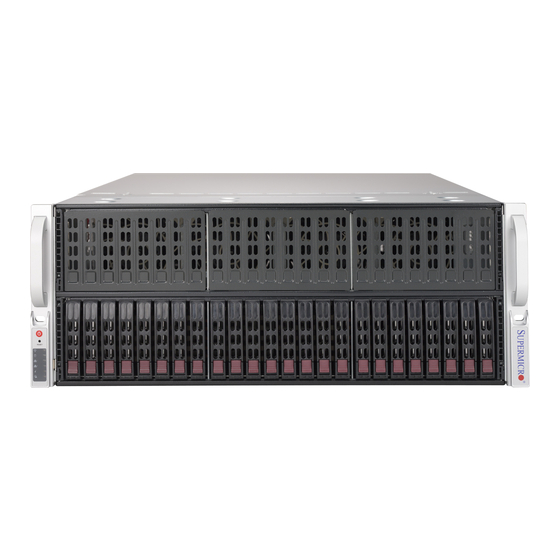
SuperServer 4029GP-TRT/TRT2/TRT3 User's Manual Front Features The SC418GTS-R4000BP2 is a 4U chassis See the illustration below for the features included on the front of the chassis. Figure 1-2. Chassis Front View Front Chassis Features Item Feature Description Hot-swap drive bays Drive bays for hot-swap 2.5"... -
Page 13: Rear Features
Chapter 1: Introduction Rear Features The illustration below shows the features included on the rear of the chassis. Figure 1-3. Chassis Rear View Rear Chassis Features Item Feature Description Power Supplies Two hot-swappable redundant power supplies are available for use. Rear I/O ports See Motherboard Layout below for details on the rear I/O ports. -
Page 14: Motherboard Layout
SuperServer 4029GP-TRT/TRT2/TRT3 User's Manual 1.5 Motherboard Layout Below is a layout of the X11DPG-O with jumper, connector and LED locations shown. See the table on the following page for descriptions. For detailed descriptions, pinout information and jumper settings, refer to Chapter 4. -
Page 15: Quick Reference Table
JNVI C1/ JNVI (an SMCI-proprietary NVMe add-on card and cable are required for each NVMe SMBus header. This feature is available for a Supermicro complete system only.) JPW19/20, JPW 21/22 SMCI-proprietary power supply units 19/20, 21/22 for system use JPWR1-8, JPWR9-16... - Page 16 SuperServer 4029GP-TRT/TRT2/TRT3 User's Manual Connector Description SATA5 SATA3.0 port with power-pin built-in w/support of SuperDOM (Device-On Module) S-SATA 0-3, 4-7 SATA3.0 connections supported by Intel SCU USB0 Type A internal USB 2.0 header (USB Port 0) USB1/2, 3/4 Backplane Universal Serial Bus (USB) 3.0 ports 1/2, 3/4...
- Page 17 Chapter 1: Introduction #M-2 #F-2 #M-1 #F-1 X11DPG-O-CPU #L-2 #E-2 #L-1 #E-1 #K-2 #D-2 #K-1 #D-1 #J-2 #C-2 #J-1 #C-1 10.4G #H-2 #B-2 VCCP0-(F) VCCP1 #H-1 #B-1 #G-2 DDR4 DDR4 #A-2 #G-1 #A-1 #3A #3C DMI3 PCI-E X16 G3 PCI-E X16 G3 PCI-E X16 G3 PCI-E X16 G3 PCI-E X8 G3...
-
Page 18: Chapter 2 Server Installation
SuperServer 4029GP-TRT/TRT2/TRT3 User's Manual Chapter 2 Server Installation 2.1 Overview This chapter provides advice and instructions for mounting your system in a server rack. If your system is not already fully integrated with processors, system memory etc., refer to Chapter 4 for details on installing those specific components. -
Page 19: Server Precautions
Chapter 2: Server Installation • In single rack installations, stabilizers should be attached to the rack. In multiple rack in- stallations, the racks should be coupled together. • Always make sure the rack is stable before extending a server or other component from the rack. -
Page 20: Circuit Overloading
SuperServer 4029GP-TRT/TRT2/TRT3 User's Manual Circuit Overloading Consideration should be given to the connection of the equipment to the power supply circuitry and the effect that any possible overloading of circuits might have on overcurrent protection and power supply wiring. Appropriate consideration of equipment nameplate ratings should be used when addressing this concern. -
Page 21: Procedure For Rack Mounting
Chapter 2: Server Installation 2.3 Procedure for Rack Mounting This section provides information on installing a 4U chassis into a rack unit with the rails provided. There are a variety of rack units on the market, so the assembly procedure may differ slightly. -
Page 22: Installing The Inner Rails On The Chassis
SuperServer 4029GP-TRT/TRT2/TRT3 User's Manual Warning: do not pick up the server with the front handles. They are designed to pull the system from a rack only. Figure 2-2. Installing the Inner Rails Note: The figure above is for illustrative purposes only. Always install servers at the bottom of the rack first. -
Page 23: Installing The Outer Rails Onto The Rack
Chapter 2: Server Installation Warning: Stability hazard. The rack stabilizing mechanism must be in place, or the rack must be bolted to the floor before you slide the unit out for servicing. Failure to stabilize the rack can cause the rack to tip over. Installing the Outer Rails onto the Rack Installing the Outer Rails 1. -
Page 24: Installing The Chassis Into A Rack
SuperServer 4029GP-TRT/TRT2/TRT3 User's Manual Figure 2-4. Installing the Chassis into a Rack Note: Figures are for illustrative purposes only. Always install servers into racks in the lower positions first. Installing the Chassis into a Rack Installing the Chassis into a Rack: 1. -
Page 25: Removing The Chassis From The Rack
Chapter 2: Server Installation Removing the Chassis from the Rack Caution! It is dangerous for a single person to off-load the heavy chassis from the rack without assistance. Be sure to have sufficient assistance supporting the chassis when removing it from the rack. -
Page 26: Chapter 3 Maintenance And Component Installation
SuperServer 4029GP-TRT/TRT2/TRT3 User's Manual Chapter 3 Maintenance and Component Installation This chapter provides instructions on installing and replacing main system components. To prevent compatibility issues, only use components that match the specifications and/or part numbers given. Installation or replacement of most components require that power first be removed from the system. - Page 27 Chapter 3: Maintenance and Component Installation Figure 3-1. Accessing the Inside of the System Caution: Except for short periods of time, do not operate the server without the cover in place. The chassis cover must be in place to allow proper airflow and prevent overheating.
-
Page 28: Processor And Heatsink Installation
Thermal grease is pre-applied on a new heatsink. No additional thermal grease is needed. • Refer to the Supermicro website for updates on processor support. • All graphics in this manual are for illustrations only. Your components may look different. -
Page 29: Overview Of The Processor Carrier Assembly
Chapter 3: Maintenance and Component Installation Overview of the Processor Carrier Assembly The processor carrier assembly contains the Intel Xeon Non-Fabric (Non-F) processor and a processor carrier. 1. Non-F Processor 2. Processor Carrier Overview of the CPU Socket The CPU socket is protected by a plastic protective cover. 1. -
Page 30: Overview Of The Processor Heatsink Module
SuperServer 4029GP-TRT/TRT2/TRT3 User's Manual Overview of the Processor Heatsink Module The Processor Heatsink Module (PHM) contains a heatsink, a processor carrier, and the Intel Xeon Non-Fabric (Non-F) processor. 1. Heatsink with Thermal Grease 2. Processor Carrier 3. Non-F Processor Processor Heatsink Module... -
Page 31: Creating The Non-F Model Processor Carrier Assembly
Chapter 3: Maintenance and Component Installation Creating the Non-F Model Processor Carrier Assembly To install a Non-F model processor into the processor carrier, follow the steps below: 1. Hold the processor with the LGA lands (gold contacts) facing up. Locate the small, gold triangle in the corner of the processor and the corresponding hollowed triangle on the processor carrier. -
Page 32: Assembling The Processor Heatsink Module
SuperServer 4029GP-TRT/TRT2/TRT3 User's Manual Assembling the Processor Heatsink Module After creating the processor carrier assembly for the Non-F model processor, mount it onto the heatsink to create the processor heatsink module (PHM): 1. Note the label on top of the heatsink, which marks the heatsink mounting holes as 1, 2, 3, and 4. -
Page 33: Preparing The Cpu Socket For Installation
Chapter 3: Maintenance and Component Installation Preparing the CPU Socket for Installation This motherboard comes with a plastic protective cover installed on the CPU socket. Remove it from the socket to install the Processor Heatsink Module (PHM). Gently pull up one corner of the plastic protective cover to remove it. -
Page 34: Installing The Processor Heatsink Module (Phm)
SuperServer 4029GP-TRT/TRT2/TRT3 User's Manual Installing the Processor Heatsink Module (PHM) 1. Once you have assembled the processor heatsink module (PHM) by following the instructions, you are ready to install the processor heatsink module (PHM) into the CPU socket on the motherboard. To install the PHM into the CPU socket, follow the instructions below. -
Page 35: Removing The Processor Heatsink Module (Phm) From The Motherboard
Chapter 3: Maintenance and Component Installation Removing the Processor Heatsink Module (PHM) from the Motherboard Before removing the processor heatsink module (PHM), unplug power cord from the power outlet. 1. Using a T30 Torx-bit screwdriver, turn the screws on the PHM counterclockwise to loosen them from the socket, starting with screw marked #4 (in the sequence of 4, 3, 2, 2. -
Page 36: Memory Installation
• Put the memory modules into the antistatic bags when not in use. • Check the Supermicro website for recommended memory modules Introduction to Intel® Optane DC Persistent Memory Intel® 82xx/62xx/52xx/42xx supports new DCPMM (Optane™ DC Persistent Memory Modules) technology. DCPMM offers data persistence with higher capacity at lower latencies than the existing memory modules and provides hyper-speed storage capability for high performance computing platforms with flexible configuration options. -
Page 37: Memory Installation Sequence
Chapter 3: Maintenance and Component Installation DDR4 Memory Support for 81xx/61xx/51xx/41xx/31xx Processors Speed (MT/s) Ranks DIMM Capacity (GB) One Slot Two Slots per Channel per Channel DIMM Type One DIMM One DIMM Two DIMMs DRAM Density Data per Channel per Channel per Channel Width 4 Gb... -
Page 38: General Memory Population Requirements
Populating memory slots with a pair of DIMM modules of the same type and size will result in interleaved memory, which will improve memory performance.Check the Supermicro website for possible updates to memory support. DIMM Population Guidelines for Optimal Performance For optimal memory performance, follow the instructions listed in the tables below when populating memory modules. - Page 39 Chapter 3: Maintenance and Component Installation Memory Population Table for the X11DP Motherboard w/24 DIMM Slots Onboard CPUs/DIMMs Memory Population Sequence 1 CPU & 1 DIMM CPU1: P1-DIMMA1 1 CPU & 2 DIMMs CPU1: P1-DIMMA1/P1-DIMMD1 1 CPU & 3 DIMMs CPU1: P1-DIMMC1/P1-DIMMB1/P1-DIMMA1 1 CPU &...
- Page 40 SuperServer 4029GP-TRT/TRT2/TRT3 User's Manual Symmetric Population within 1 CPU Socket Channel Modes DIMMF1 DIMMF2 DIMME1 DIMME2 DIMMD1 DIMMD2 DIMMA2 DIMMA1 DIMMB2 DIMMB1 DIMMC2 DIMMC1 Config. DRAM1 DCPMM DRAM1 DCPMM DRAM1 DCPMM DCPMM DRAM1 DCPMM DRAM1 DCPMM DRAM1 2-2-2 DRAM1 DCPMM...
- Page 41 Chapter 3: Maintenance and Component Installation Validation Matrix (DDR4 DIMMs Validated w/DCPMM) DIMM Capacity (GB) Ranks Per DIMM DIMM Type & Data Width DRAM Density (Stack) 1Rx4 16GB RDIMM 2Rx8 16GB 2Rx4 16GB 32GB LRDIMM 4Rx4 64GB LRDIMM 3DS 8Rx4 (4H) 128GB...
-
Page 42: Dimm Installation
SuperServer 4029GP-TRT/TRT2/TRT3 User's Manual DIMM Installation 1. Follow the instructions given in the memory population guidelines listed in the previous sections to install memory modules on your motherboard. For the system to work properly, please use memory modules of the same type and... -
Page 43: Pci Expansion Card Installation
Chapter 3: Maintenance and Component Installation PCI Expansion Card Installation The system includes a daughterboard for GPU/PCIe expansion capabilities. See Figure 3-2 for an example of the daughterboard in the system. See Figures 3-3 and 3-4 for topology for the daughterboards in 4029GP-TRT/TRT2/TRT3 systems. Installing Expansion Cards 1. - Page 44 SuperServer 4029GP-TRT/TRT2/TRT3 User's Manual Figure 3-3. X9DRG-O-PCIE-P Daughter Board for 4029GP-TRT System Figure 3-4. X10DRG-O-PCIE-P Daughter Board for 4029GP-TRT2 System...
- Page 45 Chapter 3: Maintenance and Component Installation Figure 3-4. X11DPG-O-PCIE-P Daughter Board for 4029GP-TRT3 System...
-
Page 46: Motherboard Battery
SuperServer 4029GP-TRT/TRT2/TRT3 User's Manual Motherboard Battery The motherboard uses non-volatile memory to retain system information when system power is removed. This memory is powered by a lithium battery residing on the motherboard. Replacing the Battery Begin by removing power from the system as described in section 3.1. -
Page 47: Chassis Components
Chapter 3: Maintenance and Component Installation 3.4 Chassis Components Hard Drives The SC418G supports a total of 24 hard disk drives, which are mounted in drive carriers and reside within the hard drive bays. These drives are hot-swappable and can be removed or replaced without powering down the chassis. - Page 48 Note: Refer to the following FTP site for RAID setup guidelines: <ftp://ftp.supermicro.com/ driver/SAS/LSI/LSI_SAS_EmbMRAID_SWUG.pdf> and Supermicro’s web site for additional information < http://www.supermicro.com/support/manuals/>. Note: Enterprise level hard disk drives are recommended for use in Supermicro chassis and servers. For information on recommended HDDs, visit the Supermicro website at http://www. supermicro.com/products/nfo/files/storage/SBB-HDDCompList.pdf...
-
Page 49: Hard Drive Carrier Indicators
Chapter 3: Maintenance and Component Installation Caution: Use caution when working around the hard drive backplane. Do not touch the backplane with any metal objects and make sure no ribbon cables touch the backplane or obstruct the holes, which aid in proper airflow. Caution: Regardless of how many hard drives are installed, all drive carriers must remain in the drive bays to maintain proper airflow. -
Page 50: Replacing Fans
SuperServer 4029GP-TRT/TRT2/TRT3 User's Manual Replacing Fans The chassis contains eight 9-cm system fans that provide cooling for the system. All fans are hot-swappable, so there is no need to power down the system when switching fans. Changing a System Fan 1. -
Page 51: Power Supply
The failed power module can be replaced without powering-down the system. Replace with the same model. Replacement modules can be ordered directly from Supermicro. An amber light on the power supply is illuminated when the power is switched off. An green light indicates that the power supply is operating. -
Page 52: Chapter 4 Motherboard Connections
SuperServer 4029GP-TRT/TRT2/TRT3 User's Manual Chapter 4 Motherboard Connections This section describes the connections on the motherboard and provides pinout definitions. Note that depending on how the system is configured, not all connections are required. The LEDs on the motherboard are also described here. A serverboard layout indicating component locations may be found in Chapter 1. -
Page 53: Front Control Panel
JF1 contains header pins for various buttons and indicators that are normally located on a control panel at the front of the chassis. These connectors are designed specifically for use with Supermicro chassis. See the figure below for the descriptions of the front control panel buttons and LED indicators. - Page 54 SuperServer 4029GP-TRT/TRT2/TRT3 User's Manual Reset Button The Reset Button connection is located on pins 3 and 4 of JF1. Attach it to a hardware reset switch on the computer case to reset the system. Refer to the table below for pin definitions.
- Page 55 Chapter 4: Motherboard Connections NIC1/NIC2 (LAN1/LAN2) The NIC (Network Interface Controller) LED connection for LAN port 1 is located on pins 11 and 12 of JF1, and LAN port 2 is on pins 9 and 10. Attach the NIC LED cables here to display network activity.
-
Page 56: Ports And Headers
SuperServer 4029GP-TRT/TRT2/TRT3 User's Manual 4.3 Ports and Headers Rear I/O Ports See the figure below for the locations and descriptions of the various I/O ports on the rear of the motherboard. Figure 4-2. Rear I/O Ports I/O Back Panel Port Descriptions... - Page 57 (Note: UID can also be triggered via IPMI on the motherboard. For more information, please refer to the IPMI User's Guide posted on our website at http://www.supermicro.com.) UID Switch Pin Definitions...
-
Page 58: Connectors
(JS1/JS2). The S-SATA headers, supported by Intel SCU, provide eight S-SATA connections (S-SATA 0-3, 4-7), while SATA5, supported by the Intel PCH, can be used with the Supermicro SuperDOM. SuperDOM, a yellow SATA DOM connector with a power pin built in, does not require a power cable and is backward-compatible with a regular SATA HDD or a third-party SATA DOM that requires external power cables for power supply. -
Page 59: Headers
Chapter 4: Motherboard Connections Headers Onboard Fan Headers There are ten onboard fan headers (FAN1-FAN10) located on the motherboard. FAN1-FAN8 are used for system cooling, whereas FAN9/FAN10 are used as Active CPU heatsink fans. All onboard fans are 4-pin fan headers, which are backward compatible with traditional 3-pin fans. - Page 60 SuperServer 4029GP-TRT/TRT2/TRT3 User's Manual Chassis Intrusion A Chassis Intrusion header is located at JL1 on the motherboard. Attach the appropriate cable from the chassis to inform you of a chassis intrusion when the chassis is opened. Refer to the table below for pin definitions.
-
Page 61: Host Fabric Interface (Hfi) Carrier Card Sideband Headers (Available When F Model Cpus Are Used)
C2), used for PCI-E SMBus clock and data connections, provide hot-plug support via dedicated SMBus interface. This feature is only available for a Supermicro complete system with an SMCI-proprietary NVMe add-on card and cable installed for each NVMe SMBus header supported. See the table below for pin definitions. -
Page 62: Jumpers
SuperServer 4029GP-TRT/TRT2/TRT3 User's Manual 4.4 Jumpers Explanation of Jumpers To modify the operation of the motherboard, jumpers are used to choose between optional settings. Jumpers create shorts between two pins to change the function associated with it. Pin 1 is identified with a square solder pad on the printed circuit board. See the motherboard layout page for jumper locations. - Page 63 Chapter 4: Motherboard Connections VGA Port Enable/Disable Jumper JPG1 is used to enable or disable the VGA port on the I/O back panel. Close pin 1 and pin 2 for VGA support. The default setting is Enabled. VGA Port Enable/Disable Jumper Settings Jumper Definition...
- Page 64 SuperServer 4029GP-TRT/TRT2/TRT3 User's Manual C Bus for VRM Jumpers JVRM1 and JVRM2 allow the VRM SMB Clock and Data to access the Baseboard Management Controller (BMC). See the tables below for jumper settings. JVRM1 (VRM SMB Clock to BMC/PCH) Jumper Settings...
-
Page 65: Led Indicators
Chapter 4: Motherboard Connections 4.5 LED Indicators LAN LEDs The LAN ports are located on the IO back panel of the motherboard. Each Ethernet LAN port has two LEDs. The yellow LED indicates activity. The Link LED, located on the left side of the LAN port, may be green, amber or off indicating the speed of the connection. - Page 66 SuperServer 4029GP-TRT/TRT2/TRT3 User's Manual BMC Heartbeat LED The BMC heartbeat LED is located at LED1. When this LED is blinking green, BMC is functioning normally. See the table below for the LED status. BMC Heartbeat LED Indicator LED Color Definition...
-
Page 67: Chapter 5 Software
USB/SATA DVD drive, or a USB flash drive, or the IPMI KVM console. 2. Retrieve the proper RST/RSTe driver. Go to the Supermicro web page for your motherboard and click on "Download the Latest Drivers and Utilities", select the proper driver, and copy it to a USB flash drive. - Page 68 SuperServer 4029GP-TRT/TRT2/TRT3 User's Manual 4. During Windows Setup, continue to the dialog where you select the drives on which to install Windows. If the disk you want to use is not listed, click on “Load driver” link at the bottom left corner.
-
Page 69: Driver Installation
The Supermicro website contains drivers and utilities for your system at https://www. supermicro.com/wftp/driver. Some of these must be installed, such as the chipset driver. After accessing the website, go into the CDR_Images (in the parent directory of the above link) and locate the ISO file for your motherboard. Download this file to to a USB flash drive or a DVD. -
Page 70: Superdoctor ® 5
5.3 SuperDoctor ® The Supermicro SuperDoctor 5 is a program that functions in a command-line or web-based interface for Windows and Linux operating systems. The program monitors such system health information as CPU temperature, system voltages, system power consumption, fan speed, and provides alerts via email or Simple Network Management Protocol (SNMP). -
Page 71: Ipmi
The X11DPG-O supports the Intelligent Platform Management Interface (IPMI). IPMI is used to provide remote access, monitoring and management. There are several BIOS settings that are related to IPMI. For general documentation and information on IPMI, please visit our website at: http://www.supermicro.com/products/nfo/IPMI.cfm. -
Page 72: Chapter 6 Uefi Bios
SuperServer 4029GP-TRT/TRT2/TRT3 User's Manual Chapter 6 UEFI BIOS 6.1 Introduction This chapter describes the UEFI Setup utility for the X11DPG-O motherboard(s). The BIOS is stored on a chip and can be easily upgraded using a flash program. Note: Due to periodic changes to the BIOS, some settings may have been added or deleted and might not yet be recorded in this manual. -
Page 73: Main Setup
Note: The time is in the 24-hour format. For example, 5:30 P.M. appears as 17:30:00. The date's default value is 01/01/2014 after RTC reset. Supermicro X11DPH-Tq BIOS Version This item displays the version of the BIOS ROM used in the system. - Page 74 SuperServer 4029GP-TRT/TRT2/TRT3 User's Manual Build Date This item displays the date when the version of the BIOS ROM used in the system was built. CPLD Version This item displays the version of the CPLD (Complex-Programmable Logical Device) used in the system.
-
Page 75: Advanced Setup Configurations
Chapter 6: UEFI BIOS 6.3 Advanced Setup Configurations Use the arrow keys to select the Advanced submenu and press <Enter> to access the submenu items. Warning: Take Caution when changing the Advanced settings. An incorrect value, an incorrect DRAM frequency, or an incorrect BIOS timing setting may cause the system to malfunction. When this occurs, restore the setting to the manufacture default setting. - Page 76 SuperServer 4029GP-TRT/TRT2/TRT3 User's Manual Option ROM Messages Use this feature to set the display mode for the Option ROM. Select Keep Current to use the current AddOn ROM display setting. Select Force BIOS to use the Option ROM display mode set by the system BIOS. The options are Force BIOS and Keep Current.
- Page 77 Chapter 6: UEFI BIOS CPU Configuration Warning: Setting the wrong values in the following sections may cause the system to malfunc- tion. Processor Configuration The following CPU information will be displayed: • Processor BSP Revision • Processor Socket •...
- Page 78 SuperServer 4029GP-TRT/TRT2/TRT3 User's Manual IED Trace Memory Use this feature to determine how the system should allocate memory for PSMI trace. The options are Disable, 4M, 8M, 16M, 32M, 64M, 128M, 256M, 512M, and 1G. Execute Disable Bit (Available if supported by the OS & the CPU)
- Page 79 Chapter 6: UEFI BIOS DCU IP Prefetcher If this feature is set to Enable, the IP prefetcher in the DCU (Data Cache Unit) will prefetch IP addresses to improve network connectivity and system performance. The options are Enable and Disable. LLC Prefetch If this feature is set to Enable, LLC (hardware cache) prefetching on all threads will be supported.
- Page 80 SuperServer 4029GP-TRT/TRT2/TRT3 User's Manual CPU P State Control (Available when "Power Technology" is set to Custom) SpeedStep (PStates) EIST (Enhanced Intel SpeedStep Technology) allows the system to automatically adjust processor voltage and core frequency in an effort to reduce power consumption and heat dissipation.
- Page 81 Chapter 6: UEFI BIOS Enhanced Halt State (C1E) Select Enable to enable "Enhanced Halt State" support, which will significantly reduce the CPU's power consumption by minimizing CPU's clock cycles and reduce voltage during a "Halt State." The options are Disable and Enable. Package C State Control (Available when "Power Technology"...
- Page 82 SuperServer 4029GP-TRT/TRT2/TRT3 User's Manual Degrade Precedence Use this feature to select the degrading precedence option for Ultra Path Interconnect connections. Select Topology Precedent to degrade UPI features if system options are in conflict. Select Feature Precedent to degrade UPI topology if system options are in conflict.
- Page 83 Chapter 6: UEFI BIOS LLC Dead Line Alloc Select Enable to opportunistically fill the deadlines in LLC. The options are Enable, Disable, and Auto. Isoc Mode Select Enable to enable Isochronous support to meet QoS (Quality of Service) requirements. This feature is especially important for Virtualization Technology. The options are Disable, Enable, and Auto.
- Page 84 SuperServer 4029GP-TRT/TRT2/TRT3 User's Manual 2X Refresh Select Enable for memory 2X refresh support to enhance memory performance. The options are Enable and Auto. Page Policy Use this feature to set the page policy for onboard memory support The options are Closed, Adaptive and Auto.
- Page 85 Chapter 6: UEFI BIOS Memory Rank Sparing Select Enable to support memory-rank sparing to optimize memory performance. The options are Enable and Disable. Note: This item will not be available when memory mirror mode is enabled. Correctable Error Threshold Use this item to enter the threshold value for correctable memory errors. The default setting is 10.
- Page 86 SuperServer 4029GP-TRT/TRT2/TRT3 User's Manual IIO Configuration EV DFX (Device Function On-Hide) Features When this feature is set to Enable, the EV_DFX Lock Bits that are located in a processor will always remain clear during electric tuning. The options are Disable and Enable.
- Page 87 Chapter 6: UEFI BIOS PCI-E Port Max (Maximum) Payload Size (Available for CPU 1 Configuration only) Select Auto for the system BIOS to automatically set the maximum payload value for a PCI-E device specified by to user to enhance system performance. The options are Auto, 128B, and 256B.
- Page 88 SuperServer 4029GP-TRT/TRT2/TRT3 User's Manual Posted Interrupt Select Enable to support VT_D Posted Interrupt which will allow external interrupts to be sent directly from a direct-assigned device to a client machine in non-root mode to improve virtualization efficiency by simplifying interrupt migration and lessening the need of physical interrupts.
- Page 89 Chapter 6: UEFI BIOS Port 60/64 Emulation Select Enabled for I/O port 60h/64h emulation support, which in turn, will provide complete legacy USB keyboard support for the operating systems that do not support legacy USB devices. The options are Enabled and Disabled. PCI-E PLL SSC Select Enable for PCH PCIe Spread Spectrum Clocking support, which will allow the BIOS to monitor and attempt to reduce the level of Electromagnetic Interference caused by the...
- Page 90 SuperServer 4029GP-TRT/TRT2/TRT3 User's Manual SATA HDD Unlock Select Enable to unlock SATA HDD password in the OS. The options are Enable and Disable. SATA RSTe Boot Info (Available when the item "Configure SATA as" is set to "RAID") Select Enable to enable full int13h support for devices connected to the SATA controller which will allow these SATA devices to be used as boot devices for system boot.
- Page 91 Chapter 6: UEFI BIOS PCH sSATA Configuration When this submenu is selected, AMI BIOS automatically detects the presence of the sSATA devices that are supported by the PCH sSATA controller and displays the following items: sSATA Controller This item enables or disables the onboard sSATA controller supported by the Intel SCU. The options are Enable and Disable.
- Page 92 SuperServer 4029GP-TRT/TRT2/TRT3 User's Manual sSATA Device Type Use this item to specify if the device installed on the sSATA port specified by the user should be connected to a Solid State drive or a Hard Disk Drive. The options are Hard Disk Drive and Solid State Drive.
- Page 93 Chapter 6: UEFI BIOS VGA Priority This feature selects the graphics device to be used as the primary video display for system boot. The options are Auto, Onboard and Offboard. CPU1 Slot 1 PCI-E 3.0 x8 OPROM/CPU2 Slot 2 PCI-E 3.0 x16 OPROM/CPU1 Slot 3 PCI-E 3.0 x8 OPROM/CPU2 Slot 4 PCI-E 3.0 x16 OPROM/CPU2 Slot 5 PCI-E 3.0 x16 OPROM/CPU1 Slot 6 PCI-E 3.0 x8 OPROM/CPU1 Slot 7 PCI-E 3.0 x8 OPROM/M.2-C1 3.0 x4 OPROM/M.2-C2 3.0 x4 OPROM...
- Page 94 SuperServer 4029GP-TRT/TRT2/TRT3 User's Manual Ipv4 HTTP Support Select Enabled to enable Ipv4 HTTP boot support. If this feature is disabled, it will not create the Ipv4 HTTP boot option. The options are Enabled and Disabled. Ipv6 PXE Support Select Enabled to enable Ipv6 PXE boot support. If this feature is disabled, it will not create the Ipv6 PXE boot option.
- Page 95 Chapter 6: UEFI BIOS Serial Port 2 Configuration Serial Port 2 Select Enabled to enable the onboard serial port specified by the user. The options are Enabled and Disabled. Device Settings This feature displays the base I/O port address and the Interrupt Request address of a serial port specified by the user.
- Page 96 SuperServer 4029GP-TRT/TRT2/TRT3 User's Manual Bits Per second Use this feature to set the transmission speed for a serial port used in Console Redirection. Make sure that the same speed is used in the host computer and the client computer. A lower transmission speed may be required for long and busy lines.
- Page 97 Chapter 6: UEFI BIOS Putty KeyPad This feature selects Function Keys and KeyPad settings for Putty, which is a terminal emulator designed for the Windows OS. The options are VT100, LINUX, XTERMR6, SCO, ESCN, and VT400. Redirection After BIOS Post Use this feature to enable or disable legacy Console Redirection after BIOS POST.
- Page 98 SuperServer 4029GP-TRT/TRT2/TRT3 User's Manual Parity A parity bit can be sent along with regular data bits to detect data transmission errors. Select Even if the parity bit is set to 0, and the number of 1's in data bits is even. Select Odd if the parity bit is set to 0, and the number of 1's in data bits is odd.
- Page 99 Chapter 6: UEFI BIOS Redirection After BIOS Post Use this feature to enable or disable legacy Console Redirection after BIOS POST (Power-On Self-Test). When this feature is set to Bootloader, legacy Console Redirection is disabled before booting the OS. When this feature is set to Always Enable, legacy Console Redirection remains enabled upon OS boot.
- Page 100 SuperServer 4029GP-TRT/TRT2/TRT3 User's Manual Flow Control Use this feature to set the flow control for Console Redirection to prevent data loss caused by buffer overflow. Send a "Stop" signal to stop data-sending when the receiving buffer is full. Send a "Start" signal to start data-sending when the receiving buffer is empty. The options are None, Hardware RTS/CTS, and Software Xon/Xoff.
- Page 101 Chapter 6: UEFI BIOS Trusted Computing (Available when a TPM device is detected and PTT Support under "Server ME Config" is not Enabled) When a TPM (Trusted-Platform Module) device is detected in your machine, the following information will display. •...
- Page 102 SuperServer 4029GP-TRT/TRT2/TRT3 User's Manual Pending Operation Use this feature to schedule a TPM-related operation to be performed by a security (TPM) device at the next system boot to enhance system data integrity. Your system will reboot to carry out a pending TPM operation. The options are None and TPM Clear.
- Page 103 Chapter 6: UEFI BIOS Note 2: For more information on TPM, please refer to the TPM manual at http://www. supermicro.com/manuals/other. iSCSi Configuration iSCSI Initiator Name This feature allows the user to enter the unique name of the iSCSI Initiator in IQN format.
-
Page 104: Event Logs
SuperServer 4029GP-TRT/TRT2/TRT3 User's Manual 6.4 Event Logs Use this feature to configure Event Log settings. Change SMBIOS Event Log Settings Enabling/Disabling Options SMBIOS Event Log Select Enabled to enable SMBIOS (System Management BIOS) Event Logging during system boot. The options are Enabled and Disabled. - Page 105 Chapter 6: UEFI BIOS SMBIOS Event Log Standard Settings Log System Boot Event Select Enabled to log system boot events. The options are Enabled and Disabled. MECI (Multiple Event Count Increment) Enter the increment value for the multiple event counter. Enter a number between 1 to 255. The default setting is 1.
-
Page 106: Ipmi
SuperServer 4029GP-TRT/TRT2/TRT3 User's Manual 6.5 IPMI Use this feature to configure Intelligent Platform Management Interface (IPMI) settings. When you select this submenu and press the <Enter> key, the following information will display: • BMC Firmware Revision: This feature indicates the IPMI firmware revision used in your system. - Page 107 Chapter 6: UEFI BIOS Erasing Settings Erase SEL Select Yes, On next reset to erase all system event logs upon next system reboot. Select Yes, On every reset to erase all system event logs upon each system reboot. Select No to keep all system event logs after each system reboot.
- Page 108 SuperServer 4029GP-TRT/TRT2/TRT3 User's Manual IPV6 Support Select Enabled for IPV6 support. The options are Enabled and Disabled. Configuration Address Source Use this feature to select the IP address source for this computer. If Static is selected, you will need to know the IP address of this computer and enter it to the system manually in the field.
-
Page 109: Security Settings
Chapter 6: UEFI BIOS 6.6 Security Settings This menu allows the user to configure the following security settings for the system. Administrator Password Use this feature to set the administrator password which is required to enter the BIOS setup utility. The length of the password should be from 3 characters to 20 characters long. User Password Use this feature to set the user password which is required to enter the BIOS setup utility. - Page 110 SuperServer 4029GP-TRT/TRT2/TRT3 User's Manual Secure Boot When you select this submenu and press the <Enter> key, the following items will display: • System Mode • Secure Boot • Vendor Keys Secure Boot If this feature is set to Enabled, Secure Boot will be activated when a Platform Key (PK) is entered.
- Page 111 Chapter 6: UEFI BIOS Platform Key (PK) This feature allows the user to enter and configure a set of values to be used as a platform firmware key for the system. This set of values also indicate the size, the keys numbers, and the key source of the Platform Key.
-
Page 112: Boot Settings
SuperServer 4029GP-TRT/TRT2/TRT3 User's Manual 6.7 Boot Settings Use this feature to configure Boot Settings: Boot Mode Select Use this feature to select the type of devices to be used for system boot. The options are Legacy, UEFI (Unified Extensible Firmware Interface), and Dual. - Page 113 Chapter 6: UEFI BIOS When the item above -"Boot Mode Select" is set to Legacy, the following items will be display for configuration: • Boot Option #1 - Boot Option #8 When the item above -"Boot Mode Select" is set to UEFI, the following items will be display for configuration: •...
- Page 114 SuperServer 4029GP-TRT/TRT2/TRT3 User's Manual Create After the driver option name and the file path are set, press <Enter> to enter to submenu and click OK to create the new boot option drive. Delete Driver Option Use this item to select a boot driver to delete from the boot priority list.
-
Page 115: Save & Exit
Chapter 6: UEFI BIOS 6.8 Save & Exit Select the Save & Exit tab from the BIOS setup screen to configure the settings below. Save Options Discard Changes and Exit Select this option to quit the BIOS setup without making any permanent changes to the system configuration and reboot the computer. - Page 116 SuperServer 4029GP-TRT/TRT2/TRT3 User's Manual Discard Changes Select this option and press <Enter> to discard all the changes and return to the AMI BIOS setup utility. Default Options Restore Optimized Defaults To set this feature, select Restore Defaults from the Exit menu and press <Enter> to load manufacturer default settings which are intended for maximum system performance but not for maximum stability.
-
Page 117: Appendix A Bios Error Codes
Appendix A: BIOS Error Codes Appendix A BIOS Error Codes A.1 BIOS Error Beep (POST) Codes During the POST (Power-On Self-Test) routines, which are performed each time the system is powered on, errors may occur. Non-fatal errors are those which, in most cases, allow the system to continue the boot-up process. - Page 118 When BIOS performs the Power On Self Test, it writes checkpoint codes to I/O port 0080h. If the computer cannot complete the boot process, a diagnostic card can be attached to the computer to read I/O port 0080h (Supermicro p/n AOC-LPC80-20). For information on AMI updates, please refer to http://www.ami.com/products/.
-
Page 119: Appendix B Standardized Warning Statements For Ac Systems
Supermicro's Technical Support department for assistance. Only certified technicians should attempt to install or configure components. Read this appendix in its entirety before installing or configuring components in the Supermicro chassis. These warnings may also be found on our website at http://www.supermicro.com/about/... - Page 120 Appendix B: Standardized Warning Statements Warnung WICHTIGE SICHERHEITSHINWEISE Dieses Warnsymbol bedeutet Gefahr. Sie befinden sich in einer Situation, die zu Verletzungen führen kann. Machen Sie sich vor der Arbeit mit Geräten mit den Gefahren elektrischer Schaltungen und den üblichen Verfahren zur Vorbeugung vor Unfällen vertraut. Suchen Sie mit der am Ende jeder Warnung angegebenen Anweisungsnummer nach der jeweiligen Übersetzung in den übersetzten Sicherheitshinweisen, die zusammen mit diesem Gerät ausgeliefert wurden.
- Page 121 SuperServer 4029GP-TRT/TRT2/TRT3 User's Manual . ٌ ا ك ً ف حالة و ٌ يك أى تتسبب ف اصابة جسذ ة ٌ هذا الزهز ع ٌ خطز !تحذ ز قبل أى تعول عىل أي هعذات،يك عىل علن بالوخاطز ال ا ٌجوة عي الذوائز...
- Page 122 Appendix B: Standardized Warning Statements Warnung Vor dem Anschließen des Systems an die Stromquelle die Installationsanweisungen lesen. ¡Advertencia! Lea las instrucciones de instalación antes de conectar el sistema a la red de alimentación. Attention Avant de brancher le système sur la source d'alimentation, consulter les directives d'installation. .יש...
- Page 123 SuperServer 4029GP-TRT/TRT2/TRT3 User's Manual Warnung Dieses Produkt ist darauf angewiesen, dass im Gebäude ein Kurzschluss- bzw. Überstromschutz installiert ist. Stellen Sie sicher, dass der Nennwert der Schutzvorrichtung nicht mehr als: 250 V, 20 A beträgt. ¡Advertencia! Este equipo utiliza el sistema de protección contra cortocircuitos (o sobrecorrientes) del edificio.
- Page 124 Appendix B: Standardized Warning Statements Power Disconnection Warning Warning! The system must be disconnected from all sources of power and the power cord removed from the power supply module(s) before accessing the chassis interior to install or remove system components. 電源切断の警告...
- Page 125 SuperServer 4029GP-TRT/TRT2/TRT3 User's Manual يجب فصم اننظاو من جميع مصادر انطاقت وإ ز انت سهك انكهرباء من وحدة امداد انطاقت قبم انىصىل إىن امنناطق انداخهيت نههيكم نتثبيج أو إ ز انت مكىناث الجهاز 경고! 시스템에 부품들을 장착하거나 제거하기 위해서는 섀시 내부에 접근하기 전에 반드시 전원...
- Page 126 Appendix B: Standardized Warning Statements Attention Il est vivement recommandé de confier l'installation, le remplacement et la maintenance de ces équipements à des personnels qualifiés et expérimentés. !אזהרה .צוות מוסמך בלבד רשאי להתקין, להחליף את הציוד או לתת שירות עבור הציוד واملدربيه...
- Page 127 SuperServer 4029GP-TRT/TRT2/TRT3 User's Manual Warnung Diese Einheit ist zur Installation in Bereichen mit beschränktem Zutritt vorgesehen. Der Zutritt zu derartigen Bereichen ist nur mit einem Spezialwerkzeug, Schloss und Schlüssel oder einer sonstigen Sicherheitsvorkehrung möglich. ¡Advertencia! Esta unidad ha sido diseñada para instalación en áreas de acceso restringido. Sólo puede obtenerse acceso a una de estas áreas mediante la utilización de una herramienta especial,...
- Page 128 Appendix B: Standardized Warning Statements Battery Handling Warning! There is the danger of explosion if the battery is replaced incorrectly. Replace the battery only with the same or equivalent type recommended by the manufacturer. Dispose of used batteries according to the manufacturer's instructions 電池の取り扱い...
- Page 129 SuperServer 4029GP-TRT/TRT2/TRT3 User's Manual هناك خطر من انفجار يف حالة اسحبذال البطارية بطريقة غري صحيحة فعليل اسحبذال البطارية فقط بنفس النىع أو ما يعادلها مام أوصث به الرشمة املصنعة جخلص من البطاريات املسحعملة وفقا لحعليامت الرشمة الصانعة 경고! 배터리가 올바르게 교체되지 않으면 폭발의 위험이 있습니다. 기존 배터리와 동일하거나 제...
- Page 130 Appendix B: Standardized Warning Statements ¡Advertencia! Puede que esta unidad tenga más de una conexión para fuentes de alimentación. Para cortar por completo el suministro de energía, deben desconectarse todas las conexiones. Attention Cette unité peut avoir plus d'une connexion d'alimentation. Pour supprimer toute tension et tout courant électrique de l'unité, toutes les connexions d'alimentation doivent être débranchées.
- Page 131 SuperServer 4029GP-TRT/TRT2/TRT3 User's Manual Backplane Voltage Warning! Hazardous voltage or energy is present on the backplane when the system is operating. Use caution when servicing. バックプレーンの電圧 システムの稼働中は危険な電圧または電力が、 バックプレーン上にかかっています。 修理する際には注意く ださい。 警告 当系统正在进行时,背板上有很危险的电压或能量,进行维修时务必小心。 警告 當系統正在進行時,背板上有危險的電壓或能量,進行維修時務必小心。 Warnung Wenn das System in Betrieb ist, treten auf der Rückwandplatine gefährliche Spannungen oder Energien auf.
- Page 132 Appendix B: Standardized Warning Statements هناك خطز مه التيار الكهزبايئ أوالطاقة املىجىدة عىل اللىحة عندما يكىن النظام يعمل كه حذ ر ا عند خدمة هذا الجهاس 경고! 시스템이 동작 중일 때 후면판 (Backplane)에는 위험한 전압이나 에너지가 발생 합니다. 서비스 작업 시 주의하십시오. Waarschuwing Een gevaarlijke spanning of energie is aanwezig op de backplane wanneer het systeem in gebruik is.
- Page 133 SuperServer 4029GP-TRT/TRT2/TRT3 User's Manual תיאום חוקי החשמל הארצי !אזהרה .התקנת הציוד חייבת להיות תואמת לחוקי החשמל המקומיים והארציים تركيب املعدات الكهربائية يجب أن ميتثل للقىاويه املحلية والىطىية املتعلقة بالكهرباء 경고! 현 지역 및 국가의 전기 규정에 따라 장비를 설치해야 합니다.
- Page 134 Appendix B: Standardized Warning Statements Attention La mise au rebut ou le recyclage de ce produit sont généralement soumis à des lois et/ou directives de respect de l'environnement. Renseignez-vous auprès de l'organisme compétent. סילוק המוצר !אזהרה .סילוק סופי של מוצר זה חייב להיות בהתאם להנחיות וחוקי המדינה التخلص...
- Page 135 SuperServer 4029GP-TRT/TRT2/TRT3 User's Manual Warnung Gefährlich Bewegende Teile. Von den bewegenden Lüfterblätter fern halten. Die Lüfter drehen sich u. U. noch, wenn die Lüfterbaugruppe aus dem Chassis genommen wird. Halten Sie Finger, Schraubendreher und andere Gegenstände von den Öffnungen des Lüftergehäuses entfernt.
- Page 136 Verbindungskabeln, Stromkabeln und/oder Adapater, die Ihre örtlichen Sicherheitsstandards einhalten. Der Gebrauch von anderen Kabeln und Adapter können Fehlfunktionen oder Feuer verursachen. Die Richtlinien untersagen das Nutzen von UL oder CAS zertifizierten Kabeln (mit UL/CSA gekennzeichnet), an Geräten oder Produkten die nicht mit Supermicro gekennzeichnet sind.
- Page 137 حجم املوصل والقابس السليم. استخدام أي كابالت ومحوالت أخرى قد يتسبب يف عطل أو حريق. يحظر قانون السالمة لألجهزة الكهربائية واملعدات استخدام الكابالت املعتمدة من قبلUL أوCSA ( والتي تحمل عالمةUL/CSA) مع أي معدات أخرى غري املنتجات املعنية واملحددة من قبلSupermicro.
- Page 138 사항을 준수하여 제공되거나 지정된 연결 혹은 구매 케이블, 전원 케이블 및 AC 어댑터를 사용하십시오. 다른 케이블이나 어댑터를 사용하면 오작동이나 화재가 발생할 수 있습니다. 전기 용품 안전법은 UL 또는 CSA 인증 케이블 (코드에 UL / CSA가 표시된 케이블)을 Supermicro 가 지정한 제품 이외의 전기 장치에 사용하는 것을 금지합니다. Stroomkabel en AC-Adapter...
-
Page 139: Appendix C System Specifications
Appendix C: System Specifications Appendix C System Specifications Processors Dual Intel® 81xx/61xx/51xx/41xx/31xx or 82xx/62xx/52xx/42xx/32xx series processors in an Socket P0-LGA3647 type socket Note: Please refer to the motherboard specifications pages on our website for updates to supported processors. Chipset Intel PCH C622 chipset BIOS 256 Mb SPI AMI BIOS®... - Page 140 SuperServer 4029GP-TRT/TRT2/TRT3 User's Manual Regulatory Compliance Electromagnetic Emissions: FCC Class A, EN 55032 Class A, EN 61000-3-2/3-3, CISPR 32 Class A Electromagnetic Immunity: EN 55024/CISPR 24, (EN 61000-4-2, EN 61000-4-3, EN 61000-4-4, EN 61000-4-5, EN 61000-4-6, EN 61000-4-8, EN 61000-4-11), CNS14336-1, CNS13438, GB4943.1-2011, GB9254-2008(Class A) and GB17625.1-2012...
-
Page 141: Appendix D Uefi Bios Recovery
Warning: Do not upgrade the BIOS unless your system has a BIOS-related issue. Flashing the wrong BIOS can cause irreparable damage to the system. In no event shall Supermicro be liable for direct, indirect, special, incidental, or consequential damages arising from a BIOS update. - Page 142 SuperServer 4029GP-TRT/TRT2/TRT3 User's Manual The file system supported by UEFI is FAT (including FAT12, FAT16, and FAT32) which is installed on a bootable or non-bootable USB-attached device. However, the BIOS might need several minutes to locate the SUPER.ROM file if the media size becomes too large due to the huge volumes of folders and files stored in the device.
- Page 143 Appendix D: UEFI BIOS Recovery Warning: Please stop pressing the <Ctrl> and <Home> keys immediately when you see the screen (or a similar screen) below; otherwise, it will trigger a system reboot. 4. After locating the new BIOS binary image, the system will enter the BIOS Recovery menu as shown below.
- Page 144 SuperServer 4029GP-TRT/TRT2/TRT3 User's Manual 5. When the screen as shown above displays, use the arrow keys to select the item "Proceed with flash update" and press the <Enter> key. You will see the BIOS recovery progress as shown in the screen below.
- Page 145 Appendix D: UEFI BIOS Recovery 8. Press <Del> continuously during system boot to enter the BIOS setup utility. From the top of the tool bar, click on Boot and press <Enter> to enter the submenu. From the submenu list, select Boot Option #1 as shown below. Then, boot Option #1 to [UEFI AP:UEFI: Built-in EFI Shell].
-
Page 146: Appendix E Traditional Chinese Version Of Safety Warnings
SuperServer 4029GP-TRT/TRT2/TRT3 User's Manual Appendix E Traditional Chinese Version of Safety Warnings 限用物質含有情況標示聲明書 Lorem ipsum Declaration of the Presence Condition of the Restricted Substances Marking 設備名稱:伺服器/ Server Equipment name 型號(型式):418G-X11 Type designation (Type) 系列型號 : 4029GP-TRT; 4029GP-TRT2 限用物質及其化學符號 Restricted substances and its chemical symbols 六價鉻... - Page 147 Appendix E: Traditional Chinese Version of Safety Warnings * 輸入額定: 100-140V~, 60-50Hz, 12-9.8A 180-240V~, 60-50Hz, 10-9.8A * 使用者不能任意拆除或替換內部配備 * 報驗義務人之姓名或名稱: 美超微電腦股份有限公司 * 報驗義務人之地址: 新北市中和區建一路 150 號 3 樓...
Need help?
Do you have a question about the SuperServer 4029GP-TRT and is the answer not in the manual?
Questions and answers