Table of Contents
Advertisement
HPE IoT Gateway GL20 (Formerly HPE
EL20 Intelligent Gateway) User Guide
Abstract
This document is for the person who installs, administers, and troubleshoots servers and
storage systems. Hewlett Packard Enterprise assumes you are qualified in the servicing of
computer equipment and trained in recognizing hazards in products with hazardous energy
levels.
Part Number: 863926-004
Published: August 2017
Edition: 4
Advertisement
Table of Contents

Subscribe to Our Youtube Channel
Related Manuals for HPE Edgeline EL20


Summary of Contents for HPE Edgeline EL20
- Page 1 HPE IoT Gateway GL20 (Formerly HPE EL20 Intelligent Gateway) User Guide Abstract This document is for the person who installs, administers, and troubleshoots servers and storage systems. Hewlett Packard Enterprise assumes you are qualified in the servicing of computer equipment and trained in recognizing hazards in products with hazardous energy levels.
- Page 2 ™ NVIDIA is a trademark of NVIDIA Corporation in the U.S. and other countries. In mid 2017, Hewlett Packard Enterprise decided to re-brand the HPE EL20 Intelligent Gateway to the following: HPE IoT Gateway GL20 Some documentation and, labeling, or both might reference the following while HPE evaluates the re- brand of the HPE IoT Gateway product line: •...
-
Page 3: Table Of Contents
Contents Component identification...............6 Front panel components....................... 6 Front panel LEDs and buttons...................... 6 Rear panel components........................7 Expansion board components...................... 8 Antenna connector locations......................8 Digital I/O connector pin assignments..................9 Operations..................... 10 Install the power supply......................10 Power up the gateway........................ 10 Power down the gateway......................10 Install the antennas........................10 Install the WiFi or LTE antenna.................. - Page 4 Setting up the system BIOS..................... 35 BIOS menu components..................35 Navigating and modifying menu options............... 35 Main tab..........................36 Setting the System Date and System Time............36 Advanced tab........................36 PCI Subsystem Settings..................37 ACPI Settings......................38 S5 RTC Wake Settings..................38 CPU Configuration....................38 SATA Configuration....................
- Page 5 Websites....................53 Support and other resources...............54 Accessing Hewlett Packard Enterprise Support................. 54 Accessing updates........................54 Customer self repair........................55 Remote support.......................... 55 Acronyms and abbreviations...............56 Documentation feedback..............58 Contents...
-
Page 6: Component Identification
Component identification Front panel components LAN1 LAN2 HDMI Optional I/O 1 Optional I/O 2 Item Description USB 2.0 connectors (2) HDMI connector Drive bay VGA connector LAN connectors (2) Optional I/O serial connectors (RS-232 or RS-422/485) (2) USB 3.0 connectors (2) Front panel LEDs and buttons LAN1 LAN2... -
Page 7: Rear Panel Components
Item Description Status Reset button Press to reset the system Drive LED • Solid or flashing white = Drive active • Off = Drive not active Power LED • Solid green = System on • Off = System off Power On/Off button •... -
Page 8: Expansion Board Components
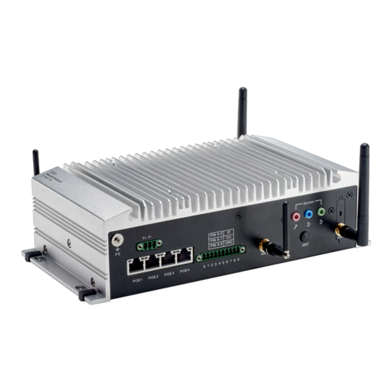
Expansion board components Item Description SIM card holders 3G module slots WiFi/WLAN module slots Antenna connector locations LAN1 LAN2 HDMI Optional I/O 1 Optional I/O 2 System PIN 0-5 PIN 6-7 PIN 8-9 1 2 3 3 4 5 6 7 8 9 POE1 POE2 POE3 POE4 Item... -
Page 9: Digital I/O Connector Pin Assignments
Digital I/O connector pin assignments 0 1 2 3 4 5 6 7 8 9 DO GND Assignment 0 to 5 Digital input 6 and 7 Digital output 8 and 9 Ground Digital I/O connector pin assignments... -
Page 10: Operations
Operations Install the power supply Procedure 1. Connect the power cord to the power connector at the rear of the gateway. 2. Power up the gateway. Power up the gateway If the gateway is connected to a power source, it powers up automatically. It needs to be powered up only after a manual shutdown. -
Page 11: Install The Wifi And Lte Combo Antennas
5. Mount the gateway on page 11. 6. Power up the gateway on page 10. Install the WiFi and LTE combo antennas You can connect WiFi antenna cables only, LTE antenna cables only, or the WiFi and LTE antenna cables together. -
Page 12: Dismount The Gateway
Dismount the gateway Procedure 1. Remove the four Torx head screws securing the wall-mount bracket to the wall. 2. Remove the four Torx head screws securing the wall-mount bracket to the gateway, and then remove the brackets. 3. Remove the wall-mount bracket from the gateway. Dismount the gateway... -
Page 13: Remove The Bottom Access Panel
Remove the bottom access panel Using a T-10 Torx head screwdriver, remove the six Torx head screws securing the access panel to the bottom of the gateway. Remove the bottom access panel... -
Page 14: Remove The Drive Tray
Remove the drive tray Procedure 1. Locate the drive tray on the side of the gateway. 2. Loosen the two thumbscrews securing the drive tray to the gateway, and then remove the drive tray. Remove the drive tray... -
Page 15: Setup
Hardware exchange offers a reliable and fast parts exchange service for eligible Hewlett Packard Enterprise products. Specifically targeted at products that can easily be shipped and on which you can easily restore data from backup files, HPE Foundation Care Next Business Day Exchange is a cost- efficient and convenient alternative to onsite support. -
Page 16: Power Requirements
For gateway-specific information, see "Hardware options installation." Installing the operating system The HPE IoT Gateway GL20s are standard, Intel-based PC server systems. However, the gateway does not include a CD or DVD-ROM device for installing the OS. To install a supported operating system in the gateway, you can use one of the following methods: •... - Page 17 Insert a USB drive into the workstation. The RUFUS utility will automatically detect the USB drive and display the drive details. Setup...
- Page 18 Select ISO image from the Create a bootable disk using drop-down. Click the disk icon, and select the ISO image of the required OS. Confirm that Standard Windows installation is selected. Setup...
-
Page 19: Install Os Using The Imaged Usb
Click the Start button to begin the USB key imaging process. It will take approximately 15 minutes for the imaging process to complete. Click the Close button to close the RUFUS utility. 10. Safely remove the imaged USB key from the workstation. Install OS using the imaged USB Prerequisites The gateway should be powered off before starting this procedure. - Page 20 Select Boot Option #1 under Boot Option Priorities. A menu for selecting the Boot Option #1 is displayed. Select the USB key as Boot Option #1. Setup...
- Page 21 Press the Escape key. Navigate to the Save & Exit tab. 10. Select Boot Override. 11. Select the USB key option. Setup...
-
Page 22: Installing Os Using Local Media
12. Press Enter. 13. Follow the OS installation prompts to complete the OS installation on the device. Wait for the OS installation to complete. 14. Remove the USB key from the gateway. The OS installation from the USB key is complete. The gateway boots from the new HDD at reboot. Installing OS using local media You can use local media such as a USB CD, DVD, or disk drive with installation media to install the OS. -
Page 23: Hardware Options Installation
Hardware options installation Installing the 3G/LTE module Procedure 1. Power down the gateway on page 10. 2. Dismount the gateway on page 12. CAUTION: DO NOT remove the top access panel under any circumstance. Removing the top access panel can harm the heatsink or void the warranty to the equipment. 3. -
Page 24: Installing The Half-Length Wifi/Wlan Module
6. Install the bottom access panel. 7. Mount the gateway on page 11. 8. Power up the gateway on page 10. Installing the half-length WiFi/WLAN module You will need a half-length WiFi module adapter provided with the WiFi option kit to install this option. Procedure Power down the gateway on page 10. - Page 25 Insert the WiFi module connector into the full-length WiFi module slot. Using a T-10 Torx screwdriver, install the half-length WiFi module and adapter assembly with the two screws. Connect the two WLAN antenna cables to the antenna connectors on the half-length WiFi module. Hardware options installation...
-
Page 26: Installing The Full-Length Wifi/Wlan Module
Install the bottom access panel. 10. Mount the gateway on page 11. 11. Power up the gateway on page 10. Installing the full-length WiFi/WLAN module Procedure 1. Power down the gateway on page 10. 2. Dismount the gateway on page 12. CAUTION: DO NOT remove the top access panel under any circumstance. - Page 27 6. Connect the two WLAN antenna cables to the antenna connectors on the full-length WiFi module. 7. Install the bottom access panel. 8. Mount the gateway on page 11. 9. Power up the gateway on page 10. Hardware options installation...
-
Page 28: Software And Configuration Utilities
Software and configuration utilities Product QuickSpecs For more information about product features, specifications, options, configurations, and compatibility, see the product QuickSpecs on the Hewlett Packard Enterprise website (http://www.hpe.com/info/qs). Supported operating systems and drivers matrix Operating system support For more information on Hewlett Packard Enterprise Certified and Supported systems for the operating systems available for your system, see the Hewlett Packard Enterprise OS support website: http://www.hpe.com/info/ossupport... - Page 29 Identify the current Management Engine version by using Advanced —> PCH-FW Configuration. The old Management Engine Firmware version is 9.5.13.1706 and the updated version is 9.5.61.3012. Software and configuration utilities...
- Page 30 Alternatively, press the Ctrl+P keys while the device boots to identify the ME FW version. Modify the following settings in the BIOS: a. Set ME FW Image Re-Flash to [Enabled] by using Advanced—>PCH-FW Configuration— >Firmware Update Configuration. b. Set UEFI: Built-in EFI Shell as Boot Option #1. Software and configuration utilities...
- Page 31 Select Save Changes and Exit. The settings changes made so far will take effect only if you save and exit. The system will now boot to the Shell. The following is a sample screen: If your screen looks different from the sample screen provided, reset the UEFI: Built-in EFI Shell to Boot Option #1.
- Page 32 The following is a sample screen with fs1 as the USB drive. 11. Initiate the BIOS update: a. To select the USB drive, enter the fs1: command. b. To ensure that both the utility and bin files are visible, enter the dir command. c.
- Page 33 After the update, one of the following screens appear: • An error screen showing that the BIOS does not support ME Entire Firmware update. The following is a sample screen: Software and configuration utilities...
-
Page 34: Using The System Bios To Configure Gateway And Troubleshoot Issues
To fix this error, repeat the steps from accessing the BIOS to save changes and exit, and then run the update again. • A screen showing that the BIOS update was successful. The following is a sample screen: 12. Power down the gateway on page 10 for the changes to take effect. All BIOS options are restored to the default values and the Management Engine password is set back to the default password. -
Page 35: Accessing The System Bios
For more information, see "Setting up the system BIOS." Accessing the system BIOS Procedure 1. Connect KVM to the gateway. 2. Power up the gateway. 3. Press the Delete key or the F2 key. The BIOS Main tab is displayed. Setting up the system BIOS BIOS menu components The BIOS menu has the following frames:... -
Page 36: Main Tab
Main tab Setting the System Date and System Time Procedure 1. Access the system BIOS Main tab. 2. Press the up and down arrow keys to navigate to the sub-menu options on the left frame. 3. When you reach a sub-menu option to modify, press the Enter key. 4. -
Page 37: Pci Subsystem Settings
• Intel(R) Rapid Start Technology • PCH-FW Configuration • AMT Configuration (not active) • USB Configuration • Embedded Controller Configuration • IT8768 Super IO Configuration • Serial Port Console Redirection • Network Stack • Intel(R) Ethernet Connection PCI Subsystem Settings The PCI Bus driver version and common settings are displayed, including: •... -
Page 38: Acpi Settings
◦ Extended Synch—Enables user to allow the generation of extended synchronization patterns. ◦ Link Training Retry—Enables user to define the number of retry attempts the software will make to retrain the link if previous training attempt was unsuccessful ◦ Link Training Timeout (uS)—Enables user to define the number of microseconds the software will wait before polling 'Link Training' bit in Link Status register. -
Page 39: Intel(R) Rapid Start Technology
• Software Preserve • Port #—Enables or disables the SATA port • Hot Plug—Enables or disables the hot plug • External SATA—Enables or disables the external SATA • SATA Device type—Enables user to select the mode of SATA device type Intel(R) Rapid Start Technology Intel(R) Rapid Start Technology—Enables or disables Rapid Start Technology, if supported PCH-FW Configuration... -
Page 40: Network Stack
• Console Redirection—Enables or disables console redirection for Microsoft Windows EMS • Console Redirection Settings—Enables user to set configuration console redirection detail settings Network Stack Network Stack—Enables or disables the UEFI network stack Intel (R) Ethernet Connection The Port Configuration Menu information is displayed, including: •... -
Page 41: System Agent (Sa) Configuration
◦ PCIe-USB Glitch W/A—Enables or disables PCIe-USB Glitch workaround for bad USB devices connected behind the PCIE/PEG Port. ◦ PCI Root Port Function Swapping—Enables or disables PCI Express root port function swapping ◦ Subtractive Decode—Enables or disables subtractive decode ◦ PCI Express Root Port 1/2/3/6—Enables user to configure PCI express root port 1/2/3/6 setting •... -
Page 42: Csm Parameters
CSM parameters • Launch CSM—Enables or disables CSM launch • Boot option filter—Enables user to select which devices the system can boot to • Launch PXE OpROM policy—Enables user to control the execution of UEFI and legacy PXE Option • Launch Storage OpROM policy—Enables user to control the execution of UEFI and legacy Storage Option ROM •... -
Page 43: Secure Boot
Secure Boot The system mode and secure boot configuration is displayed, including the following: • Secure Boot—Enables or disables Secure Boot • Secure Boot Mode—Secure Boot mode selector. Enables user to change the image execution policy and manage secure boot keys •... - Page 44 • Discard Changes—Enables user to discard changes made so far to any of the options • Restore Defaults—Enables user to restore/load default values for all the options • Save as User Defaults—Enables user to save the changes made so far as user defaults •...
-
Page 45: Troubleshooting
Troubleshooting Troubleshooting resources The HPE IoT Gateway GL20 (Formerly HPE EL20 Intelligent Gateway) Maintenance and Service Guide includes additional troubleshooting resources, and is available on the Hewlett Packard Enterprise website (http://www.hpe.com/info/edgeline-docs). Troubleshooting... -
Page 46: Battery
Battery Battery specifications Feature Specification Type CR2032 RTC batteries with a rating of 210 mAh Power Battery RTC circuitry draws 2uA when in use (system off) Maximum Battery 210 mAh/2 uAh = 10,5000 hours Life Cycle Maximum Battery 105000 hours/(365 x 24) = 11.98 years Life Cycle under (Battery in Storage Mode - System Powered Off all day, RTC battery is in use) Storage Mode... -
Page 47: Warranty And Regulatory Information
To view the warranty for your product or to view the Safety and Compliance Information for Server, Storage, Power, Networking, and Rack Products reference document, go to the Enterprise Safety and Compliance website: www.hpe.com/support/Safety-Compliance-EnterpriseProducts Additional warranty information HPE ProLiant and x86 Servers and Options www.hpe.com/support/ProLiantServers-Warranties HPE Enterprise Servers www.hpe.com/support/EnterpriseServers-Warranties HPE Storage Products www.hpe.com/support/Storage-Warranties... -
Page 48: Turkey Rohs Material Content Declaration
Manufacturer information: • Hewlett Packard Enterprise Company, 3000 Hanover Street, Palo Alto, CA 94304 U.S. Local representative information Russian: • Russia: • Belarus: • Kazakhstan: Local representative information Kazakh: • Russia: • Belarus: • Kazakhstan: Manufacturing date: The manufacturing date is defined by the serial number. CCSYWWZZZZ (serial number format for this product) Valid date formats include: •... -
Page 49: Ukraine Rohs Material Content Declaration
Ukraine RoHS material content declaration Japanese certification mark for 3G module Federal Communications Commission notice for Class A equipment This device complies with part 15 of the FCC Rules. Operation is subject to the following conditions: • This device may not cause harmful interference. •... - Page 50 Hereby, Hewlett Packard Enterprise declares that the radio equipment type used in the gateway is in compliance with Directive 2014/53/EU. The full text of the EU declaration of conformity is available at the following internet address: www.address.com/DoC.pdf The European Union WEEE Directive Page is available at: http://h20564.www2.hpe.com/portal/site/ hpesc/public/kb/docDisplay/?docId=c03471072. Warranty and regulatory information...
-
Page 51: Specifications
Specifications Product QuickSpecs For more information about product features, specifications, options, configurations, and compatibility, see the product QuickSpecs on the Hewlett Packard Enterprise website (http://www.hpe.com/info/qs). Environmental specifications Specification Value Temperature range — Operating -20°C to 60°C (-4°F to 140°F) with 0.7 m/s air flow with extended temperature peripherals 0°C to 45°C (32°F to 113°F) with 0.7 m/s air flow... -
Page 52: Power Consumption Specifications
Rated input current ~12.5 A (@ 12 VDC) Power supply output Rated output voltage 19.0 V Rated output current 7.89 A Power consumption specifications Specification Value Typical 70 W with full load on PoE Maximum 35 W The four-port PoE power budget is 30 W in total. Each PoE port supports up to <15 W at 802.3af Class 3. Power consumption specifications... -
Page 53: Websites
Websites General websites Hewlett Packard Enterprise Information Library www.hpe.com/info/EIL Single Point of Connectivity Knowledge (SPOCK) Storage compatibility matrix www.hpe.com/storage/spock Storage white papers and analyst reports www.hpe.com/storage/whitepapers For additional websites, see Support and other resources. Websites... -
Page 54: Support And Other Resources
Hewlett Packard Enterprise Support Center More Information on Access to Support Materials page: www.hpe.com/support/AccessToSupportMaterials IMPORTANT: Access to some updates might require product entitlement when accessed through the Hewlett Packard Enterprise Support Center. You must have an HPE Passport set up with relevant entitlements. Support and other resources... -
Page 55: Customer Self Repair
Remote support and Proactive Care information HPE Get Connected www.hpe.com/services/getconnected HPE Proactive Care services www.hpe.com/services/proactivecare HPE Proactive Care service: Supported products list www.hpe.com/services/proactivecaresupportedproducts HPE Proactive Care advanced service: Supported products list www.hpe.com/services/proactivecareadvancedsupportedproducts Proactive Care customer information Proactive Care central www.hpe.com/services/proactivecarecentral Proactive Care service activation www.hpe.com/services/proactivecarecentralgetstarted... -
Page 56: Acronyms And Abbreviations
Acronyms and abbreviations ACPI Advanced Configuration and Power Interface Advanced Encryption Standard Active Management Technology ASPM active state power management Azalia Intel high-definition audio BIOS Boot Specification CPUID CPU identification Compatibility Support Module cTDP configurable Thermal Design Power Desktop Management Interface DVMT dynamic video memory technology EHCI... - Page 57 Load Current Monitor Link Power Management long-term evolution Management Engine Platform Controller Hub peripheral component interconnect PCI Express Peripheral Component Interconnect Express PCIe Peripheral Component Interconnect Express Power over Ethernet Push-to-Talk preboot execution environment real-time clock Thermal Design Power UEFI Unified Extensible Firmware Interface VT-d Intel Virtualization Technology for Directed I/O...
-
Page 58: Documentation Feedback
Documentation Feedback (docsfeedback@hpe.com). When submitting your feedback, include the document title, part number, edition, and publication date located on the front cover of the document. For online help content, include the product name, product version, help edition, and publication date located on the legal notices page.
Need help?
Do you have a question about the Edgeline EL20 and is the answer not in the manual?
Questions and answers