Table of Contents
Advertisement
Quick Links
See also:
User Manual
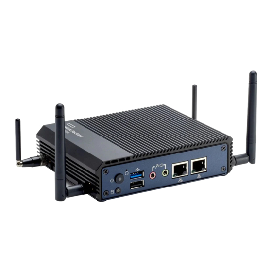
HPE Edgeline EL10 Intelligent Gateway
Maintenance and Service Guide
Abstract
This guide describes identification and maintenance procedures, diagnostic tools,
specifications, and requirements for hardware components and software. This guide is for an
experienced service technician. Hewlett Packard Enterprise assumes you are qualified in the
servicing of computer equipment, trained in recognizing hazards in products, and are familiar
with weight and stability precautions.
Part Number: 853646-003
Published: April 2017
Edition: 3
Advertisement
Table of Contents

Related Manuals for HPE EDGELINE EL10


Summary of Contents for HPE EDGELINE EL10
- Page 1 HPE Edgeline EL10 Intelligent Gateway Maintenance and Service Guide Abstract This guide describes identification and maintenance procedures, diagnostic tools, specifications, and requirements for hardware components and software. This guide is for an experienced service technician. Hewlett Packard Enterprise assumes you are qualified in the servicing of computer equipment, trained in recognizing hazards in products, and are familiar with weight and stability precautions.
- Page 2 © 2016, 2017 Hewlett Packard Enterprise Development LP Notices The information contained herein is subject to change without notice. The only warranties for Hewlett Packard Enterprise products and services are set forth in the express warranty statements accompanying such products and services. Nothing herein should be construed as constituting an additional warranty. Hewlett Packard Enterprise shall not be liable for technical or editorial errors or omissions contained herein.
-
Page 3: Table Of Contents
Contents Illustrated parts catalog................5 System components........................5 EL10 Intelligent Gateway spare part.................. 6 3G module/antenna spare parts ..................6 WiFi module/antenna spare parts ..................6 Drive spare part........................6 Power supply spare part....................6 Customer self repair................7 Removal and replacement procedures..........16 Required tools..........................16 Safety considerations........................16 Preventing electrostatic discharge................... - Page 4 Supported operating systems and drivers matrix................33 System BIOS..........................33 Using the system BIOS to configure system and troubleshoot issues ......33 Accessing the system BIOS.....................33 Setting up the system BIOS..................... 33 BIOS menu components..................33 Navigating and modifying menu options............... 34 Main tab............................
-
Page 5: Illustrated Parts Catalog
Illustrated parts catalog System components Hewlett Packard Enterprise continually improves and changes product parts. For complete and current supported parts information, see the Hewlett Packard Enterprise PartSurfer website (http:// www.hpe.com/info/partssurfer). Item Description EL10 Intelligent Gateway (4 GB RAM) spare part... -
Page 6: El10 Intelligent Gateway Spare Part
EL10 Intelligent Gateway spare part Customer self repair: Mandatory Description Spare part number EL10 Intelligent Gateway (4 GB RAM) 847063-001 3G module/antenna spare parts Customer self repair: Mandatory Description Spare part number 3G uPCIe Wide-Temp module Kit (includes 3G 847057-001 antenna) 3G antenna GSM 850/900/1800/1900/2100 MHz 871309-001... -
Page 7: Customer Self Repair
Customer self repair Hewlett Packard Enterprise products are designed with many Customer Self Repair (CSR) parts to minimize repair time and allow for greater flexibility in performing defective parts replacement. If during the diagnosis period Hewlett Packard Enterprise (or Hewlett Packard Enterprise service providers or service partners) identifies that the repair can be accomplished by the use of a CSR part, Hewlett Packard Enterprise will ship that part directly to you for replacement. - Page 8 demandez à Hewlett Packard Enterprise de remplacer ces pièces, l'intervention peut ou non vous être facturée, selon le type de garantie applicable à votre produit. REMARQUE: Certaines pièces Hewlett Packard Enterprise ne sont pas conçues pour permettre au client d'effectuer lui-même la réparation. Pour que la garantie puisse s'appliquer, Hewlett Packard Enterprise exige que le remplacement de la pièce soit effectué...
- Page 9 Hewlett Packard Enterprise entro un determinato periodo di tempo, generalmente cinque (5) giorni lavorativi. Il componente difettoso deve essere restituito con la documentazione associata nell'imballo di spedizione fornito. La mancata restituzione del componente può comportare la fatturazione del ricambio da parte di Hewlett Packard Enterprise. Nel caso di riparazione da parte del cliente, Hewlett Packard Enterprise sostiene tutte le spese di spedizione e resa e sceglie il corriere/vettore da utilizzare.
- Page 10 Parts-only Warranty Service (Garantieservice ausschließlich für Teile) Ihre Hewlett Packard Enterprise Garantie umfasst möglicherweise einen Parts-only Warranty Service (Garantieservice ausschließlich für Teile). Gemäß den Bestimmungen des Parts-only Warranty Service stellt Hewlett Packard Enterprise Ersatzteile kostenlos zur Verfügung. Für den Parts-only Warranty Service ist das CSR-Verfahren zwingend vorgegeben. Wenn Sie den Austausch dieser Teile von Hewlett Packard Enterprise vornehmen lassen, werden Ihnen die Anfahrt- und Arbeitskosten für diesen Service berechnet.
- Page 11 Customer Self Repair Veel onderdelen in Hewlett Packard Enterprise producten zijn door de klant zelf te repareren, waardoor de reparatieduur tot een minimum beperkt kan blijven en de flexibiliteit in het vervangen van defecte onderdelen groter is. Deze onderdelen worden CSR-onderdelen (Customer Self Repair) genoemd. Als Hewlett Packard Enterprise (of een Hewlett Packard Enterprise Service Partner) bij de diagnose vaststelt dat de reparatie kan worden uitgevoerd met een CSR-onderdeel, verzendt Hewlett Packard Enterprise dat onderdeel rechtstreeks naar u, zodat u het defecte onderdeel daarmee kunt vervangen.
- Page 12 • Obrigatória—Peças cujo reparo feito pelo cliente é obrigatório. Se desejar que a Hewlett Packard Enterprise substitua essas peças, serão cobradas as despesas de transporte e mão-de-obra do serviço. • Opcional—Peças cujo reparo feito pelo cliente é opcional. Essas peças também são projetadas para o reparo feito pelo cliente.
- Page 13 Customer self repair...
- Page 14 Customer self repair...
- Page 15 Customer self repair...
-
Page 16: Removal And Replacement Procedures
Removal and replacement procedures Required tools You need the following items for some procedures: • T-10 Torx screwdriver • M3.5 (3.5 mm) flathead screwdriver • M3 (3 mm) Phillips screwdriver Safety considerations Before performing service procedures, review all the safety information. Preventing electrostatic discharge To prevent damaging the system, be aware of the precautions you must follow when setting up the system or handling parts. -
Page 17: System Warnings And Cautions
This symbol indicates the presence of a hot surface or hot component. If this surface is contacted, the potential for injury exists. WARNING: To reduce the risk of injury from a hot component, allow the surface to cool before touching. This symbol indicates that the component exceeds the recommended weight for one individual to handle safely. -
Page 18: Powering Down The Gateway
If you must dismount the gateway or remove a non-hot-plug component from the gateway, then you must power down the gateway. 2. Dismount the gateway. If the environment, cabling configuration, or the gateway location creates unstable conditions, then dismount the gateway and place it on a stable surface. 3. -
Page 19: Dismounting A Rack-Mount Gateway
To replace the component, reverse the removal procedure. Dismounting a rack-mount gateway Procedure 1. Slide the rail mounts off the wall-mount brackets. 2. Remove the four screws securing the wall-mount brackets to the gateway, and then remove the brackets. To replace the component, reverse the removal procedure. Dismounting a VESA-mount gateway Procedure 1. -
Page 20: Removing The Bottom Access Panel
To replace the component, reverse the removal procedure. Removing the bottom access panel Procedure 1. Using a Torx head screwdriver, remove the four T-10 Torx head screws securing the access panel to the bottom of the gateway. 2. Lift the access panel up, and then set it to the side. The jumper cables connecting the drive are still attached. -
Page 21: Removing And Replacing A Drive
Removing and replacing a drive Procedure 1. Power down the gateway. 2. Dismount the gateway. CAUTION: DO NOT remove the top access panel under any circumstance. Removing the top access panel can harm the heatsink or void the warranty to the equipment. 3. -
Page 22: Removing And Replacing A 3G Module
7. Install the bottom cover using the four bottom cover screws. To replace the component, reverse the removal procedure. You must press the Power On/Off button twice to power on the system. Removing and replacing a 3G module Procedure 1. Power down the gateway. 2. -
Page 23: Removing And Replacing A Wifi Module
5. Using a T-10 Torx screwdriver, remove the screws securing the 3G modules to the gateway. 6. Remove the module. To replace the component, reverse the removal procedure. You must press the Power On/Off button twice to power on the system. Removing and replacing a WiFi module Procedure 1. -
Page 24: Removing And Replacing An Antenna
5. Using a T-10 Torx screwdriver, remove the screws securing the WiFi module to the gateway. 6. Remove the WiFi module. To replace the component, reverse the removal procedure. You must press the Power On/Off button twice to power on the system. Removing and replacing an antenna Procedure 1. -
Page 25: Removing And Replacing A Power Supply
WLAN WLAN 4. Unscrew and remove the antenna from the gateway. To replace the component, reverse the removal procedure. You must press the Power On/Off button twice to power on the system. Removing and replacing a power supply Procedure 1. Power down the gateway. 2. -
Page 26: Component Identification
Component identification Front panel components Item Description USB 2.0 connector USB 3.0 connector Audio in Audio out LAN 1 connector LAN 2 connector Front panel LEDs and buttons Component identification... -
Page 27: Rear Panel Components
Item Description Status Power On/Off button LED • Solid green = System on • Off = System off Drive LED • Solid or blinking white = Drive active • Off = Drive not active Reset button Press to reset the system The reset button is indented and you might need a tool, such as a pin, to press it. -
Page 28: Hdmi Connector Pin Assignments
Signal name (10/100/1000 Mbps) TX+, MDI0+ TX-, MDI0- RX+, MDI1+ MDI2+ MDI2- RX-, MDI1- MDI3+ MDI3- NC, if present, means that there is no connection. HDMI connector pin assignments The HDMI link supports resolutions of up to 1920 x 1080 at 60 Hz. However, the HDMI link does not support hot-plug function. -
Page 29: I/O Serial Port 1 Pin Assignments
Assignment SCL/AUX_CH+ SDA/GND DDC GND/AUX_CH- +5 V/Hot-plug detect Hot-plug detect return DP_PWR I/O serial port 1 pin assignments Assignment Not connected Not connected Not connected Not connected Optional 5 V/12 V power Ground Not connected I/O serial port 1 pin assignments... -
Page 30: I/O Serial Port 2 Pin Assignments
I/O serial port 2 pin assignments Assignment Ground CTS- CTS+- RTS- RTS+ TXD+ RXD+ TXD- RXD- Not connected DB9 connector pin assignments for RS422/485 After setting the I/O serial port from serial port 1 to serial port 2, the port supports four-wire RS422/485 signals in half-duplex mode. -
Page 31: Rs485-Solar Sensor Pin Assignments
Assignment RTS+ (HSO+) RXD+ RXD- CTS- (HSI-) RTS- (HSO-) TXD+ TXD- RS485-solar sensor pin assignments RS485 pin assignment Solar sensor pin assignment Orange Data-/B CAN high Brown Data+/A CAN low Black Supply (negative) Supply (negative) Supply (positive) Supply (positive) Black (thick) Shield Shield Gateway-solar sensor connector pin assignments... -
Page 32: Vga D-Sub Connector Pin Assignments
Assignment LED+ LED- VGA D-SUB connector pin assignments Assignment DDC clock Green Ground Blue DDC data V Sync Ground H Sync VGA D-SUB connector pin assignments... -
Page 33: Troubleshooting
Windows 10 x64 (non-IoT) CentOS 6.7 CentOS 7.2 For more information about operating systems, see the product QuickSpecs on the Hewlett Packard Enterprise website (http://www.hpe.com/info/qs). You can download the latest device drivers from the Hewlett Packard Enterprise Support Center website (http://www.hpe.com/support/hpesc). System BIOS Using the system BIOS to configure system and troubleshoot issues The system can be set up and configured through the system BIOS. -
Page 34: Navigating And Modifying Menu Options
Navigating and modifying menu options Procedure 1. Access the system BIOS. 2. Press the right arrow key to navigate to the tab to modify. 3. Press the up and down arrow keys to navigate to the sub-menu options on the left frame. 4. -
Page 35: Advanced Tab
Advanced tab The Advanced tab includes the following menu options: • Trusted Computing • Intel (R) Smart Connect Technology • CPU Configuration • PPM Configuration • IDE Configuration • Miscellaneous Configuration • CSM Configuration • USB Configuration • Security Configuration Trusted Computing General status and security configuration settings are displayed, including: •... -
Page 36: Intel (R) Smart Connect Technology
• ACPI Sleep State—Selects the highest ACPI sleep state the system will enter when the SUSPEND button is pressed • Lock Legacy Resources—Enables or disables lock legacy device resources Intel (R) Smart Connect Technology • ISCT Support—Enables or disables BIOS ISCT support CPU Configuration Displays general CPU configuration values, including socket CPU information PPM Configuration... -
Page 37: Usb Configuration
USB Configuration • Legacy USB Support—Enables user to set support for legacy USB. Auto option disables legacy support if no USB devices are connected. • XHCI Hand-off—Offers user a workaround for the OS without XHCI hand-off support. The XHCI ownership change should be claimed by the XHCI driver. •... -
Page 38: Intel Igd Configuration
• LCD Control—Enables user to set LCD control • Memory Information—Displays memory frequency and timing setting information • Max TOLUD—Displays the maximum value of TOLUD Intel IGD Configuration • GOP Configuration—Displays GOP driver option • GOP Driver—Enables GOP driver to unload VBIOS. Disable GOP driver to load BIOS. •... -
Page 39: Audio Configuration
Audio Configuration • Audio Controller—Enables or disables the detection of the Azalia device USB Configuration • XHCI Mode—Enables and selects the mode of operation of XHCI controller • USB2 Link Power Management—Enables or disables USB2 Link Power Management • USB 2.0(EHCI) Support—Enables user to control the USB EHCI (USB 2.0) functions. One EHCI controller must always be enabled. -
Page 40: Boot Tab
Boot tab The Boot menu includes the following menu options: • Setup Prompt Timeout—Displays the number of seconds to wait for setup activation key • Bootup NumLock State—Enables user to select the keyboard NumLock state • Quiet Boot—Enables or disables the Quiet Boot option •... - Page 41 Troubleshooting...
-
Page 42: Specifications
Specifications Product QuickSpecs For more information about product features, specifications, options, configurations, and compatibility, see the product QuickSpecs on the Hewlett Packard Enterprise website. Environmental specifications Specification Value Temperature range — Operating -20°C to 60°C (-4°F to 140°F) Nonoperating -40°C to 60°C (-40°F to 140°F) Relative humidity (noncondensing) 40% to 95% relative humidity All temperature ratings shown are for sea level. -
Page 43: Power Consumption Specifications
Power consumption specifications Specification Value Typical 5.88 W, 12 V at 0.49 A Maximum 10.56 W, 12 V at 0.88 A Power consumption specifications... -
Page 44: Acronyms And Abbreviations
Acronyms and abbreviations Azalia Intel high-definition audio BIOS Boot Specification Compatibility Support Module data-oriented parsing DVMT dynamic video memory technology EHCI Enhanced Host Controller Interface Exchange Online Protection graphics Graphics Output Protocol graphics translation table integrated device electronics Integrated Graphics Device IGFX integrated graphics ISCT... - Page 45 Pre-Boot Authentication processor power module preboot execution environment Storage Connecting Circuit System Management Interrupt solid-state drive TOLUD Top of Low Usable DRAM Trusted Platform Module Telephone eXchange Electronic UEFI Unified Extensible Firmware Interface universal serial bus collector supply voltage VESA Video Electronics Standards Association negative supply voltage xHCI...
-
Page 46: Documentation Feedback
Documentation Feedback (docsfeedback@hpe.com). When submitting your feedback, include the document title, part number, edition, and publication date located on the front cover of the document. For online help content, include the product name, product version, help edition, and publication date located on the legal notices page.
Need help?
Do you have a question about the EDGELINE EL10 and is the answer not in the manual?
Questions and answers