
Related Manuals for Ricoh Ri 3000


Summary of Contents for Ricoh Ri 3000
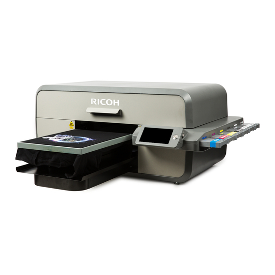
- Page 1 RICOH Ri 3000 Ri 6000 USER MANUAL For safe and correct use, be sure to read the Safety Information in Safety Information and Quick Installation Guide before using the machine. Version 1.0...
-
Page 2: User Manual
RICOH Ri 3000 & RICOH Ri 6000 Direct to Garment Printer User Manual Copyright © 2017 AnaJet, Inc. -
Page 3: Table Of Contents
Table of Contents How to Read Manuals ............................ 7 Safety Symbols for This Machine ......................8 Safety Information for This Machine ....................9 Safety during Operation ..........................9 Safety Precautions to Be Followed ....................10 Environments where the machine can be used ................... 10 Handling power cords and power plugs ....................... - Page 4 1: AnaRIP Raster Image Processor ........................ 71 2: Printer Performance ..........................71 3: Using the RICOH Ri 3000 and RICOH Ri 6000 AnaRIP Program for Printing Light Garments....71 4: AnaRIP Advanced features ........................83 5: Loading Garments on the Print Table ....................... 87 6: Removing Garments from the Print Table ....................
- Page 5 7: Dark Garment Washing ........................... 106 Chapter 8: Hot Folders ......................107 1: Creating a template ..........................107 2: Establish Hot Folder Location ......................... 108 3: Define Holder Folder Settings ......................... 108 Chapter 9: Maintenance and Transportation ................113 1: Technical Notes on White Ink Maintenance ................... 114 2: Maintenance Schedule ...........................
- Page 6 Appendices: .......................... 161 1: Appendix 1 .............................. 161 2: Appendix 2 .............................. 167 3: Appendix 3 .............................. 168 4. Appendix 4 ………………………………………………………………………………………………………………………………………. 169...
-
Page 7: How To Read The Manuals
How to Read the Manuals Disclaimer Contents of this manual are subject to change without prior notice. To the maximum extent permitted by applicable laws, in no event will the manufacturer be liable for any damages whatsoever arising out of failures of this machine, losses of the registered data, or the use or non-use of this product and operation manuals provided with it. - Page 8 Safety Symbols for This Machine The meanings of the safety symbols for this machine are as follows: Caution Prohibition General mandatory action sign Do not touch Caution, risk of having hands or arms caught Caution, risk of electric shock Caution, hot surface Warning;...
-
Page 9: Safety During Operation
Safety Information for This Machine Safety during operation In this manual, the following important symbols are used: Indicates a potentially hazardous situation which, if instructions are not followed, could result in death or serious injury. Indicates a potentially hazardous situation which, if instructions are not followed, may result in minor or moderate injury or damage to property. -
Page 10: Safety Precautions To Be Followed
Safety Precautions to Be Followed Environments where the machine can be used • Do not use flammable sprays or solvents in the vicinity of this machine. Also, avoid placing these items in the vicinity of this machine. Doing so could result in fire or electric shock. •... -
Page 11: Safety Symbols For This Machine
• It is dangerous to handle the power cord plug with wet hands. Doing so could result in electric shock. • Touching the prongs of the power cable's plug with anything metallic constitutes a fire and electric shock hazard. • The supplied power cord is for use with this machine only. Do not use it with other appliances. Doing so could result in fire or electric shock. -
Page 12: Safety Information For This Machine
Handling the main machine • Keep infants away from polythene materials (bags, etc.) used to wrap the machine and its accessories. Suffocation may result if polythene materials are brought into contact with the mouth or nose. • If the machine emits smoke or odors, or if it behaves unusually, you must turn off its power immediately. -
Page 13: Handling Power Cords And Power Plugs
• After opening the top cover, use the prop to keep the cover raised so that it does not close unexpectedly. Otherwise, your hand caught may be caught between the cover and the machine. • Make sure that the top cover is closed, and then turn on the power switch on the back of the machine. -
Page 14: Handling The Machine's Supplies
• Do not attempt to disassemble or modify this machine. Doing so risks burns and electric shock. • Do not open the cover while the machine is operating. Doing so might cause your hand or fingers to get trapped in the machine, and an injury might occur. Handling the machine's supplies •... -
Page 15: Adjustment
items may result. Adjustment • When moving the Print Table, be careful so that your hands or fingers are caught with it. Otherwise, injury may result. • When adjusting the machine feet to level the machine, be careful so that your hand is not caught between the machine foot and stand. -
Page 16: Safety Labels Of This Machine
Safety Labels of This Machine This section explains the machine’s safety information labels. Positions of WARNING and CAUTION labels This machine has labels for WARNING and CAUTION at the positions shown below. For safety, please follow the instructions and handle the machine as indicated. Front 1. -
Page 17: Machine's Interior
Machine’s Interior 6. After opening the top cover, use the prop to keep the cover raised so that it does not close unexpectedly. Otherwise, your hand may become caught between the cover and the machine. 7. Do not place your hand or fingers into the unit. The moving parts inside may cause injury. 8. - Page 18 10. Remove the part indicated by the label before the machine is first turned on. Otherwise, there is the risk of breakage of the machine. 11. Do not touch the circuit board. Doing so could result in injury.
- Page 19 12. Be careful so that your hand is not caught with the main scanning pulley. If it is caught, injury may result.
-
Page 20: Symbols For Power Switch
Symbols for Power Switch Symbols for power switch that are used for this machine are as follows: I: POWER ON O: POWER OFF... -
Page 21: User Notes
User Notes • During operation, do not touch the carriage. Do not put your hand into the gap between the top cover and Print Table. • For information about how to use the heat press device, see the manual. • When removing the fabric, be careful so that your clothing is not stained with ink. If your clothing comes into contact with ink, wash the stained area with cold water. -
Page 22: Laws And Regulations
Other Information for This Machine Laws and Regulations Legal Prohibition Do not copy or print any item for which reproduction is prohibited by law. Copying or printing the following items is generally prohibited by local law: bank notes, revenue stamps, bonds, stock certificates, bank drafts, checks, passports, driver's licenses. The preceding list is meant as a guide only and is not inclusive. - Page 23 • WARNING: Although the laser used in the Ri 3000 and Ri 6000 printer is low power, exercise care so that laser does not shine directly into the eyes. The laser can cause injury. • CAUTION—Use of controls or adjustments or performance of procedures other than those specified herein may result in hazardous radiation exposure.
- Page 24 Continuous Wave (CW) mode. The maximum output power of the light source is 1 milliwatt. • WARNING: Although the laser used in the Ri 3000 and Ri 6000 printer is low power, exercise care so that laser does not shine directly into the eyes. The laser can cause injury.
- Page 25 Noise Levels The following table quantifies the noise levels for various of RICOH Ri 3000/6000 system. Component Noise level RICOH Ri 3000/6000 62 dB(A)
-
Page 27: Chapter 1: Product Information
Chapter 1: Product Information Congratulations on your purchase of a RICOH Ri 3000 or RICOH Ri 6000 Garment Printer. Ricoh is committed to providing our customers with the best in training materials and through this User Manual it is our aim to get you up and printing in the shortest time possible. For additional training, we recommend you contact your RICOH Ri 3000/ Ri 6000 dealer for additional training courses. - Page 28 CAUTION FCC Statement (USA): Note: This equipment has been tested and found to comply with the limits for a Class A digital device, pursuant to Part 15 of the FCC Rules. These limits are designed to provide reasonable protection against harmful interference when the equipment is operated in a commercial environment.
- Page 29 User Information on Electrical & Electronic Equipment Users in the countries where this symbol shown in this section has been specified in national law on collection and treatment of E-waste Our products contain high quality components and are designed to facilitate recycling. Our products or product packaging are marked with the symbol below.
- Page 30 CE Marking Traceability Information (For EU Countries Only) Manufacturer: RICOH Company, Ltd. , Nakamagome 1-chome, Ohtaku, Tokyo 143-8555, Japan Importer: Ricoh Europe PLC 20 Triton Street, London. NW1 3BF, United Kingdom RICOH Company, Ltd. Note for the Battery and/or Accumulator Symbol (For EU countries only) In accordance with the Battery Directive 2006/66/EC Article 20 Information for end-users Annex ll, the above symbol is printed on batteries and accumulators.
-
Page 31: 2: Operation Environment Requirements
2: Operation Environment Requirements Please establish these requirements in your print area before setting up your printer and filling it with ink. Temperature (printer): Operation (with inks loaded): 59°F to 90 °F (15°C to 32°C) Storage (without ink): 14° F to 104° F (-10°C to 40°F) Temperature (storing inks): 41°F to 90°F (5°C to 32°C) Humidity (printer):... -
Page 32: 3: System Requirements
RICOH Ri 3000/Ri 6000 printers are designed to be used with a PC running Windows Vista, Windows 7, Windows 8 or Windows 10 Operating System. The programs needed to run your Ri 3000 or Ri 6000 printer do not work on an Apple computer unless it is running Windows emulation software such as Parallels, Bootcamp or other software that allow one to run the Windows Operating System on Apple computers. -
Page 33: 6: Customer Training Checklist
Thus, the performance of Ricoh approved inks on a specific fabric may vary significantly and the ink may not work for a given garment type. Ricoh does not guarantee its inks will work on a specific garment. If you are printing on an unfamiliar fabric, it is always necessary to test your results before beginning a production run. -
Page 34: Chapter 2: Startup Of A New Printer
Chapter 2: Startup of a New Printer 1: Unpacking the Printer • The machine weights around 81.6 kg (180 lb.). • Four or more people are required to lift the printer. When moving the printer, lift it slowly so that you do not strain yourself. -
Page 35: 2: What's In The Box
1 RICOH Ri 3000/Ri 6000 Printer o 1 Power cord (US) o 1 USB cable o RICOH Ri 3000/Ri 6000 Safety Information and Quick Installation guide for your printer o Cleaning Applicators (1 pack) o Wiper Blade (set of 2) -
Page 36: 3: What Else Is Needed
3: What Else is Needed The following items will also be needed for your RICOH Ri 3000/Ri 6000 printer operation: 1. Electronic hygrometer/thermometer (to monitor the relative humidity of the room the printer is operating in). 2. PC computer with Vista, Windows 7, Windows 8 or Windows 10 operating system. - Page 37 Leveling the Printer • When adjusting the machine feet to level the machine, be careful so that your hand is not caught between the machine foot and stand. If it is caught, injury may result. Leveling the Printer Before the printer is turned on, the printer should be leveled. There are 6 adjustable feet under the bottom casing of the printer that are used level the printer.
- Page 38 Connecting Cable Connections • Do not use any power sources other than those that match the specifications shown in this manual. Doing so could result in fire or electric shock. • Do not use any frequencies other than those that match the specifications shown. Doing so could result in fire or electric shock.
- Page 39 Plug in the provided power cord to a surge protector connected to a wall outlet. Ri 3000/Ri 6000 printer power supplies will accommodate voltages ranging from 100 to 2450 volts. Next, plug the power cord into the power entry module in the rear of the printer.
-
Page 40: 5: Before Filling The Printer With Ink
After pressing the <POWER> key on the control panel, the control panel display will show the Ri 3000/Ri 6000 flash screen and then it will initialize and finish at the Jobs Screen. During this initialization observe the printer movement through the table opening. You should see the print carriage move to the right and then back to its home position and then the print table will move out to its load position. - Page 41 Cleaning Solution from the system. Do not install the ink cartridges at this time. The Ri 3000 and Ri 6000 printers utilize a fully circulating ink delivery system for the White Ink Channels that uses 2 sets of tubing. The first set is called the Print side and the second set the Purge side.
- Page 42 Installing Ink Cartridges We will now install the ink cartridges. All Ricoh authorized inks are intended for single use ONLY. The ink cartridge bay is located on the right-hand side of the printer. For US machines, new printer is shipped with 6 Ricoh authorized ink cartridges: 1 of each color: cyan, yellow, magenta, black and 2 white.
- Page 43 Figure 2.6-6: Ink Cartridge Bay Configuration Once you insert the ink cartridges, check the bottom of the Control Panel display that all of the ink bays show as GOOD under each color. If it does not, pull out the ink cartridge and reinsert it into the ink bay and press the color icon to recalibrate.
-
Page 44: 7: Performing A Nozzle Check
• After opening the top cover, use the prop to keep the cover raised so that it does not close unexpectedly. • Make sure that the top cover is closed, then turn on the power switch on the back of the machine. Before closing the cover, turning on the power may cause the machine to operate and cause injury. - Page 45 If you have a Ri 3000 you will see one channel of each of your colors printed on the paper and one block from each of the whites printed on the table (See Figure 2.7-3 below). If you have an Ri 6000 you will see two channels of each color printed on the paper and four channels of white printed on the table.
-
Page 46: 8: Printer Software Program Requirements
Figure 2.7-4: Print Head Clean Menu If your nozzle check only shows that the white ink channels are not firing fully then select Clean White Channels, indicated by the orange arrow. If you need to clean any of the CMYK channels, select the CMYK channel clean indicated by the green arrow. -
Page 47: 9: Adding A New Printer To Anarip
Figure 2.9-1: View Manage Printers Figure 2.9-2: Printer Configuration 10: Choosing Ink Sets Under Manage Printers you can choose which ink set profiles you wish to use. PowerBright Plus ink set is designed to be optimized for Ricoh authorized Inks. - Page 48 Figure 2.10-1: Choosing Ink Sets Before proceeding to Printer Operations, get familiarized with the Printer Controls in Chapter 3.
-
Page 49: Chapter 3: Printer Controls
The main power switch is on the rear left side. Switch the power on. 2: Control Panel The Ri 3000 and Ri 6000 Control Panel consists of a touch LCD display, a circular power/print button and a USB port on the right side. The control panel layout is shown below in (Figure 3.2-1). - Page 50 times, even when the printer is not used. Keeping the power on enables the printer to perform periodic minimal self-maintenance routines that help prevent the print head from drying out.
-
Page 51: 3: Buttons
3: Buttons The <POWER> button powers on the print engine. Make sure you have switched the Master Power Switch on the back of the printer first. Power button should glow with a blue light. The <TABLE> button moves the Print Table back and forth. Pressing it while the Print Table is moving will stop the table. -
Page 52: Chapter 4: Printer Operation
Next press the Control Panel <POWER> button to turn on the printer. A splash screen will appear on the display showing the Ricoh logo and the power up sequence will begin. The Print Table will move forward to the Load Position. When the power up sequence is properly completed, the following display (in Figure 4.2-1) will show in the LCD. -
Page 53: 4: Moving Print Table
4: Moving Print Table • When moving the Print Table, be careful so that your hands or fingers are caught with it. Otherwise, injury may result. Pressing the <TABLE> button on the Control Panel will move the Print Table in one direction. - Page 54 Basic Printing Operation Prepare the print file using your image editing software and send it to the printer through your Ri 3000 or Ri 6000 AnaRIP program. Refer to Chapter 6.3: Using the Ri 3000 and Ri 6000 AnaRIP Program for Printing Light Garments.
-
Page 55: 6: Safety Warnings
LOAD FROM USB FRONT or USB BACK; this will only appear when USB flash drive is inserted into the Ri 3000 or Ri 6000 Control Panel. Images that have been saved to the Control Panel can also be printed from the SELECT FROM INTERNAL STORAGE function. - Page 56 Front 1. Do not reach far inside the unit. Moving parts inside may cause injury. 2. Do not reach far inside the unit. Moving parts inside may cause injury. 3. Keep your eyes away from the laser aperture so that the laser does not shine directly into your eyes.
- Page 57 Machine’s Interior 6. After opening the top cover, use the prop to keep the cover raised so that it does not close unexpectedly. Otherwise, your hand may become caught between the cover and the machine. 7. Do not place your hand or fingers into the unit. The moving parts inside may cause injury. 8.
- Page 58 10. Remove the part indicated by the label before the machine is first turned on. Otherwise, there is the risk of breakage of the machine. 11. Do not touch the circuit board. Doing so could result in injury. 12. Be careful so that your hand is not caught with the main scanning pulley. If it is caught, injury may result.
- Page 60 Figure 4.6-1: Obstruction Sensor and Laser Figure 4.6-2: Message Received When Obstruction Detected...
- Page 61 Figure 4.6-3: Message Received When Cover is Open Cover Open: • When maintenance is performed, the carriage may move while the top cover is open. Do not touch the carriage while it is moving. Touching it may result in injury. The cover open message appears when a print job, print head clean, ink fill or nozzle check is performed with the cover open.
-
Page 62: Chapter 5: Printer Settings
Press the <MENU> button and select Settings. Figure 5.1-1: Printer Settings 2: Language Select the System tab to access the different Languages available for the Ri 3000 and Ri 6000. Scroll through the drop down to find the language desired. -
Page 63: 3: Pre-Print Checks
Cartridge Check: Before printing a job your Ri 3000 or Ri 6000 printer will make sure all six of your cartridges are in a ready state. The printer will make sure all of the carts are inserted and have plenty of ink to complete the print. -
Page 64: 4: Wipe After Number Of Prints
If you dare to use non-Ricoh authorized inks, you are responsible for any result, including damage, arising out of your use of non- Ricoh authorized inks. Figure 5.3-1: Pre Print Checks Menu Power Voltages: The printer will automatically read the power voltages any time it is about to print to ensure that all of the components required to print the job are receiving enough power. -
Page 65: 5: Cap Head Delay
Figure 5.4-1: Wipe After Number of Prints 5: Cap Head Delay You can also control how long the printer will go before the maintenance station engages to seal off the print- heads. The default for this setting is two minutes. Figure 5.5-1: Setting Cap Head Delay The maintenance station seals off the print-heads when the printer is idle;... - Page 66 6: Exhaust Fan You may have noticed two exhaust fans in the back of your printer. Figure 5.6.-1: Exhaust Fans The purpose of these fans is to collect and filter any ink overspray that comes off of the shirt or Print Heads.
- Page 67 With the Ri 3000 and Ri 6000 printers it is not necessary to wait until one job is complete before sending the next job. While the first job is printing, you can prepare and send another print job. If the second job is transferred and ready before the first job is finished printing you will see the message “New Job...
- Page 68 Figure 5.7-2: New Job Available If the Auto Advance is on in your printer settings, the second job will appear on your print screen as soon as the first job is finished printing. Figure 5.7-4: Wait for Entire Job By default, the printer will wait for the entire job to transfer before you are able to hit the print button. You have the option of changing this from Yes to No using your right arrow key.
-
Page 69: 8: Network Connection
8: Network Connection Figure 5.7-4: Wait for Entire Job You can also set up your Network Connection through your Printer Settings menu. To adjust your network settings, select Network tab in the Settings Menu. You will have the option of setting your Ethernet Mode to Dynamic, or Static. - Page 70 Static: Static IP address is used when the router has reserved a specific address for the printer. This allows printer to maintain a constant connection with router. Dynamic: IP address is assigned by the router randomly whenever the printer has been disconnected from the network for a certain duration of time.
-
Page 71: 9: Printer Number
This setting allows you to assign your printer a specific number. This feature is very helpful when printing with multiple Ri 3000 or Ri 6000 printers through a network connection. If each printer is assigned a specific number, you can then choose which printer to send the print job to by selecting the... -
Page 72: 10: Set Time Zone
Once selected, you will see two different print counts; the Lifetime Count and the Project Count. The Lifetime Count is the total number of prints your Ri 3000 or Ri 6000 printer had completed; this number cannot be changed or reset. Your project count can be reset at any time. This count can be used to keep track of the prints you have done for any particular project or during a specific period of time. - Page 73 Figure 5.12-1: Reset Print Counters...
-
Page 74: Chapter 6: Light Garment Printing Process
Chapter 6: Light Garment Printing Process 1: AnaRIP Raster Image Processor Ri 3000 and Ri 6000 AnaRIP printing software is provided for online download at: http://AnaJet.com/downloads . AnaRIP is a raster image processor (RIP); it is software which converts the graphic design to bitmap data suitable for printing. In the process, smoothing or interpolation algorithms are applied to the graphic data, ink drop size and exact placement of inkjet ink drops are determined. - Page 75 AI or PSD you must flatten all of the layers of you image and save this version for printing your complete image. Open the Ri 3000 or Ri 6000 AnaRIP program from your desktop. Once the program is open you can now place the graphic you would like to use by selecting Place Image under the File drop down in the upper left corner of the program.
- Page 76 Figure 6.3-4: Textile Color Selection Figure 6.3-5: True View on Different Textile Color As you can see below, the garment color affects the final print color of your image. True View is a very powerful feature of AnaRIP and will assist you in determining whether or not you will need to use white ink.
- Page 77 If USB is selected in the Printer Name drop-down then when the print button is pressed the job will RIP to the Ri 3000 or Ri 6000 printer that is currently connected to the computer through the USB cable.
- Page 78 Figure 6.3-8: Platen Size Most printing will be done using the Main platen which measures 14” x 18”. For printing youth size shirts and sleeves, you can install the Youth Print Table which is 8.5” x 12” in size, or the Sleeve Print Table which is 4”...
- Page 79 Figure 6.3-10 Platen Placements When printing with the Small Print Adapter, remember to adjust the Print Table’s height. You can select either Left or Right portrait orientation Pocket Platens from the Platen size selection in AnaRIP. Figure 6.3-10: Print Table with Pocket Adapter Layout and Print Origin •...
- Page 80 position items to print. The Speed, Fine and Super Fine modes print the image using the same volume of ink but they print using smaller steps according to the higher quality which can produce better image quality. Please note that the print speed will be affected by the higher settings. You will now need to select a Variable Dot Range, the default setting is Narrow.
- Page 81 The input ICC profile translates color data created on a device (such as a digital camera) into the PCS, profile connection space. The RIP uses the output ICC Ink Set Profile (PowerBright or PowerBright Plus) to convert from the PCS into the native color space of the Ri 3000 and Ri 6000.
- Page 82 Figure 6.3-15: Color Controls Input Color Profile Figure 6.3-16: ICC Input Profile Images created in Photoshop most often contain a built a profile for the specific color space the image was designed in. The rip allows you to change use a different ICC profile instead of the ICC profile that is part of the image file.
- Page 83 Figure 6.3-17: Rendering Intent Rendering intent specifies the rendering intent that this step should associate with the job. Rendering intents inform the printer what action to take when a print job includes colors that lie outside the color range of the printer. Perceptual (default): The printer adjusts all the colors in the image so they are all in the color range of the printer and maintain their color relationships to each other.
- Page 84 Figure 6.3-19 & 6.3-20 Brightness Adjustment Brightness Up Brightness Down Figure 6.3-19 Figure 6.3-20 Figure 6.3-21 & 6.3-22 Contrast Adjustment Contrast Up Contrast Down Figure 6.3-21 Figure 6.3-22 Figure 6.3-23 & 6.3-24 Saturation Adjustment Saturation Up Saturation Down Figure 6.3-23 Figure 6.3-24 Figure 6.3-19 to 6.3-24: Color Adjustments Previews Because we are printing light garments, the Underbase Tab will not be used at this time.
- Page 85 Design File it will not be unable to locate it.) You also have the option to save a Template, this will just save the settings and when a new design is started these setting can be applied to the new design. At this point you can also press Print or Print to File.
-
Page 86: 4: Anarip Advanced Features
A file that has been previously been sent directly to the printer can be retrieved from the printer's Internal Storage for reprinting Select Job from Internal Storage. You can now scroll through all of the print jobs and select the file you want to print and press <SELECT> (Figure 6.3-27). The specific job file will come up in the display, adjust the Copies to Print and then press either the green <PRINT>... - Page 87 By default, the RIP has two default ink sets, PowerBright and PowerBright Plus Ink Sets. PowerBright is optimized for Ricoh authorized ink. If you end up developing your own color profile and/or color curves to get your desired results, you will need to add an additional Ink Set Profile.
- Page 88 Figure 6.4-5: Ink Set Editor Manage Color Profiles To add a new ICC color profile, click on the plus icon and locate the location of the file on the PC. Profiles can be created through the use of X-Rite IProfiler or other similar products. Figure 6.4-6 ICC Color Profiles.
- Page 89 Figure 6.4-7: Color Curves Curve Editor The curve editor allows the user to develop their own color curves which can be imported into the rip. Figure 6.4-8 and Figure 6.4-9: Curve editor Figure 6.4-8 Figure 6.4-9 Remember to press the Apply button so the changes are saved for the next print job. When you Enable ICC preview within the AnaRIP, this is modifying the current screen settings on your computer to display our color profile used for the output of our AnaRIP color profile.
-
Page 90: 5: Loading Garments On The Print Table
Figure 6.4-10: Selecting ICC Preview 5: Loading Garments on the Print Table To load a t-shirt for a standard front/center print, first remove the hoop from the print table. Place the t-shirt face up on the table with the top collar closest to you and pull the collar off the end of the table so that it just falls off the edge of the table. -
Page 91: 6: Removing Garments From The Print Table
Pull by the edges to ensure proper placement and that it is flat on the heat press, minding not to touch the wet ink. Cover the garment with a sheet of SoftTouch heat press paper, for Ricoh authorized ink. Close the press and heat the printed garment for 40 seconds at 356ºF or 180ºC. - Page 92 Ricoh Authorized Ink Temperature Time 356 ˚ F or 180 ˚ C Light Shirt with Heat Press 40 seconds Light Shirt with Conveyer Dryer Printed image must reach Varies 330 ˚ F or 165 ˚ C Figure 6.7-1: Heat Curing Temperature and Time Variations for Light Garments...
-
Page 93: Chapter 7: Printing On Dark Garments
Chapter 7: Printing on Dark Garments 1: Basic Dark Garment Printing Process Before you start any print job you will want to make sure you have proper ink flow and print quality to assure the best results. This will require that you perform a Nozzle Check, possibly followed by a Print Head Clean if needed. -
Page 94: 2: Maintenance Of White Ink
Place the dark garment on the Print Table. Send the print job from the PC, using the Ri 3000 or Ri 6000 AnaRIP program or load the print job from a USB drive. Press the <PRINT> button when the blue Print Ready LED lights up to print the white ink Undercoating. -
Page 95: 3: Scheduled Maintenance
It is very important to follow the printer maintenance schedule. If neglected, it may become necessary to ship the unit back to a RICOH Ri 3000/Ri 6000 repair facility and put the printer through an extensive and expensive refurbishment process. These maintenance procedures are presented in a detailed manner in Chapter 9: Maintenance and Transportation. - Page 96 You will need the following for Pre-treatment Application: A well-ventilated room. Good ventilation is essential for worker comfort and health. Application of Pre- treatment Liquid outdoors is not recommended on windy days as it can cause uneven application. It is recommended that a room away from the printer be dedicated to the application of pre-treatment so that the spray will not affect your printer.
-
Page 97: 5: Dark Garment Ri 3000 Or Ri 6000 Anarip Settings
Import and set up your image as described in the previous chapter (see Chapter 6: Light Garment Printing Process) When printing onto a dark garment or any garment that needs white ink to be printed the Enable white ink checkbox needs to be checked in the Ri 3000 and Ri 6000 RIP program. Figure 7.5-1: Underbase When you enable white ink three things will happen. - Page 98 Figure 7.5-2: View After Enabling White Ink Figure 7.5-3: Underbase Tab Settings By default the Content based checkbox will be checked and your Quality should be set to Fine. The Variable Dot Range will be set to Narrow. The Bi-directional Underbase printing checkbox will be checked for optimum speed when printing the Underbase.
- Page 99 Figure 7.5-4: Content Based Checked Figure 7.5-5: Content Based Unchecked Figure 7.5-6: White Ink Enabled View Options Using the View selection you can monitor how your adjustments to the Underbase will affect your printing results by selecting the Underbase and TrueView option (Figure 7.5-6). The Underbase and TrueView images should now be visible in the preview screen.
- Page 100 (Figure 7.5-8 to 7.5-17). Note that some of the functions are disabled when Content Based is not checked. Figure 7.5-7: Underbase Adjustments Color Contrast will affect the amount of white used in the image and can be adjusted with the Color Contrast slider bar.
- Page 101 Figure 7.5-9: Color Contrast Slider Down Opacity Contrast is only active when your image has a soft or semi-transparent edge or the image has semi-transparent colors in it. Moving the slider bar to the left will reduce the amount of white Underbase beneath these areas to help create a smoother blend.
- Page 102 Figure 7.5-11: Opacity Contrast Down Choke combats the phenomena that when printing the White ink Underbase onto a garment the garment will expand and swell. This is the same for any type of garment printing including screen printing. The Choke setting slightly reduces the outside dimensions of the Underbase so that white ink does not appear outside the prints edges of the final color pass.
- Page 103 Figure 7. 5-13 Choke Increased to 2 Figure 7. 5-14 Choke at 0 Individual Color Adjustments By selecting a color from this drop down menu you are able to increase or decrease the amount of white ink Underbase that will print under that color. This will help you bump up or bring down certain colors in your final print.
- Page 104 Figure 7.5-15: Color Adjusted Up Figure 7.5-17: Pure White Adjustment Pure White is set at 100 by default to print the whitest ink in the pure white areas of your image. If desired this can be lowered here. (Figure 7.5-17) Remember you can still further adjust your image by changing the settings on the Color Adjustments Tab.
- Page 105 Figure 7.5-19 White Highlight Enabled Figure 7.5-20 Highlight Layer View White Highlight allows for a second layer of pure white to be printer during the color layer, allowing for a brighter white. If using white highlight, make sure there is dead pixel space between any large amounts of pure white and any CMYK color as it may cause white ink to mix the color at the edge.
- Page 106 Figure 7.5-21: Select Border Color to be Removed You can also select to remove a Border color. This removes a contiguous color up to when it changes to another color. Please note that better results will be achieved by using your image editing software to create transparencies.
- Page 107 Figure 7.5-23: Color Layer Wait set to 0 Seconds Figure 7.5-24: Color Layer Wait set Manual...
-
Page 108: 6: Set The Image With Heat Treatment
Figure 7.5-25: Color Layer Wait Time 6: Set the Image with Heat Treatment User’s Notes • For information about how to use the heat press device, see the manual. In order to cure the ink so that your images will be color-fast when washing, it is necessary to heat treat the image so that the image bonds with the garment. -
Page 109: 7: Dark Garment Washing
Ricoh Authorized Ink Temperature Time Dark Shirt with Heat Press 330˚F or 165˚C 90 seconds Dark Shirt with Heat Press Printed image must reach Varies 330˚F or 165˚C Figure 7.6-1: Heat Curing Temperature and Time Variations for Dark Garments 7: Dark Garment Washing A properly printed dark garment can last dozens washes without noticeable fading if washed properly. -
Page 110: Chapter 8: Hot Folders
Chapter 8: Hot Folders Hot Folders, also known as Auto RIP Folders, are folders linked to a particular Template File. Images are dropped into the Hot Folder and are automatically ripped based on the predefined settings of the Template File; AnaRIP must be open for the Hot Folders to operate. Based on the Hot Folders settings the ripped file is sent to a folder on the PC or directly to the printer. -
Page 111: 2: Establish Hot Folder Location
2: Establish Hot Folder Location Figure 8.2-1: Create Folders Hot Folders require a location on a host computer for AnaRIP to RIP files from and may require additional folders to send the original image file to and a folder to send complete ripped files to. 3: Define Holder Folder Settings Figure 8.3-1 Edit AutoRIP Folders Figure 8.3-2 Create New AutoRIP... - Page 112 To Establish a Hot Folder, go to the QUEUE and click on Edit AutoRip Folders. Then select New. Figure 8.3-3: AutoRIP Editor Fill out the AutoRIP Folder Editor settings according to how you wish to utilize the Hot Folder.
- Page 113 Figure 8.3-4 Input File handling The Input file handling after process section dictates what to do with the original Input File, delete or move to a new folder location. Figure 8.3-5 and Figure 8.3-6: Graphic File Handling Figure 8.3-5 Figure 8.3-6...
- Page 114 The Graphic file handling section what determines what changes are applied within the RIP. As previously stated, the template file contains all relevant RIP information, image offsets, scaling, Underbase variables and color adjustment variables. Based on the positioning setting, Align to top position offset, Fit in placement box, aligned to top, Fit in placement box, centered, the graphic will be positioned differently in the print output.
- Page 115 Figure 8.3-9 Enable AutoRIP Output Once the RIP settings have been established make sure to enable Hot Folders by double clicking on the Hot Folders’ name. The Hot Folders can also be used as driver to send already ripped files to a designated destination.
-
Page 116: Chapter 9: Maintenance And Transportation
Chapter 9: Maintenance and Transportation • Keep infants away from polythene materials (bags, etc.) used to wrap options and cartridges/bottles for ink, cleaning solution, HV storage solution, and pretreatment liquid. Suffocation may result if polythene materials are brought into contact with the mouth or nose. •... -
Page 117: 1: Technical Notes On White Ink Maintenance
The inks must not touch open air; otherwise the Titanium Dioxide based ink will agglomerate and clog the ink delivery system and Print Head. RICOH Ri 3000/Ri 6000 printers use sealed ink cartridges protect inks. Open ink bottles or refillable bulk ink cartridges will expose the ink to open air causing... -
Page 118: 2: Maintenance Schedule
DAILY MAINTENANCE: Using the Ri 3000 or Ri 6000 Control Panel, print a Nozzle Check daily (see chapter 2: section 7). Perform Print Head cleans as needed. Usually one or two Print Head Cleans will clear the nozzles and achieve a good Nozzle Check Pattern. -
Page 119: 3: Required Maintenance
The printer firmware at times may need to be updated. Check for updates on www.AnaJet.com/downloads or contact your RICOH Ri 3000/Ri 6000 distributor for more information. Print and use the MAINTENANCE CHECKLIST included in Appendix 2. ... - Page 120 Before the cleaning operation, obtain the Cleaning applicators. These are low lint urethane cleaning swabs made for RICOH Ri 3000/Ri 6000 Maintenance cleaning. Discard Soiled Cleaning Applicators after use. We also recommend some lint free wipes, Ricoh authorized Cleaning Solution and lubricant.
- Page 121 The cleaning Applicator can be dipped in Ricoh authorized Cleaning Solution if there are stubborn dried inks deposits in the area. To avoid contamination, never dip soiled Cleaning Applicators in the Cleaning Solution bottle. Do not use any sharp objects or solvent based cleaners like alcohol to remove dried ink deposits around the Capping Rings as this could damage them or dry them out and cause them to crack.
- Page 122 Figure 9.3-5: Clean Highlighted Areas with Swabs Figure 9.3-6: Bubble Breaker At this time the plastic bubble breakers will also need to be removed and cleaned. To remove the bubble breaker, use a flat head screwdriver and lift up from either the top or bottom of the oval. Never lift from the center, as the piece will break in half due to the high pressure.
- Page 123 Do not use any solvent based cleaners or isopropyl alcohol as they may damage the protective coating on the print head, instead you may use Ricoh authorized Cleaning Solution. Remove any ink residue accumulated on the Nozzle Plate. (Figure 9.3-8) When the Print Head Plate is clean you should see the bare metal of the plate.
- Page 124 Figure 9.3-10: Cleaning Print Heads Print heads should only be cleaned with Ricoh authorized Urethane Cleaning Applicator and Cleaning Solution. To clean the print heads, gently wipe the nozzle with light pressure Figure 9.3-11: Flushing the Maintenance Station When flushing the maintenance station, we will need to activate the maintenance station pump while the carriage is released.
- Page 125 To access the Advanced Menu press <MENU> button and then press the <Print> button 8 times. The Advanced Menu will appear. Be sure to not have a print job loaded on the screen, as the Print will begin once you press the print button. Figure 9.3-13: Maintenance Station manual control Turn Pump On Select Maintenance station and then select Pump On for Either CMYK or White.
- Page 126 Figure 9.3-15: Main Menu Figure 9.3-16: Secure Carriage Cleaning the Encoder Strip The Encoder Strip located on the back of the carriage should be cleaned on as needed if becomes covered in ink mist or if ink has landed on the strip. In order Clean the encoder strip you will need to first release the carriage.
-
Page 127: 4: Ink Levels And Cart Replacement
If the cleaning the inside of the encoder board is needed to remove any lint, gently remover the encoder strip from the encoder board and thread a lint free wipe through the sensor. Cleaning with a lint free wipe and 91% isopropyl alcohol will help remove any ink mist that has gotten on the sensor. - Page 128 Figure 9.4-1: Ink Cartridge Problem Replace the ink cart that stated shown to be Very Low or Empty. Once replaced, select the color replaced to recalibrate the printer reading. Figure 9.4-2: Ink Empty Message...
- Page 129 Ricoh recommends the use of Ricoh authorized Ink cartridges which have been specifically developed for the RICOH Ri 3000 and RICOH Ri 6000 printer. Use of other inks or tampering of the ink cartridge will not only produce poor quality prints but may damage your printer. Ricoh is not responsible for any damaged caused to the printer through the use of third party inks.
- Page 130 Figure 9.4-4: Unauthorized Ink Message To replace ink cartridges Once the LCD control panel has indicated a cartridge is low or empty replace using the correct color into the correct ink bay slot, or you will not be able to continue printing. Cartridge color assignment is located above the ink bay with a matching colored circle.
-
Page 131: 5: Switching From Ink To Cleaning Solution Using The Startup Fill Function
The Ricoh authorized Cleaning Solution cartridges expire three years from the manufacturing date. Gently shake the Ricoh authorized ink cartridge a few times to assure that the pigment is in solution. Note that Cleaning Solution cartridges should not be shaken as it may cause foaming. ... -
Page 132: 6: Waste Ink Tank And Drip Absorbers
Continue running the fills until the purge and print lines are crystal clear. The Ricoh authorized cleaning solution is clear and the ink does not stain the tubes so lines which have been flushed thoroughly are completely transparent. - Page 133 Follow the procedure below to remove the waste ink: Figure 9.6-1: Waste Tank Full Message Remove the Waste Ink Drain Tube from the storage area located inside the printer next to the waste ink tank (See Figure 9.6-3). Figure 9.6-2: Waste Ink Tank and Reservoir Ink Tank Location...
- Page 134 External Waste ink drain tube location Figure 9.6-3: Waste Ink External Drain Tube Location Figure 9.6-4: Waste Ink Tank Find a receptacle to hold the waste ink and place the non-coupler end of the waste ink tube and place it inside. Insert the Waste Ink Drain Tube coupler into the Waste Ink Drain, on the back of the printer.
- Page 135 Figure 9.6-5: : Insert Waste Ink Drain Tube Figure 9.6-6: : Waste Ink Tank into Waste Ink Drain It is a good practice to clean the Waste Ink Tank every 6 months and replace it once a year. The white waste ink pigment will settle at the bottom of the tank, and reduce the Waste Ink Tank’s capacity.
- Page 136 Checking and Emptying the Waste Reservoir Tank There is an overflow reservoir tank located under the ink mist cover. This tank should be checked monthly and emptied. This tank does not have a sensor, so it is very important to check it on a monthly basis. The tank is attached by Velcro.
-
Page 137: 7: Changing Fan Filters
Do not use a hard or abrasive brush. Do not lubricate the inside of the printer. Unsuitable oil or lubricants can damage the mechanisms. Contact a qualified RICOH Ri 3000/Ri 6000 service technician if lubrication is needed. -
Page 138: 9: Transporting The Printer
The Printer Cleaning Process Turn off the print engine power using the <POWER> key on the Control Panel. When the print engine power down sequence is completed, turn off the Main Power Switch at the rear of the printer. ... - Page 139 Figure 9.9-1: It is important to place the Table and Carriage Retainer before Transport. Move the printer carefully (four people are required). Keep the printer horizontal. Only move the printer on its side when moving through a doorway. When you reach the new destination, make certain the printer is placed on a stable, sturdy and level table.
- Page 140 Long Distance Move Please contact a certified RICOH Ri 3000/Ri 6000 technician to walk you through this process. Replace all of the ink with Cleaning Solution. (See Section 9.5 of this chapter) Drain the Waste Ink Tank. (See Section 9.6 of this chapter) ...
-
Page 141: Chapter 10: Firmware Updates
Chapter 10: Firmware Updates 1: Firmware Menu To access the updates menu, press <MENU> and then go to Maintenance. Press the Firmware tab. Figure 10.1-1: Main Menu Figure 10.1-2: Update Menu 2: Major Control Firmware Updates Control Firmware updates will need to be installed with an USB that has been formatted to FAT 32. This should be done prior to loading the firmware. - Page 142 Download the latest Firmware updates available at http://www.anaJet.com/ downloads Copy the files from .ZIP package to the USB drive. Figure 10.2-3: Firmware Image Figure 10.2-4 Front USB: Insert USB Files Once the firmware has been loaded on the USB, under <ABOUT PRINTER> menu, select Update. The printer will begin the update process.
- Page 143 Figure 10.2-6: Update Status Successful The update will install the firmware and verify the installation of the files. Once finished, the printer will power down. See Figure 10.2-6 for an example of the screen you will see during update. Once the USB has been removed, turn on the printer. Be sure to confirm the printer model and firmware version number located under the About Printer menu is the same as the one downloaded from the website.
-
Page 144: 3: Minor Control Firmware Updates
Figure 10.2-8: Firmware Check Points 3: Minor Control Firmware Updates Download the latest Firmware updates available at http://www.anaJet.com/downloads The minor update will consist of an update.signature and an update.zip file and can be installed with an USB Flash Drive. Copy the two files to the root the drive Figure 10.3-1: Firmware Update Files Insert the USB Drive. - Page 145 Figure 10.3-4: Updating Figure 10.3-5: Prepare for Update During the update the printer will verify that the update package and signature files have been found and that it has been installed, once finished the printer will power down. Figure 10.3-6: Update Application Once the printer is off, power on the printer.
-
Page 146: 4: Board Firmware Updates
4: Board Firmware Updates Download the latest Board Firmware updates available at http://www.anaJet.com/downloads The board update will consist of .hex file with file name consisting of the name of the board that will be updated and can be installed on either an USB Flash Drive. Copy the board firmware to the drive. Figure 10.4-1: Board Update File Insert the USB Drive. - Page 147 Once the board firmware has been installed, verify the firmware version. To verify, In the Firmware tab select the board that was updated, the select Read Board Info. Figure 10.4-6: Board Selection Select Get Firmware Info Verify the version number of the board matches the one downloaded from the website. The printer will then need to be powered down and restarted.
- Page 148 Figure 10.4-8: Powering Off...
-
Page 149: Chapter 11: Troubleshooting
Chapter 11: Troubleshooting 1: The Print Engine Does Not Turn On During the print engine power up sequence, the Control Panel Power LED will blink and LCD will display a splash screen. When the print engine properly completes the power up sequence and the blinking Power LED becomes steady on, the Print Table will move forward to the Load Position. -
Page 150: 3: Black Screen
In AnaRIP, go to view printers and press Refresh and verify the printer connection does not say “*not found*”. Figure 11.2-1: Verify Connection 3: Black Screen Figure 11.3-1: Black Screen If a black screen appears upon start-up, turn off the printer from the rear power switch, wait a few seconds and power back on the printer. -
Page 151: 4: Startup Application Error
If there is a cable not plugged in, turn of the machine before reconnecting the cable. If all cables are confirmed to be connected, contact a certified RICOH Ri 3000/Ri 6000 technician. 5: Platform did not lower upon startup Figure 11.5-1: Platform Startup Error... -
Page 152: 6: Home Table Time Out
If all cables are connected and the Table motion Board (located on the back center floor of the printer) does not receive power, the table will not move upon startup and thus results in a home table time out error. Please contact a certified RICOH Ri 3000/Ri 6000 if this error occurs... -
Page 153: 7: Home Carriage Time Out
Figure 11.6-1: Table Timeout 7: Home Carriage Time Out Figure 11.7-1: Carriage Timeout If you receive a Home Carriage Timeout error, verify the grey CanBus cable is plugged to each of the boards of the printer. If all cables are connected and the Carriage Motion Board (located behind the left support column) does not receive power, the carriage will not move upon startup and thus results in a home carriage time out error. -
Page 154: 8: Platform Did Not Lower/Engage
8: Platform Did Not Lower/Engage Figure 11.8-1: Platform Error If the maintenance station platform does not lower or rise during its normal operation, the control panel will display three options: Retry, Cancel, and Ignore Ignore function tells the printer to ignore the sensor and proceed with the next action ... -
Page 155: 9: Failed To Calibrate Head Drive Board Voltage
Figure 11.8-3: Platform Down Figure 11.8-4: Platform Up Limit1 should be 0 after Platform UP is selected and 1 when Platform Down is selected. 9: Failed to Calibrate Head Drive Board Voltage If the printer detects the print voltages are of out of tolerance the printer will attempt to calibrate the head drive voltage. - Page 156 Calibrate Head Voltages. If the Print Head Driver Board fails to calibrate, repeat a maximum of 5 times. If the boards are unable to calibrate, contact a certified RICOH Ri 3000/Ri 6000 technician. Figure 11.9-4 Failed to Calibrate Print Heads...
-
Page 157: 10: Horizontal Banding
Check) If needed perform the necessary Print Head cleaning. Make sure that you are using Ricoh authorized Ink. Check the LCD Control Panel and check for low or empty ink cartridges if any are low or out of... -
Page 158: 12: Prints Are Faint And There Are Gaps
12: Prints are Faint and there are Gaps Make sure that the Ink Level setting in the Ri 3000 or Ri 6000 RIP program is not too low for the media being printed on. If printing with a Narrow Variable Dot Range, switch to Wide. -
Page 159: 15: Printing Is Too Slow
(Load Position) and then push it all the way to the rear (Home Position). Pull and push firmly but do not force it. Check behind the table when it is out for obstructions. If lubrication is needed, do not attempt to lubricate it without the assistance of a certified RICOH Ri 3000/Ri 6000 technician. -
Page 160: 18: The Print Head Nozzles Get Clogged Too Often
18: The Print Head Nozzles Get Clogged Too Often The Ri 3000 and Ri 6000 printer, with its Closed-Loop Ink Delivery System and sealed ink cartridges, is designed to operate without nozzle clogging. But occasional nozzle clogs are inevitable with any inkjet apparel printer. -
Page 161: 19: Information To Provide Technical Support
Figure 11.19-2: Printer Serial Number Ri 6000 Located on the back of the printer is a sticker containing the printer serial number and near the top is the printer type (Ri 3000 or Ri 6000) bubbled in. Printer Firmware Version and Model Type The printer firmware version and model type are located on the main Jobs page. - Page 162 Printer Info Technical support may require you provide information such as last time a clean and printer were performed Figure 11.19-4: Printer Info From the Diagnostics Menu go to section Printer State/Check Sys Log/Check Printer Log/ Printer Info and select Printer Info. Record the information. Printer &...
-
Page 163: 20: How To Get Additional Help
20: How to Get Additional Help Ricoh provides technical support for the installation; setup, operation and troubleshooting of RICOH Ri 3000 or Ri 6000 and AnaRIP printing software as well as Ricoh authorized inks while they are under warranty, free of charge. -
Page 164: Appendices
Appendices: 1: Appendix 1 RICOH Ri 3000 and RICOH Ri 6000 Consumables Recommended Stock Level Description AnaJet Part EDP CODE (North Product Code Recommended Number America) (North America) Stock Level PowerBright Plus MPLUS-CY1 342018 J93100 2 or two week Ink Cartridge... - Page 165 Description AnaJet Part EDP CODE (North Product Code Recommended Number America) (North America) Stock Level Spectrum Ink SPEC-CY2 not available not available 2 or two week Cartridge (Cyan) - supply US ONLY Spectrum Ink SPEC-MG2 not available not available 2 or two week Cartridge supply (Magenta) - US...
- Page 166 Description AnaJet Part EDP CODE (North Product Code Recommended Number America) (North America) Stock Level Ricoh Garment Ink 342008 J93000 2 or two week Type A (Cyan) supply Ricoh Garment Ink 342009 J93001 2 or two week Type A (Magenta)
- Page 167 Description AnaJet Part EDP CODE (North Product Code Recommended Number America) (North America) Stock Level PowerBright MPI-PRE1 342062 J93318 2 or two week Pretreatment supply Liquid (64 oz. bottle) PowerBright MP1-PRE1GAL 342063 J93319 Pretreatment Liquid (1 Gal. bottle) PowerBright MPI-PRE-MIX not available not available Pretreatment Pre-...
- Page 168 RICOH Ri 3000 or RICOH Ri 6000 Recommended Non-Consumable Items Description AnaJet Part Remarks EDP CODE (North Product Code Number America) (North America) Print Table Platen ANA-P-457 Replacement Print not available not available 14” x 18” Table Print Table Hoop...
- Page 169 RICOH Ri 3000 or RICOH Ri 6000 Extended Media Consumables - US ONLY Description AnaJet Part Remarks EDP CODE (North Product Code Number America) (North America) Silver Foil (12 1/2" For Silver Foil wide x 200 ft.) - US MF-S...
-
Page 170: Appendix 2
2: Appendix 2 MAINTENANCE CHECKLIST INITIAL WHEN MAINTENANCE IS PERFORMED. Date Nozzle Head Shake Clean Check Check Cleaning Other Check Clean White Maint. Left & Waste Ink Solution Misc. Stat. Right Pan Charge Daily Every 2-3 Weekly Weekly Monthly Every 3 Needed days Months... -
Page 171: Appendix 3
3: Appendix 3 CENTERING VALUE LOG If a table or maintenance station was changed, record the new print and home centering values Carriage Start Position Home Position Table Indexing Bi-Directional Factor Alignment... -
Page 172: Appendix 4
4: Appendix 4 Firmware Version History If control firmware version was changed or updated, record the version number Version Description Version Date Number...
Need help?
Do you have a question about the Ri 3000 and is the answer not in the manual?
Questions and answers