Advertisement
Quick Links
Features:
All wood construction.
Most parts are cut by laser machine.
Special design for ultra - light.
Covered with ORACOVER.
All accessories are included
Instruction Manual
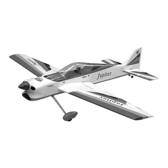
ULTRA SERIES PATTERN
Specification:
Wingspan: 1367mm (53.82 in)
Length
: 1360mm (53.54 in)
Weight
: 2600gr - 3000gr
Engine
: 46 two stroke 52 four stroke
Radio
: 4 channels / 5 servos
Advertisement

Related Manuals for Phoenix Model Jupiter Ultra Series Pattern


Summary of Contents for Phoenix Model Jupiter Ultra Series Pattern
-
Page 1: Instruction Manual
Instruction Manual ULTRA SERIES PATTERN Features: Specification: All wood construction. Wingspan: 1367mm (53.82 in) Most parts are cut by laser machine. Length : 1360mm (53.54 in) Special design for ultra - light. Weight : 2600gr - 3000gr Covered with ORACOVER. Engine : 46 two stroke 52 four stroke All accessories are included... -
Page 3: Kit Contents
KIT CONTENTS: We have organized the parts as they come out of the box for better identification during assembly. We recommend that you regroup the parts in the same manner. This will ensure you have all of parts required before you begin assembly. KIT CONTENTS MOTOR MOUNT ASSEMBLY MAIN GEAR ASSEMBLY... - Page 4 TOOLS AND SUPPLIES NEEDED. INSTALLING THE AILERON SERVOS 1. Install the rubber grommets and brass eyelets • Medium C/A glue. onto the aileron servo. • 30 minute epoxy. • 6 minute epoxy. 2. Turn the wing panel right side up. Using a •...
- Page 5 6. With the aileron and aileron servo centered, carefully place a mark on the aileron pushrod wire where it crosses the hole in the servo arm. 7. Using pliers, carefully make a 90 degree bend down at the mark made. Cut off the excess wire, leaving about 4mm beyond the bend.
- Page 6 2. Draw a center line onto the horizontal stabilizer. Draw a center line 5. Remove the stabilizer. Using the lines you just drew as a guide, carefully remove the covering from between them using a modeling knife. When cutting through the covering to remove it, cut with only enough pressure to only cut 3.
- Page 7 3. Now, remove the vertical stabilizer and using a modeling knife, carefully cut just inside the marked lines and remove the film on the top of the horizontal stabilizer. Just as you did with the horizontal stabilizer, make sure you only press hard enough to cut the film, not the balsa horizontal stabilizer.
- Page 8 1. Set the tail wheel assembly in place on the 4. Slide a 4.5mm nut/ three 16mm flat washers / plywood plate. 4.5mm nut / collar / wheel / collar onto the axle. 2. Drill 2,6mm pilot holes through the plywood 5.
- Page 9 INSTALLING THE MAIN LANDING GEAR the engine mount. Fit the engine to the engine mount using the screws provided. 1. Four nuts have been installed at the factory. 2. Install main landing gear into the fuselage using (4) 6mm x 20mm machine screws and 10mm flat washers provided in the kit.
- Page 10 To carburator To muffler To vent Tube SERVO INSTALLATION 5. Test fit the stopper assembly into the tank. It may be necessary to remove some of the INSTALLING THE FUSELAGE SERVOS flashing around the tank opening using a modeling knife. If flashing is present, make 1.
- Page 11 4. Install the clevis on the elevator pushrod. Make sure 6mm of thread shows inside the clevis. 5. The control horn should be mounted on the bottom, left side and right side of the elevator at the leading edge, in line with the elevator pushrod.
- Page 12 8. Locate one nylon servo arm, and using wire After installing the adjustable metal connector cutters, remove all but one of the arms using a apply a small drop of thin C/A to the bottom 2mm drill bit, enlarge the third hole out from the nut.
-
Page 13: Final Assembly
INSTALLING THE SPINNER 4. While holding the cowl firmly in position, drill four 1,6mm pilot holes through both the cowl and the side edges of the firewall. Install the spinner back-plate, propeller and spinner cone. The spinner cone is held in place 5. - Page 14 BALANCING CONTROL THROWS 1. We highly recommend setting up a plane using 1. It is critical that your airplane be balanced the control throws listed. correctly. Improper balance will cause your 2. The control throws should be measured at the plane to lose control and crash.
- Page 15 I/C FLIGHT WARNINGS Always operate in open areas, away Keep all onlookers (especially small from factories, hospitals, schools, THE PROPELLER IS DANGEROUS children and animals) well back from buildings and houses etc. NEVER fly Keep fingers, clothing (ties, shirt the area of operation. This is a flying your aircraft close to people or built sleeves, scarves) or any other loose aircraft, which will cause serious...
- Page 16 I/C FLIGHT GUIDELINES Operate the control sticks on the When ready to fly, first extend the transmitter and check that the control transmitter aerial. surfaces move freely and in the ALWAYS land the model INTO the CORRECT directions. wind, this ensures that the model lands at the slowest possible speed.
Need help?
Do you have a question about the Jupiter Ultra Series Pattern and is the answer not in the manual?
Questions and answers