
Related Manuals for Phoenix Model LA9


Summary of Contents for Phoenix Model LA9
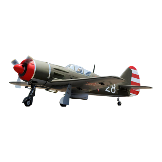
- Page 1 I n s t r u c t i o n M a n u a l Wingspan : 1820mm (71.65 inches) Length : 1625mm (63.98 inches) Weight : 6900gr Engine : 25cc - 35cc Radio : 7 channel - 9 servo, Hi-Torque ( Minimum 6 kg ).
-
Page 3: Kit Contents
Instruction Manual KIT CONTENTS: We have organized the parts as they come out of the box for better identification during assembly. We recommend that you regroup the parts in the same manner. This will ensure you have all of parts required before you begin assembly. KIT CONTENTS MAIN GEAR ASSEMBLY ELEVATOR CONTROL SYSTEM... -
Page 4: Tools And Supplies Needed
INSTALL THE AILERONS SERVOS & PUSHRODS properly before gluing! This will assure proper assembly. The LA9 size 25cc-35cc is hand made 1. Attach the servo extension to the aileron servo. from natural materials, every plane is unique and... -
Page 5: Installing The Control Horns
Instruction Manual 4. Tie the string from inside the wing to the end of the servo wire. Pull the servo wire through the wing with the string. Tape the servo wire to the wing to prevent it from falling back into the wing. -
Page 6: Installing The Aileron Linkages
Instruction Manual ↑ To the cowl 4. Repeat step # 1 - # 3 to install the control horn for the flap. Screw ↑ Flat washer Aluminum link ball To the cowl Plastic link ball Servo arm Flat washer M3 nut INSTALLING THE AILERON LINKAGES 3. -
Page 7: Installing The Landing Gear
Instruction Manual INSTALLING THE LANDING GEAR 4. Install the tube to the air retract. 1. Landing air retract. Spring 5. Remove the covering. 2. Install and secure the wheel to the gear. Collar 6. Glue the plastic part by C.A glue. 3. -
Page 8: Installing The Horizontal Stabilizer
Instruction Manual 7. Pull out the air tube through the wing section. 11.Secure the wing to the fuselage using the plastic screws. Plastic screw 8. Secure the air retract to the wing. INSTALLING THE HORIZONTAL STABILIZER 1. Remove the covering from the fuselage. Remove the covering 9. -
Page 9: Installing The Vertical Stabilizer
Instruction Manual 4. Secure the stabilizer. SERVO INSTALLATION INSTALLING THE FUSELAGE SERVOS INSTALLING THE VERTICAL STABILIZER 1. Install the rubber grommets and brass collets 1. Remove the covering from the bottom of the into the elevator, rudder and throttle servos. rudder. - Page 10 Instruction Manual Install the nylon clevis into the two elevator pushrod. Make sure 6mm of thread shows inside the clevis. 5. The control horn should be mounted on the bottom, left side and right side of the elevator. Remove the covering from the slot on the elevator.
-
Page 11: Installing The Rudder Servo
Instruction Manual INSTALLING THE RUDDER SERVO 3. Install and secure the control horn to the rudder using C.A glue. Install the rudder servo to the fuselage as shown. INSTALLING THE RUDDER LINKAGES The rudder is controlled by two metal cables. Install the rudder linkages and cables as below. -
Page 12: Installing The Tail Gear
Instruction Manual INSTALLING THE tail gear 5. Thread the metal connector to the link ball. 1. The tail gear. 2. Secure the tail gear. Screw 6. Center the rudder servo using the radio and install the servo arm. Attach the metal clevis to the rudder servo arm. -
Page 13: Installing The Engine
Instruction Manual INSTALLING THE STOPPER ASSEMBLY 1. The stopper has been pre-assembled at the factory. 2. Using a modeling knife, cut one length of silicon fuel line (the length of silicon fuel line is M3 Clevis calculated by how the weighted clunk should rest about 8mm away from the rear of the tank and move freely inside the tank). -
Page 14: Mounting The Cowl
Instruction Manual MOUNTING THE COWL Do not secure the tank into place permanently until after balancing the airplane. You may need to remove the tank to mount the battery in the 1. Measure and mark the locations to be cut out fuel tank compartment. -
Page 15: Installing The Control Air System
Instruction Manual 4. Install the air tank. Air tank INSTALLING THE CONTROL AIR SYSTEM INSTALLING THE plastic EXHAUST 1. Install the servo to the fuselage. 1. Locate and glue the plastic exhaust. 2. The air valve. 2. Secure the plastic antena. Screw 3. -
Page 16: Lateral Balance
Instruction Manual 3. Glue the plastic air scoop 2. Mount the wing to the fuselage. Using a couple of pieces of masking tape, place them on the top side of the wing 155mm back from the leading edge, at the fuselage sides. CA Glue 3. -
Page 17: Flight Preparation Pre Flight Check
Instruction Manual Low rate: FLIGHT PREPARATION PRE FLIGHT CHECK Aileron 12mm up 12mm down 1. Completely charge your transmitter and receiver Elevator 12mm up 12mm down batteries before your first day of flying. Rudder 30mm right 30mm left 2. Check every bolt and every glue joint in your Flap 15mm down plane to ensure that everything is tight and well... - Page 18 Instruction Manual I/C FLIGHT WARNINGS Always operate in open areas, away Keep all onlookers (especially small from factories, hospitals, schools, THE PROPELLER IS DANGEROUS children and animals) well back from buildings and houses etc. NEVER fly Keep fingers, clothing (ties, shirt the area of operation.
- Page 19 Instruction Manual I/C FLIGHT GUIDELINES Operate the control sticks on the When ready to fly, first extend the transmitter and check that the control transmitter aerial. surfaces move freely and in the ALWAYS land the model INTO the CORRECT directions. wind, this ensures that the model lands at the slowest possible speed.
Need help?
Do you have a question about the LA9 and is the answer not in the manual?
Questions and answers