MKS Granville-Phillips Mini-Convectron 275 series Instruction Manual
Vacuum gauge module with
linear analog output
Hide thumbs
Also See for Granville-Phillips Mini-Convectron 275 series:
- Instruction manual (68 pages) ,
- Quick start manual (2 pages) ,
- Instruction manual (50 pages)

Related Manuals for MKS Granville-Phillips Mini-Convectron 275 series


Summary of Contents for MKS Granville-Phillips Mini-Convectron 275 series
- Page 1 Series 275 ® ® Granville-Phillips Series 275 Mini-Convectron Vacuum Gauge Module with Linear Analog Output Instruction Manual Instruction Manual Instruction manual part number 275539 Revision G - November 2016...
- Page 2 Series 275 Mini-Convectron Module with both linear and non-linear analog output, no setpoint relays, and no digital display panel. 0 to 1 Torr linear analog output (0 to 10 Vdc) 1 mTorr to 1000 Torr nonlinear analog output (0.375 to 5.659 Vdc).
- Page 3 Email: mks@mksinst.com Instruction Manual © 2016 MKS Instruments. All rights reserved. Granville-Phillips ® and Convectron ® are registered trademarks, and mksinst is a trademark of MKS Instruments, Inc. All other trademarks and registered trademarks are the properties of their respective owners.
- Page 4 Catalog numbers for Series 275 Mini-Convectron Modules with Linear Analog Output (CE Marked) Includes a 9-pin D subminiature electrical connector. Operating power: 13.6 Vdc to 26.5 Vdc. The 27585X series Mini-Convectron Modules have both linear and non-linear analog output, no setpoint relays, and no digital display panel. The 275330-XX series Mini-Convectron Modules are the same as the 27585X series, and are also RoHS compliant.
-
Page 5: Table Of Contents
Table of Contents Chapter 1 Introduction/Safety ........About These Instructions . -
Page 6: Maintenance
Table of Contents 3.10 Modules Operating at Low Pressure ....Chapter 4 Maintenance ......... Customer Service . -
Page 7: Chapter 1 Introduction/Safety
Failure to comply with the instructions violates standards of design, manufacture, and intended use of the module. Granville-Phillips and MKS Instruments, Inc. disclaim all liability for the customer's failure to comply with the instructions. • Read instructions – Read all instructions before installing or operating the product. -
Page 8: Safety Instructions
Chapter 1 Safety Instructions This manual contains caution and warning statements with which you must comply to prevent inaccurate measurement, property damage, or personal injury. NOTES: These instructions do not and cannot provide for every contingency that may arise in connection with the installation, operation, or maintenance of this product. -
Page 9: Explosion / Implosion
Introduction/Safety WARNING The fumes from solvents such as trichloroethylene, perchloroethylene, toluene, and acetone can be dangerous to health if inhaled. Use only in well ventilated areas exhausted to the outdoors. Acetone and toluene are highly flammable and should not be used near an open flame or energized electrical equipment. - Page 10 Chapter 1 WARNING If accurate conversion data is not used, or is improperly used, a potential overpressure explosion hazard can be created under certain conditions. Using the N calibration to pressurize a vacuum system above about 1 Torr with certain other gases can cause dangerously high pressures which may cause explosion of the system.
-
Page 11: System Grounding
Service Guidelines Some minor problems are readily corrected on site. If the product requires service, contact the MKS, Granville-Phillips Division Technical Support Department at 1-303-652-4400 or 1-800-776-6543 for troubleshooting help over the phone. If the product must be returned to the factory for service, request a Return Material Authorization (RMA) from Granville-Phillips. -
Page 12: Specifications
Chapter 1 For Customer Service / Technical Support: MKS Pressure and Vacuum Measurement Solutions ® MKS Instruments, Inc., Granville-Phillips Division 6450 Dry Creek Parkway Longmont, Colorado 80503 USA Tel: 303-652-4400 Fax: 303-652-2844 Email: mks@mksinst.com MKS Corporate Headquarters MKS Instruments, Inc. -
Page 13: Ip Rating
Introduction/Safety Analog Outputs Bridge Output: Analog Output 0.375 to +5.659 Vdc for 0 to 1000 Torr of N , non-linear 0 to 1333 mbar of N , non-linear –1 0 to 1.33 x10 kPa of N , non-linear Linear Output: (1 Ohm output 0.0 to +10 Vdc minimum for 0 to 1000 mTorr of N impedance) - Page 14 Chapter 1 Figure 1-1 Mini-Convectron Module Physical Dimensions Table 1-2 Mini-Convectron Vacuum Connections Vacuum Connections Dim. H 1/8 NPT pipe thread, ½-inch inside diameter ® ½-inch 4 VCR type fitting, female ½-inch 8 VCR type fitting, female NW16KF flange NW25KF flange NW40KF flange ®...
-
Page 15: Chapter 2 Installation
Chapter 2 Installation The Mini-Convectron Module contains a Convectron convection-enhanced Module Components Pirani heat-loss gauge. WARNING Using the module to measure the pressure of flammable or explosive gases can cause a fire or explosion resulting in severe property damage or personal injury. Do not use the Mini−Convectron Module to measure the pressure of flammable or explosive gases. -
Page 16: Step 1 Location And Orientation Of The Module
Chapter 2 WARNING Failure to use accurate pressure conversion data for N or air to other gases can cause an explosion due to overpressurization. If the module will measure any gas other than N or air, before putting the module into operation, adjust the setpoint relays for the process gas that will be used. -
Page 17: Orientation Of The Module
Installation For proper operation of the module above 1 Torr, orient the module so the Orientation of the Module axis is horizontal (see Figure 2-1). Although the Convectron gauge will read correctly below 1 Torr with the module mounted in any position, inaccurate readings will result at pressures above 1 Torr if the module axis is not horizontal. -
Page 18: Step 2 Attach The Module To The Vacuum Chamber
Chapter 2 Step 2 Attach the Module to the Vacuum Chamber Attach the module vacuum chamber fitting to its mate on the vacuum chamber. CAUTION Twisting the module to tighten the fitting to the vacuum chamber can damage the module’s internal connections. •... -
Page 19: Conflat Flange
Installation To minimize the possibility of leaks with ConFlat flanges, use high strength ConFlat flange stainless steel bolts and a new, clean OFHC copper gasket. Avoid scratching the seal surfaces. To avoid contamination, install metal gaskets. a. Finger tighten all bolts. b. -
Page 20: Grounding
Chapter 2 Grounding WARNING Improper grounding could cause product failure, property damage, or serious personal injury. To reduce the risk of product failure, property damage, or serious personal injury, follow ground network requirements for the facility. • Maintain all exposed conductors at earth ground. •... -
Page 21: Step 4
Installation WARNING Failure to use accurate pressure conversion data for N or air to other gases can cause an explosion due to overpressurization. Step 4 Calibrate the Convectron Gauge Calibration improves the accuracy and repeatability of the Convectron gauge. An atmospheric calibration is performed on the Convectron gauge, using N , at the factory before the module is shipped. -
Page 22: Calibrate At Vacuum Chamber Pressure
Chapter 2 Table 2-1 Typical Altitude/Torr/Bridge Voltage Relationships Analog Output Altitude Above Sea Level Pressure of N or Air Voltage Feet Meters Torr mbar (Vdc) 1013 5.534 1000 5.513 2000 5.493 3000 5.473 4000 1219 5.454 5000 1524 5.435 6000 1829 5.417 7000... -
Page 23: Set The Full Scale Adjustment
Installation The FULL SCALE adjustment calibrates the linear analog output voltage for Set the FULL SCALE Adjustment the specific gas-type being used in the vacuum chamber. There are 2 methods to set the FULL SCALE adjustment. 1. Use another gauge that is gas-independent and known to be accurate: a. - Page 24 Chapter 2 Notes Mini-Convectron Module Instruction Manual - 275539...
-
Page 25: Chapter 3 Operation
Chapter 3 Operation This chapter explains how to operate the Mini-Convectron Module with a linear analog output. Calibrating the Convectron Gauge, and using the Convectron Gauge with gases other than N or Air are explained. –4 The module measures gas pressures from 1 x 10 Torr to 1000 Torr. -
Page 26: Front Panel Features
Chapter 3 As vacuum chamber pressure decreases, the number of molecules in the vacuum chamber and the resulting heat loss from the sensing wire also decrease. Temperature and R resistance therefore increase. The increased resistance through R causes the bridge to become unbalanced and a voltage to develop across the null terminals. -
Page 27: Preparing For Operation
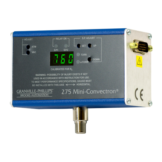
Operation Figure 3-2 Mini-Convectron Module Front Panel - Indicator and Adjustments Before putting the module into operation, you must perform the following Preparing for Operation procedures: Install the module in accordance with the instructions on pages 15-23. Develop a logic diagram of the process control function. Attach a copy of the process control circuit diagram to this manual for future reference and troubleshooting. -
Page 28: Understanding Convectron Gauge Pressure Measurement In Gases Other Than Nitrogen Or Air
Chapter 3 type, gas density (pressure), and the module orientation. The module is factory calibrated for N (air has approximately the same calibration). For gases other than N or air, heat loss varies at any given pressure, and you must apply an appropriate conversion factor. Convectron Gauges are Pirani type thermal conductivity gauges that Understanding Convectron Gauge... -
Page 29: Commonly Used Gases Other Than N Or Air
Operation NOTE: You must ensure that the atmosphere adjustments for the Mini-Convectron Module are correctly set. See Calibrate at Atmosphere on page 21. If the gas being used is not included in Table 3-2, or for a gas mixture, you Commonly used Gases Other than N or Air... - Page 30 Chapter 3 Table 3-1 Equations for Calculating N or Air Pressure versus Bridge Analog Output Voltage Segment Output Voltage Equation where y = Pressure and x = Voltage Coefficients 0.375 to 2.842 V –0.02585 Torr 0.03767 ) 133.3 × 0.04563 0.1151 ×...
- Page 31 Operation Table 3-2 Bridge Analog Output Voltage (Vdc) for Various Gases Mini-Convectron Module Instruction Manual - 275539...
-
Page 32: Bridge Analog Output Voltage
Chapter 3 Figure 3-5 and Figure 3-6 illustrate the relationship of true pressure as Bridge Analog Output Voltage bridge analog output voltage (Vdc) when using N or Air in the vacuum system. The graphs are plotted using the data in Table 3-2, which lists the bridge analog output voltage at various pressures, using various gases. -
Page 33: External Calibration
Operation It is possible to accomplish a full scale calibration of the linear analog External Calibration output externally to the Mini-Convectron Module for use in a system where multiple gases are being switched. By varying the feedback resistor of the final amplifier from a nominal of 10 K Ohm, you can compensate for the approximate resistance value shown in Table 3-3. - Page 34 Chapter 3 NOTE: To use the external calibration technique, a jumper inside of the Mini-Convectron Module must be removed. To remove the internal jumper: Turn OFF power to the Mini-Convectron Module and unplug the 9-pin connector on the side of the module. Remove the 4 screws on each side of the module but not the two D-connector hex head jack screws.
-
Page 35: Or Air Pressure
Operation Figure 3-5 Analog Output Voltage vs. Indicated N or Air Pressure, 1 mTorr to 100 mTorr Mini-Convectron Module Instruction Manual - 275539... - Page 36 Chapter 3 Figure 3-6 Analog Output Voltage vs. Indicated N or Air Pressure, 0.1 Torr to 1000 Torr Mini-Convectron Module Instruction Manual - 275539...
- Page 37 Operation Figure 3-7 Linear Analog Output Voltage (Vdc) for Various Gases Mini-Convectron Module Instruction Manual - 275539...
-
Page 38: True Pressure Versus Indicated Pressure
Chapter 3 –4 –1 Figure 3-8 True Pressure versus Indicated Pressure for Commonly used Gases, 10 to 10 Torr , Air freon 22 freon 12 Use this data only when the Convectron Gauge axis is horizontal. Do NOT use this data with any transducers other than G-P Series 275 Convectron Gauges. - Page 39 Operation –1 Figure 3-9 True Pressure versus Indicated Pressure for Commonly used Gases, 10 to 1000 Torr 1000 freon 12 N , air Use this data only when the Convectron Gauge axis is horizontal. Do NOT use this data with any transducers other than G-P Series 275 Convectron Gauges.
- Page 40 Chapter 3 –1 Figure 3-10 True Pressure versus Indicated Pressure for Commonly used Gases, 10 to 1000 Torr 1000 freon 22 N , air Use this data only when the Convectron Gauge axis is horizontal. Do NOT use this data with any transducers other than G-P Series 275 Convectron Gauges.
- Page 41 Operation –4 Figure 3-11 True Pressure versus Indicated Pressure for Commonly used Gases, 10 to 0.1 mbar , Air freon 22 freon 12 Use this data only when the Convectron Gauge axis is horizontal. Do NOT use this data with any transducers other than G-P Series 275 Convectron Gauges.
- Page 42 Chapter 3 Figure 3-12 True Pressure versus Indicated Pressure for Commonly used Gases, 0.10 to 1000 mbar 1000 freon 12 N , air Use this data only when the Convectron Gauge axis is horizontal. Do NOT use this data with any transducers other than G-P Series 275 Convectron Gauges.
- Page 43 Operation Figure 3-13 True Pressure versus Indicated Pressure for Commonly used Gases, 0.10 to 1000 mbar 1000 freon 22 N , air Use this data only when the Convectron Gauge axis is horizontal. Do NOT use this data with any transducers other than G-P Series 275 Convectron Gauges.
-
Page 44: Modules Operating At Low Pressure
Chapter 3 During a fast pumpdown from atmospheric pressure, thermal effects 3.10 Modules Operating at Low Pressure temporarily prevent the module from measuring pressure accurately below 1 x 10 –3 Torr (1.3 x 10 –4 kPa, 1.3 x 10 –3 mbar). -
Page 45: Chapter 4 Maintenance
Chapter 4 Maintenance For Customer Service / Technical Support: Customer Service MKS Pressure and Vacuum Measurement Solutions ® MKS Instruments, Inc., Granville-Phillips Division 6450 Dry Creek Parkway Longmont, Colorado 80503 USA Tel: 303-652-4400 Fax: 303-652-2844 Email: mks@mksinst.com Turn OFF power to the module and refer servicing to qualified service... -
Page 46: Troubleshooting
Chapter 4 If any of the conditions described on page 45 have occurred, Troubleshooting troubleshooting is required to determine the repairs that are necessary. Because the Convectron gauge contains static-sensitive electronic parts, Precautions follow these precautions while troubleshooting: • Use a grounded, conductive work surface. Wear a high impedance ground strap for personal protection. -
Page 47: Symptoms, Causes, And Solutions
Maintenance Table 4-1 lists failure symptoms, causes, and solutions. Symptoms, Causes, and Solutions Table 4-1 Failure Symptoms, Causes, and Solutions Symptom Possible Causes Solution Output voltage = 0 V 13.6 to 26.5 Vdc power supply cable is Repair or replace power supply cable improperly connected or faulty. -
Page 48: Convectron Gauge Test
Chapter 4 Convectron Gauge Test CAUTION Do not perform a Convectron gauge test with an instrument that applies more than 0.1 V of electromotive force. Performing a Convectron gauge test with instruments that apply more than 0.1 V with the gauge at vacuum chamber pressure can result in property damage. -
Page 49: Convectron Gauge Removal And Replacement
Maintenance Convectron Gauge Removal and WARNING Replacement Removing or replacing the Convectron gauge in a high−voltage environment can cause an electrical discharge through a gas or plasma, resulting in serious property damage or personal injury due to electrical shock. Vent the vacuum chamber to atmospheric pressure and shut off power to the module before you remove or replace the Convectron gauge. -
Page 50: Returning A Product For Repair
Some minor problems are readily corrected on site. If the product requires Returning a Product for Repair service, contact the MKS, Granville-Phillips Division Technical Support Department at 1-303-652-4400 or 1-800-776-6543 for troubleshooting help over the phone. If the product must be returned to the factory for service, request a Return Material Authorization (RMA) from Granville-Phillips. -
Page 51: Index
Index ground connection to vacuum chamber 20 Module Orientation 17 Analog Output module with two relays, no display 14, 27 Equations 30 output voltage versus N or air pressure Voltage/Pressure 29, 31 0.1 Torr to 1000 Torr 36 Wiring 19 true pressure versus indicated pressure Atmosphere Adjustment 26 to 10... -
Page 52: Mini-Convectron Module Instruction Manual
Index Convectron gauge removal 49 Convectron Gauge Replacement 49 Reading and Following Instructions 7 Convectron Gauge Test 48 Relief Devices 15 Customer Service 45 Returning a Damaged Module 50 Damage Requiring Service 45 Failure Symptoms, Causes, and Solutions 47 Returning a Damaged Module 50 Safety Instructions 8 Troubleshooting 46 Service Guidelines 11... - Page 53 Index Wiring Analog Output 19 Connecting Cable 19 Grounding 20 I/O Connector Specifications 12 I/O connector module with two relays 19 Installation 19 Power Supply 19 Terminals 19 Zero Adjustment 26 Mini-Convectron Module Instruction Manual - 275539...
- Page 54 Index Mini-Convectron Module Instruction Manual - 275539...
-
Page 56: Customer Service
® Granville-Phillips Series 275 Mini-Convectron Vacuum Gauge Module with Linear Analog Output Customer Service / Technical Support: MKS Pressure and Vacuum Measurement Solutions MKS Instruments, Inc., Granville-Phillips® Division 6450 Dry Creek Parkway Longmont, Colorado 80503 U.S.A. Tel: 303-652-4400 Fax: 303-652-2844 Email: mks@mksinst.com...
Need help?
Do you have a question about the Granville-Phillips Mini-Convectron 275 series and is the answer not in the manual?
Questions and answers