Table of Contents
Advertisement
Advertisement
Table of Contents

Related Manuals for MKS Vision 2000-C


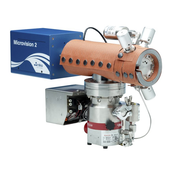
Summary of Contents for MKS Vision 2000-C
- Page 1 Vision 2000-C/E Manual SP102005.102 March 2013...
- Page 2 +44 (0) 1270 250150 Tel. +44 (0) 1270 251939 Fax. www.mksinst.com MKS Products provided subject to the US Export Regulations. Diversion or transfer contrary to U.S. law is prohibited. Windows is a registered trademark of the Microsoft Corporation and is fully recognised.
- Page 3 MKS Instruments UK Ltd V2000-C/E Hardware Manual – SP102005.102 March 2013...
- Page 4 MKS Instruments UK Ltd V2000-C/E Hardware Manual – SP102005.102 March 2013...
-
Page 5: Additional Installation Maintenance And Operating Instructions
Cables attached to all other ancillary signal and control ports must have a length of less than 3 metres. If greater length is required, MKS Instruments UK Ltd must be contacted for technical guidance on possible EMC and safety issues. -
Page 7: Table Of Contents
Mass spec maintenance ..............................32 Removing the analyser ..............................34 Re-fitting the analyser ..............................34 ..............................35 ETURNING QUIPMENT Support Contact Numbers ..............................35 Health and safety clearance form ............................ 35 MKS Instruments UK Ltd V2000-C/E Hardware Manual – SP102005.102 March 2013... -
Page 8: Health & Safety
Instructions in CAUTION and WARNING boxes MUST be observed. MKS Instruments accepts no liability for any injury or damage resulting from a failure to observe instructions in CAUTION or WARNING boxes. -
Page 9: Warning Symbols
This is generally used on the instruments to warn of the presence of hazardous voltages. The following warning labels used on the Vision 2000-C/E systems are explained below. The Exclamation Mark (ISO 3864, No.B.3.1) label. On the rear panel of the Microvision2 refers to: Read all instructions carefully before use. -
Page 10: Fuses
Details of fuse types and ratings can be found in the RVC2 manual and printed on the rear panel. Electrical Connections The Vision 2000-C/E must be powered down and isolated from the mains power supply before any electrical connections are made. -
Page 11: Installation
There are small differences among Vision 2000-C/E systems. Variations are usually due to the type of process tool to which the Vision 2000-C/E is to be fitted, the type of process to be monitored and the pressure regime from which the system will be sampling. -
Page 12: System Options
System Options Fig.1: 3-Valve “Etch” Configuration Fig.2: 4-Valve, Fast-Response “LPCVD” Configuration Fig.3: 4-Valve, High-Pressure “CVD” Configuration MKS Instruments UK Ltd V2000-C/E Hardware Manual – SP102005.102 March 2013... -
Page 13: Unpacking
MKS Instruments facility or sales/service representative. Carefully unpack the various parts of your Vision 2000-C/E system. Again, check for any signs of damage. Find the shipment report and check for any missing items. Keep the shipment report safe, this is an important document and you may need to refer to it later. -
Page 14: Vacuum System Installation
Vacuum System installation As much of the system as possible has been shipped pre-assembled. The whole of your Vision 2000-C/E system has been assembled and tested before being partially dissembled prior to shipping. CAUTION The vacuum system interface components are of high precision and should only be fitted by competent personnel. - Page 15 Dimensions 490mm 225mm 265mm 340mm 166mm MKS Instruments UK Ltd V2000-C/E Hardware Manual – SP102005.102 March 2013...
- Page 16 Purge regulator assembly – 3.5 to 8Bar Argon or dry Nitrogen supply required ** System Interface Module Turbo molecular pump and controller ** The Purge supply regulator is factory set and requires no adjustment. MKS Instruments UK Ltd V2000-C/E Hardware Manual – SP102005.102 March 2013...
- Page 17 Pneumatics supply Use adaptor if required Surge Protect supply Item Ref Description Pneumatic Manifold assembly – 60 – 80 psig dry air Fore line connecting flange Cable loom supporting bracket MKS Instruments UK Ltd V2000-C/E Hardware Manual – SP102005.102 March 2013...
- Page 18 Item Ref Description UniBloc ™ mounting face MKS Instruments UK Ltd V2000-C/E Hardware Manual – SP102005.102 March 2013...
-
Page 19: Main Chamber Installation
Most process tools have aluminium chamber walls with fittings that will not support this weight and torque, directly. MKS Spectra Products offers an adjustable stand to support the weight of the RGA at the tool without stressing the point of vacuum connection (e.g., model 02184-4175). Please contact your MKS Spectra representative for details on available sizes and configurations. -
Page 20: Heater Jackets
The last 3mm (1/8”) is important. When correctly fitted the front face of the RF/analyser connector should butt up against the analyser flange. Finally, tighten the clamping ring enough to securely hold the Microvision2 to the analyser. MKS Instruments UK Ltd V2000-C/E Hardware Manual – SP102005.102 March 2013... -
Page 21: Electrical Installation
Only use IEC or UL approved Mains fuses are used to protect this equipment: Safety Class I Installation Category II Pollution Category II WARNING This appliance must be earthed MKS Instruments UK Ltd V2000-C/E Hardware Manual – SP102005.102 March 2013... -
Page 22: Equipment Rack
Interface Module - System 2 System 3 System Box Interface Module - System 2 Turbo Pump Turbo Pump Turbo pump control module ECU Power Power Microvision2 Digital IO Digital IO Microvision2 MKS Instruments UK Ltd V2000-C/E Hardware Manual – SP102005.102 March 2013... -
Page 23: Connecting To The Process Tool
GREEN/YELLOW Computer connection Vision 2000C/E systems are used in conjunction with MKS Instruments Process Eye Professional software running on a PC. If a PC has been supplied as part of the system, the software will have been installed onto the hard drive and will have been fully tested as part of the complete Vision 2000C/E system. -
Page 25: Operation
These set-points are factory preset for the inlet supplied. A process valve can be opened either manually or automatically from the Process Eye Professional software interface to the RVC2. MKS Instruments UK Ltd V2000-C/E Hardware Manual – SP102005.102 March 2013... -
Page 26: Start Up
Once you have established that the process valve is working correctly, close the valve. Minimizing exposure to corrosive process gases when not actively monitoring them will protect RGA system operating life. MKS Instruments UK Ltd V2000-C/E Hardware Manual – SP102005.102 March 2013... -
Page 27: Leak Checking
Remember you may need to break the seal between the Vision 2000C/E and the process chamber in which case you will also have to shut down the process chamber. MKS Instruments UK Ltd V2000-C/E Hardware Manual – SP102005.102 March 2013... -
Page 28: Heating And Baking
Warning, exposed metal surfaces reach high temperatures during bake-out. Allow an adequate cooling down period before handling MKS Instruments UK Ltd V2000-C/E Hardware Manual – SP102005.102 March 2013... -
Page 29: Inlet Operation
Switch off the turbo pump from the RVC2 Window within Process Eye Professional, or by pressing the PUMPS switch on the RVC2. Switch off the RVC2. Allow the turbopump to come to a complete stop MKS Instruments UK Ltd V2000-C/E Hardware Manual – SP102005.102 March 2013... -
Page 31: Maintenance
If the process chamber is vented frequently, or ambient temperature changes. In general, it is a good idea to schedule maintenance of the Vision 2000-C/E, including preventative measures, such as renewing filaments, to coincide with planned maintenance of the process system. -
Page 32: Removing The Inlet Valve Assembly
No damage will be caused to the analyser or the electronics if a replacement standard RGA control unit is fitted, but the performance will be dramatically reduced. This is of particular relevance to customers who operate more than one MKS RGA. Turbo pump maintenance The bearings in the turbo pump need to be re-lubricated, periodically. - Page 33 The safest place for the analyser is in its vacuum chamber, so leave the analyser where it is until you have everything ready. MKS Instruments UK Ltd V2000-C/E Hardware Manual – SP102005.102 March 2013...
-
Page 34: Removing The Analyser
Rotate the analyser flange so that it is in the correct orientation, as noted in the above steps. Bolt the flanges together remembering to tighten opposite bolts equally. Re-fit the Microvision2. MKS Instruments UK Ltd V2000-C/E Hardware Manual – SP102005.102 March 2013... -
Page 35: Returning Your Equipment
If you wish to return your instrument for service, please follow these simple guidelines: Contact your local MKS service facility to obtain a Returns Material Authorisation (RMA) number. We will require some instrument details, such as the serial numbers, date of purchase and a fault description. - Page 36 Customer Return To Address (if different from above): Company Department Address City Zip/Postal Code User’s Name: Phone No.: Equipment Shipped Item 1: Serial No.: Item 2: Serial No.: Item 3: Serial No.: MKS Instruments UK Ltd V2000-C/E Hardware Manual – SP102005.102 March 2013...
- Page 37 1. The equipment has been securely packaged and labelled. 2. The carrier has been informed of the hazardous nature of the consignment. Signed: Title: Date: Phone No.: MKS Instruments UK Ltd V2000-C/E Hardware Manual – SP102005.102 March 2013...
Need help?
Do you have a question about the Vision 2000-C and is the answer not in the manual?
Questions and answers