
Related Manuals for MKS Microvision2


Summary of Contents for MKS Microvision2
- Page 1 Microvision2 Hardware Manual Microvision2 Hardware Manual - SP101015.102 August 2010...
- Page 2 +44 (0)1270 250150 Tel. International +44 (0)1270 251939 Fax. International Email: manual_info@mksinst.com Microvision2 is a registered trademark of MKS Instruments UK Limited. Conflat® is a registered trademark of Varian Associates. Viton® is a registered trademark of E.I. DuPont de Nemours & Co., Inc.
-
Page 3: Table Of Contents
7. Connecting to the Ethernet Port 21 24VDC Power Supply 6 Analyser 6 7.1 Adding the Microvision2 22 1.2 Electrical 6 7.2 Directly connecting to the Microvision2 23 1.2 Electrical 7 7.3 Assigning a static IP Address 26 Power Supply 7 8. Baking 28 1.3 Environmental 7... - Page 4 I hereby declare that the equipment named above has been designed to comply with the relevant sections of the above referenced specifications. The unit complies with all essential requirements of the Directives. Signed: J.M.Higgins General Manager October 2009 MKS Instruments UK Ltd Microvision2 Hardware Manual – SP101015.102 August 2010...
-
Page 5: Overview
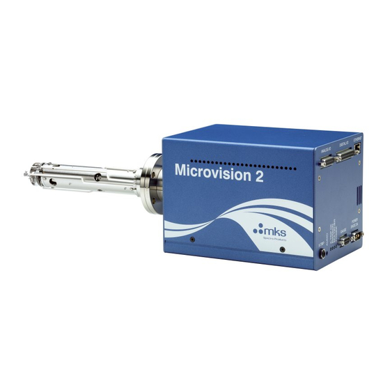
Overview The Microvision2 is the latest innovation in RGA technology from MKS Instruments. Designed to meet all the traditional requirements for an RGA sensor, plus data collection speeds in the milliseconds, even over the full dynamic range - unachievable with previous technologies. -
Page 6: Specifications
1.7 kg 24VDC Power Supply Dimensions: 75mm wide x 45mm high x 146mm deep plus 30mm over strain relief. Weight: 0.6 kg Analyser Max. Operating pressure 7.6x10 (1x10 mbar) MKS Instruments UK Ltd Microvision2 Hardware Manual – SP101015.102 August 2010... -
Page 7: Electrical
The protective earth conductor of the power cord must be connected to the power source protective earth terminal. There are no operator replaceable parts within the 24VDC power supply unit or the Microvision2 unit. 1.5 Connectors The connectors for external circuits are for use only with MKS equipment, or equipment which has no accessible hazardous live parts. -
Page 8: Warning Labels
On the rear panel refers to: a. Read all instructions carefully before use. b. The control unit and signal ports are designed for connection to MKS accessories via MKS supplied cables. There are no accessible hazardous voltages or currents on these ports. - Page 9 5. Cables attached to all other ancillary signal and control ports must have a length of less than 3 meters. If greater length is required, MKS Instruments Ltd. must be contacted for technical guidance on possible EMC and safety issues.
- Page 10 3. There are no user serviceable parts in the electronic equipment. Certain components are EMC and safety critical and must not be substituted. Replacement parts are available from MKS Instruments UK Ltd. 4. Equipment enclosures embody certain special fastenings and bonding devices that affect EMC and safety performance.
-
Page 11: Rear Panel Connections
The X-Trip connector requires a special locking, stereo jack plug, which is supplied with the unit. Do not use a standard 3.5mm jack plug. Replacements are available from MKS Instruments if required. The external trip feature is used to protect the filaments and electron multiplier from exposure to high pressures. -
Page 12: Audio Socket
The indicator is lit when power is supplied to the multiplier detector (if fitted). 4.5 Power Indicator The indicator is lit when power is supplied to the Microvision2 unit. MKS Instruments UK Ltd Microvision2 Hardware Manual – SP101015.102 August 2010... -
Page 13: Gauge Connector
Differential Signal Input Low Gauge pressure output Gauge Enable Open collector to gauge 4.7 Power A 2-pin D-type connecter used to for the 24VDC power supply. Function Description 24VDC MKS Instruments UK Ltd Microvision2 Hardware Manual – SP101015.102 August 2010... -
Page 14: Analogue I/O Connector
Analogue Output 1 0 – 10v Analogue Output 2 0 – 10v NOTE: The 120mA maximum load for the power supply outputs is shared between the Digital and Analogue connectors. MKS Instruments UK Ltd Microvision2 Hardware Manual – SP101015.102 August 2010... -
Page 15: Digital I/O Connector
-15V supply output, fused at 120mA +15V +15V supply output, fused at 120mA +3.3V fused +3.3V supply output, fused at 120mA Not Connected +24V +24V supply output, fused at 120mA MKS Instruments UK Ltd Microvision2 Hardware Manual – SP101015.102 August 2010... -
Page 16: Ethernet
Using this approach allows for easily interfacing between different voltage levels and logic families. 4.10 Ethernet A standard RJ45 type 10/100 Base-T Ethernet connector used to connect the Microvision2 to a host PC, hub, switch or network. Ensure you read through the network scenarios starting on Page 21 before connecting the unit to your network 4.11 External Multiplier Protection... -
Page 17: Analyser Installation
5.1 Unpacking When you receive the Microvision2 carefully check each item before removing the foam packaging and plastic wrapping, to ensure that no physical damage has occurred during shipment. Also, make sure all items have been received correctly by checking each item against the enclosed packing slip. -
Page 18: Installing The Analyser
There must be at least the distances stated free of obstructions inside the vacuum chamber. If your chamber does not meet the above criteria, you should use a specially designed adapter so that the analyser may be mounted outside the chamber. Please contact your local MKS representative for assistance. -
Page 19: Mounting The Analyser
Rotate the flange until the locating key on the feedthrough housing tube is as close to 9 o'clock as the bolt holes will allow. This will ensure that the Microvision2 is in its preferred position, although it can be mounted in any orientation. -
Page 20: Microvision2 Installation
Rotate the locking ring on the stainless steel analyser connector so that the slot lines up with the keyway on the connector tube. Hold the Microvision2 unit so that the keyway lines up with the locating key on the analyser flange and gently slide the Microvision2 unit on to the analyser. -
Page 21: Connecting To The Ethernet Port
Each address is issued manually to each device by the network administrator. By default the Microvision2 is configured for Auto-IP which is by far the simplest method if you are new to networking, or are installing the Microvision2 into an existing Auto-IP or DHCP network. -
Page 22: Adding The Microvision2
See the Static IP Addressing section For details on how to assign a static IP address to the Microvision2, please see the guide on Page 26. You will need to be allocated an IP address for use by your IT Specialist, or have them perform the installation for you. -
Page 23: Directly Connecting To The Microvision2
7.2 Directly connecting to the Microvision2 If your PC or MAC is not part of a network, you may choose to connect the Microvision2 directly to the Ethernet port or a local hub. The following section describes what is required to get your unit up and running. - Page 24 While the PC or MAC has been generating its automatic IP address, the Microvision2 will be attempting to generate a compatible address. You may need to wait 30 seconds after the PC or MAC has an IP address before the Microvision2 is ready. MKS Instruments UK Ltd...
- Page 25 You can check the status of the Microvision2 by using the RGA Device Manager application on the supplied MKS Utilities CD. Double-click the RGA Device Manager icon to start the application. After a few moments the following dialog appears displaying a list of all discovered MKS RGA’s.
-
Page 26: Assigning A Static Ip Address
192.168.0.1. When the Microvision2 is connected to the network, it will “ask” to be assigned an IP address from a DHCP server, as one will not be present in this type of network, the Microvision2 will use a default address in the range 169.254.xxx.xxx. - Page 27 Right-click the instrument and select “Change IP Address”. You can see that the Microvision2 is configured to receive an IP address. We must change this option to continue. Select the “Use the following fixed settings” option. Enter the IP address and the Subnet issued to you by your IT Specialist.
-
Page 28: Baking
8. Baking The Microvision2 electronics package must not be exposed to ambient temperatures above 40 C. If the analyser flange temperature exceeds 200 C the Microvision2 or Thermal Extender must be removed. If baking at the maximum temperature of 200 C for 8 hours, the Microvision2 can remain attached to the analyser, if baking for longer periods then a Thermal Extender must be used. -
Page 29: Analyser Maintenance
2000 deg K at which temperature it emits electrons, which are used to produce the ions required by the quadrupole filter. At this high temperature, there are two deleterious effects; MKS Instruments UK Ltd Microvision2 Hardware Manual – SP101015.102 August 2010... -
Page 30: Ohmmeter Analyser Checks
In either case, remove the analyser from the vacuum chamber and repeat the test. If the result is the same, then you have an internal short and should contact your local MKS facility for advice. Otherwise, you have a short to the vacuum chamber, check the dimensions of the vacuum chamber around the quadrupole analyser against the dimensions provided on Page 6 of this manual, or try refitting the analyser in a slightly different orientation. -
Page 31: Checking Filaments
All the pins should show an open circuit to all other pins, EXCEPT pin 4 to 8 and pin 8 to 10, which should show short-circuit as these are the filament connections. If any of the pins read short-circuit to another pin, contact your local MKS service center with the results of your tests and they will advise you how to proceed. -
Page 32: Changing Filaments
Changing filaments is the most common maintenance event with quadrupole analysers. For this reason the MKS analyser has been designed to make this task as quick and easy as possible. Below is a list of the tools and equipment you will require. We recommend that you assemble the following items before you start. - Page 33 If these oxides are present, it is recommended that you refer to the section on ion source cleaning on page 38 before proceeding. MKS Instruments UK Ltd Microvision2 Hardware Manual – SP101015.102 August 2010...
-
Page 34: Fitting Filaments
5. Replace the analyser into your vacuum housing and again check for shorts or grounding to the outer vacuum housing. You are now ready to pump down and continue the operation of your quadrupole. MKS Instruments UK Ltd Microvision2 Hardware Manual – SP101015.102 August 2010... -
Page 35: Removing The Filaments
Remove the four M2 x4 pan head screws highlighted in red holding the filament plate in place, see Fig.3. Remove the two filament plates. Carry out this step carefully so as not to damage the filaments, see Fig.4. Refer to the views on the following page. MKS Instruments UK Ltd Microvision2 Hardware Manual – SP101015.102 August 2010... - Page 36 If these oxides are present, it is recommended that you refer to the section on ion source cleaning on page 38 before proceeding. MKS Instruments UK Ltd Microvision2 Hardware Manual – SP101015.102 August 2010...
-
Page 37: Fitting Filaments
5. Replace the analyser into your vacuum housing and again check for shorts or grounding to the outer vacuum housing. You are now ready to pump down and continue the operation of your quadrupole. MKS Instruments UK Ltd Microvision2 Hardware Manual – SP101015.102 August 2010... -
Page 38: Ion Source Cleaning
After the bake period, check all the screws in the ion source are tight and re-fit the analyser to the vacuum chamber. A further bake under vacuum will be required to drive off any remaining residue. MKS Instruments UK Ltd Microvision2 Hardware Manual – SP101015.102 August 2010... -
Page 39: Removing To Clean Or Replace
5. Remove the four M2 x4 screws and shakeproof washers highlighted in red that hold the source assembly to the filter assembly, see Fig.3. 6. Carefully withdraw the source assembly from the filter, Fig.4. Refer to the views on the following page. MKS Instruments UK Ltd Microvision2 Hardware Manual – SP101015.102 August 2010... - Page 40 Open Ion source Fig.2 Fig.1 Fig.3 Fig.4 MKS Instruments UK Ltd Microvision2 Hardware Manual – SP101015.102 August 2010...
-
Page 41: Refitting The Open Ion Source
Once positioned, slide home the ion-source assembly so that it sits flush on top of the filter, refit the four M2x4 screws plus shakeproof washers and tighten securely. MKS Instruments UK Ltd Microvision2 Hardware Manual – SP101015.102 August 2010... -
Page 42: Removing To Clean Or Replace
5. Remove the three M2 x4 screws and shakeproof washers highlighted in red that hold the source assembly to the filter assembly, see Fig.3. 6. Carefully withdraw the source assembly from the filter, Fig.4. Refer to the views on the following page. MKS Instruments UK Ltd Microvision2 Hardware Manual – SP101015.102 August 2010... - Page 43 PVD / CVD Ion source Fig.1 Fig.2 Fig.2a MKS Instruments UK Ltd Microvision2 Hardware Manual – SP101015.102 August 2010...
-
Page 44: Refitting The Pvd / Cvd Ion Source
Once positioned, slide home the ion-source assembly so that it sits flush on top of the filter, refit the three M2x4 screws and shakeproof washers and tighten securely. MKS Instruments UK Ltd Microvision2 Hardware Manual – SP101015.102 August 2010... -
Page 45: Analyser Pin-Outs
Pin Descriptions Connection Earth Source plate Electron Multiplier Filament 1 Extraction plate Suppressor plate RF.1 Repeller plate / filament common No connection Filament 2 RF.2 Collector MKS Instruments UK Ltd Microvision2 Hardware Manual – SP101015.102 August 2010... -
Page 46: Spare Parts
842-047 Any filter type 842-052 842-053 If you require a spare part not mentioned above, please contact your local MKS Instruments office for help on obtaining a part number. MKS Instruments UK Ltd Microvision2 Hardware Manual – SP101015.102 August 2010... -
Page 47: Support Contact Numbers
If you wish to return your instrument for service, please follow these simple guidelines. Contact your local MKS service facility to obtain a Returns Material Authorisation (RMA) number. We will require some instrument details, such as the serial numbers, date of purchase and a fault description. - Page 48 MKS Instruments UK Ltd Microvision2 Hardware Manual – SP101015.102 August 2010...
- Page 49 RETURNS FORM Please complete the form and send to the appropriate MKS facility. Please ensure that we have this information before we receive the equipment. A copy should also be given to the carrier. FAILURE TO COMPLETE THIS FORM OR COMPLY WITH THE...
- Page 50 1. The equipment has been securely packaged and labelled. 2. The carrier has been informed of the hazardous nature of the consignment if applicable. Signed: Title: Date: Phone No.: MKS Instruments UK Ltd Microvision2 Hardware Manual – SP101015.102 August 2010...
Need help?
Do you have a question about the Microvision2 and is the answer not in the manual?
Questions and answers