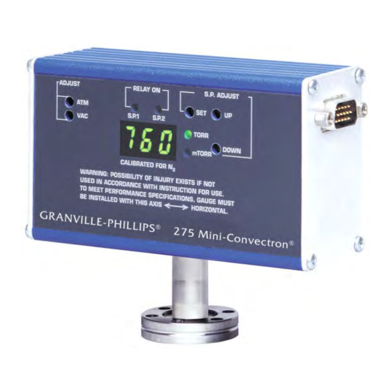
MKS Granville-Phillips Series 275 Instruction Manual
Mini-convectron vacuum gauge module
with nonlinear analog outputs and process
control relays
Hide thumbs
Also See for Granville-Phillips Series 275:
- Quick start manual (2 pages) ,
- Instruction manual (52 pages) ,
- Instruction manual (55 pages)

Related Manuals for MKS Granville-Phillips Series 275


Summary of Contents for MKS Granville-Phillips Series 275
- Page 1 Series 275 ® Granville-Phillips Series 275 ® Mini-Convectron Vacuum Gauge Module with Nonlinear Analog Outputs and Process Control Relays Instruction Manual Instruction manual part number 275512 Revision D - November 2016...
- Page 3 Instruction Manual © 2016 MKS Instruments, Inc. All rights reserved. Granville-Phillips ® and Convectron ® are registered trademarks, and mksinst is a trademark of MKS Instruments, Inc. All other trademarks and registered trademarks are the properties of their respective owners.
- Page 4 Catalog numbers for Series 275 Mini-Convectron Modules (CE Marked) With electrical connector. Operating power: 11.5 Vdc to 26.5 Vdc Mini-Convectron Module with one (1) setpoint relay 1/8 NPT / 1/2 inch tubulation 275800-EU 1/4 inch VCR-type female fitting 275801-EU 1/2 inch VCR-type female fitting 275863-EU 3/8 inch VCO-type male fitting 275802-EU...
- Page 5 Catalog numbers (Continued) Catalog numbers for Series 275 Mini-Convectron Modules (CE Marked) With electrical connector. Operating power: 11.5 Vdc to 26.5 Vdc Mini-Convectron Module with two (2)setpoint relays and 3-digit digital display Display in Pascal 1/8 NPT / 1/2 inch tubulation 275904-EU-P 1/4 inch VCR-type female fitting 275905-EU-P...
- Page 6 Notes:...
-
Page 7: Table Of Contents
Table of Contents Chapter 1 Before You Begin ........About These Instructions . - Page 8 Table of Contents Chapter 4 Maintenance ......... Customer Service .
-
Page 9: Before You Begin
The Convectron convection-enhanced Pirani heat-loss gauge, which measures pressure within the vacuum chamber Customer Service / Technical Support: Customer Service MKS Pressure and Vacuum Measurement Solutions MKS Instruments, Inc., Granville-Phillips® Division 6450 Dry Creek Parkway Longmont, Colorado 80503 U.S.A. Tel: 303-652-4400 Fax: 303-652-2844 Email: mks@mksinst.com... -
Page 10: Caution And Warning Statements
Chapter 1 This manual contains caution and warning statements with which you must Caution and Warning Statements comply to prevent inaccurate measurement, property damage, or personal injury. CAUTION Caution statements alert you to hazards or unsafe practices that could result in minor personal injury or property damage. -
Page 11: Implosion / Explosion
Before You Begin Ion producing equipment, such as ionization gauges, mass spectrometers, sputtering systems, etc., from many manufacturers may, under some conditions, provide sufficient electrical conduction via a plasma to couple a high voltage electrode potential to the vacuum chamber. If exposed conductive parts of the gauge, controller, and chamber are not properly grounded, they may attain a potential near that of the high voltage electrode during this coupling. -
Page 12: Reading And Following Instructions
Reading and Following Instructions or maintaining the module. Failure to comply with the instructions violates standards of design, manufacture, and intended use of the module. MKS Instruments, Inc. disclaims all liability for the customer's failure to comply with the instructions. -
Page 13: Chapter 2 Installation
Chapter 2 Installation The Mini-Convectron module contains a Convectron convection-enhanced Module Components Pirani heat-loss gauge. WARNING Using the module to measure the pressure of flammable or explosive gases can cause a fire or explosion resulting in severe property damage or personal injury. Do not use the module to measure the pressure of flammable or explosive gases. -
Page 14: Installing Pressure Relief Devices
Chapter 2 Figure 2-2 Mini-Convectron Module with two Setpoint Relays and 3-Digit Digital Display Before you install the module, install appropriate pressure relief devices in Installing Pressure Relief Devices the vacuum system. Granville-Phillips does not supply pressure relief valves or rupture disks. Suppliers of pressure relief valves and rupture disks are listed in the Thomas Register under “Valves, Relief”... -
Page 15: Installation Procedure
Installation The module installation procedure includes the following steps: Installation Procedure Locating and orienting the module. Attaching the module vacuum chamber fitting to its mate on the vacuum chamber. Assembling and connecting module wiring. Configuring the setpoint relays to the desired voltage levels. Calibrating the Convectron gauge at atmospheric and vacuum pressures. - Page 16 Chapter 2 Figure 2-3 Mini-Convectron Module Dimensions (4.3) (1.6) (2.5) Dim. H (2.2) Table 2-1 Mini-Convectron Vacuum Connections Vacuum Connections Dim. H 1/8 NPT pipe thread, ½-inch inside diameter ® ½-inch 4 VCR type fitting, female ½-inch 8 VCR type fitting, female NW16KF flange NW25KF flange NW40KF flange...
-
Page 17: Orient The Module
Installation For proper operation of the module above 1 Torr, orient the module so the Orient the Module axis is horizontal (see Figure 2-4). Although the Convectron gauge will read correctly below 1 Torr with the module mounted in any position, inaccurate readings will result at pressures above 1 Torr if the module axis is not horizontal. -
Page 18: Step 2 Attach The Module To The Vacuum Chamber
Chapter 2 Step 2 Attach the module to the vacuum chamber Attach the module vacuum chamber fitting to its mate on the vacuum chamber. CAUTION Twisting the module to tighten the fitting to the vacuum chamber can damage the module’s internal connections. •... -
Page 19: Step 3 Assemble And Connect The Wiring
Installation Step 3 Assemble and connect the wiring The cable is user-supplied. Granville-Phillips does not supply the cable. Connecting Cable Install externally shielded cable and connect the shield at both ends. At the module end of the cable, connect the shield to the outer shell of the subminiature D connector. -
Page 20: Grounding
Chapter 2 Grounding WARNING Improper grounding could cause product failure, property damage, or serious personal injury. To reduce the risk of product failure, property damage, or serious personal injury, follow ground network requirements for the facility. • Maintain all exposed conductors at earth ground. •... -
Page 21: Step 4 Configure The Setpoint Relays For The Application
Installation Step 4 Configure the setpoint relays for the application To configure setpoint relays for the module, see pages 34–41. If the module will measure the pressure of a gas other than N or air, you must adjust relay setpoints for the process gas. The true pressure of a gas other than N or air may be substantially different from the pressure that the output indicates. - Page 22 Mini-Convectron Module Instruction Manual - 275512...
-
Page 23: Chapter 3 Operation
Chapter 3 Operation Preparing to Operate the Module WARNING Using the module to measure the pressure of flammable or explosive gases can cause a fire or explosion resulting in severe property damage or personal injury. Do not use the module to measure the pressure of flammable or explosive gases. - Page 24 Chapter 3 Figure 3-1 Mini-Convectron Module with two Setpoint Relays and 3-Digit Display RELAY ON SP1 and SP2 LEDs S.P. ADJUST SET switch S.P. ADJUST UP and DOWN switches ADJUST ATM potentiometer ADJUST VAC potentiometer Pressure value display Torr and mTorr LEDs Table 3-1 Front Panel Features of Mini-Convectron Module with 3-Digit Display Feature...
- Page 25 Operation Figure 3-2 Mini-Convectron Module with one Setpoint Relay, no Display ADJUST SET POINT potentiometer MONITOR COMMON test point ADJUST ATMOSPHERE MONITOR ANALOG test point potentiometer MONITOR ADJUST SET POINT VACUUM test point potentiometer RELAY ON LED P>100MT LED Table 3-2 Front Panel Features of Mini-Convectron Module with one Setpoint Relay, no Display Feature Description...
- Page 26 Chapter 3 Figure 3-3 Mini-Convectron Module with two Setpoint Relays, no Display ADJUST SET PT1 and SET PT2 potentiometers ADJUST ATMOSPHERE potentiometer MONITOR COMMON test point MONITOR ADJUST ANALOG VACUUM test point potentiometer P>100MT LED MONITOR SET PT1 and SET PT2 test points Table 3-3 Front Panel Features of Mini-Convectron Module with two Setpoint Relays, no Display...
- Page 27 Operation Before putting the module into operation, you must perform the following procedures: Install the module in accordance with the instructions on pages 13-19. Develop a logic diagram of the process control function. Use Table 3-4 to record the proposed setpoint in volts, corresponding pressure setting, and activation direction for each relay.
-
Page 28: Nonlinear Analog Output
Chapter 3 The module contains a convection-enhanced Pirani thermal conductivity Nonlinear Analog Output gauge. The gauge measures the heat loss from a heated sensing wire that is maintained at a constant temperature. The analog output produces a nonlinear voltage that corresponds to measured pressure. - Page 29 Operation Table 3-6 Equations for Calculating N or Air Pressure Versus Analog Output Voltage Segment Output Voltage Equation where y = Pressure and x = Voltage Coefficients 0.375 to 2.842 V –0.02585 Torr 0.03767 ) 133.3 × 0.04563 0.1151 × 1.333 mbar –0.04158...
- Page 30 Chapter 3 Figure 3-4 Analog Output Voltage vs. Indicated N or Air Pressure, 1 mTorr to 100 mTorr Mini-Convectron Module Instruction Manual - 275512...
- Page 31 Operation Figure 3-5 Analog Output Voltage vs. Indicated N or Air Pressure, 0.1 Torr to 1000 Torr Mini-Convectron Module Instruction Manual - 275512...
- Page 32 Chapter 3 Table 3-7 Voltages (Vdc) for Commonly used Gases, 0.1 mTorr to 1000 Torr Mini-Convectron Module Instruction Manual - 275512...
- Page 33 Operation –4 –1 Figure 3-6 True Pressure versus Indicated Pressure for Commonly used Gases, 10 to 10 Torr Indicated pressure in Torr (N equivalent) To convert Torr to pascal, multiply by 133.3 To convert Torr to mbar, multiply by 1.333 Mini-Convectron Module Instruction Manual - 275512...
- Page 34 Chapter 3 –1 Figure 3-7 True Pressure versus Indicated Pressure for Commonly used Gases, 10 to 1000 Torr Indicated pressure in Torr (N equivalent) To convert Torr to pascal, multiply by 133.3 To convert Torr to mbar, multiply by 1.333 Mini-Convectron Module Instruction Manual - 275512...
- Page 35 Operation –1 Figure 3-8 True Pressure versus Indicated Pressure for Commonly used Gases, 10 to 1000 Torr Indicated pressure in Torr (N equivalent) To convert Torr to pascal, multiply by 133.3 To convert Torr to mbar, multiply by 1.333 Mini-Convectron Module Instruction Manual - 275512...
- Page 36 Chapter 3 –4 Figure 3-9 True Pressure versus Indicated Pressure for Commonly used Gases, 10 to 0.1 mbar Mini-Convectron Module Instruction Manual - 275512...
- Page 37 Operation Figure 3-10 True Pressure versus Indicated Pressure for Commonly used Gases, 0.1 to 1000 mbar Mini-Convectron Module Instruction Manual - 275512...
- Page 38 Chapter 3 Figure 3-11 True Pressure versus Indicated Pressure for Commonly used Gases, 0.1 to 1000 mbar Mini-Convectron Module Instruction Manual - 275512...
-
Page 39: Setpoint Relays
Operation The module includes one single-pole, double throw (SPDT) relay or two Setpoint Relays such relays. Each relay has a programmable setpoint. The setpoint is a voltage level that corresponds to a specified pressure at which the relay activates and deactivates. When the module is shipped from the factory, relays are set to activate below 0.0 Torr. -
Page 40: Preparing To Adjust Setpoint Relays
Chapter 3 If the module will measure the pressure of any process gas other than N Preparing to Adjust Setpoint Relays air, you must adjust setpoint relays for the process gas that will be used. The true pressure of a gas other than N or air may be substantially different from the pressure that the output indicates. -
Page 41: Adjusting Setpoint Relays
Operation A built-in hysteresis prevents oscillation around the setpoint. • For the module without a display, hysteresis is 2% of reading. • For the module with the optional display, hysteresis is 10% of reading plus one significant digit. Hysteresis depends on the vacuum chamber pressure at which the setpoint has been established and on whether or not the module has the optional display. - Page 42 Chapter 3 –3 –2 Figure 3-13 Example Test Point Voltage: 0.64 V equals 40 mTorr (5.3 x 10 kPa, 5.3 x 10 mbar) of N or Air Mini-Convectron Module Instruction Manual - 275512...
- Page 43 Operation Figure 3-14 Example Test Point Voltage: 4.8 V equals 40 Torr (5.33 kPa, 53.3 mbar) of N or Air Mini-Convectron Module Instruction Manual - 275512...
-
Page 44: Reading Relay Status
Chapter 3 If the module without a display has one setpoint relay, or if the module has Reading Relay Status the optional display, use the setpoint LEDs to read activation/deactivation status of relays. If the module without a display has one setpoint relay: The RELAY ON LED is solid green when the setpoint relay is activated. - Page 45 Operation If the module has a digital display: Shut off the pump and, using N or air, allow the vacuum chamber pressure to increase to the value at which the atmospheric pressure point will be set. When the display indicates that pressure has achieved the atmospheric pressure point, use a flat-head instrument screwdriver to adjust the ADJUST ATM potentiometer to a voltage that corresponds to the displayed pressure.
-
Page 46: Calibrating Convectron Gauge At Vacuum Chamber Pressure
Chapter 3 Periodic resets of the vacuum chamber calibration point improve the Calibrating Convectron Gauge at Vacuum accuracy and repeatability of the Convectron gauge. Chamber Pressure Regardless of the process gas that is being used, you should always use N or air to calibrate the Convectron gauge at vacuum chamber pressure. -
Page 47: Factory Settings
Operation Table 3-9 lists factory relay setpoint values. Factory Settings Table 3-9 Factory Settings for Relays Parameter Factory Setting Setpoint Below 0.0 vacuum chamber pressure State Deactivated Returning pressure hysteresis • 2% of reading for module without display • 10% of reading + 1 significant digit for module with optional display Activation direction Activates below vacuum chamber pressure setpoint, not programmable Mini-Convectron Module Instruction Manual - 275512... -
Page 48: Mini-Convectron Module Instruction Manual
Chapter 3 Mini-Convectron Module Instruction Manual - 275512... -
Page 49: Maintenance
Chapter 4 Maintenance If the product requires service, contact the MKS, Granville-Phillips Customer Service Division Technical Support Department at 1-303-652-4400 or 1-800-776-6543 for troubleshooting help over the phone. If the product must be returned to the factory for service, request a Return Material Authorization (RMA) from Granville-Phillips. -
Page 50: Troubleshooting
Chapter 4 If the module has been dropped or the enclosure has been damaged. If the module exhibits a distinct change in performance. If any of the conditions described above have occurred, troubleshooting is Troubleshooting required to determine the repairs that are necessary. Because the Convectron gauge contains static-sensitive electronic parts, Precautions follow these precautions while troubleshooting:... -
Page 51: Symptoms, Causes, And Solutions
Maintenance Table 4-1 lists failure symptoms, causes, and solutions. Symptoms, Causes, and Solutions Table 4-1 Failure Symptoms, Causes, and Solutions Symptom Possible Causes Solution Output voltage = 0 V 11.5 to 26.5 V power supply cable is Repair or replace power supply cable improperly connected or faulty. -
Page 52: Convectron Gauge Test
Chapter 4 Convectron Gauge Test CAUTION Performing a Convectron gauge test with instruments that apply more than 0.1 V with the gauge at vacuum chamber pressure can result in property damage. Do not perform a Convectron gauge test with an instrument that applies more than 0.1 V of electromotive force. -
Page 53: Convectron Gauge Removal And Replacement
Maintenance Convectron Gauge Removal and WARNING Replacement Removing or replacing the Convectron gauge in a high−voltage environment can cause an electrical discharge through a gas or plasma, resulting in serious property damage or personal injury due to electrical shock. Vent the vacuum chamber to atmospheric pressure and shut off power to the module before you remove or replace the Convectron gauge. - Page 54 Chapter 4 Mini-Convectron Module Instruction Manual - 275512...
-
Page 55: Specifications
Appendix A Specifications Pressure Measurement –4 Torr 1 x 10 to 1000 Measurement Range for Air or N –4 mbar 1 x 10 to 1333 –2 Pascal 1 x 10 to 1.33 x 10 Torr 1 x 10 –4 Resolution mbar 1 x 10 –4... - Page 56 Appendix A Relays and outputs Setpoint Relays Relay type Single-pole, double-throw (SPDT), Form A Contact rating 1 A at 30 Vdc resistive, 30 VAC non-inductive –3 to 1000 Range Torr 1 x 10 –3 mbar 1 x 10 to 1333 –1 Pascal 1 x 10...
- Page 57 Specifications Dimensions Dimensions are in cm (in.) (4.3) (1.6) (2.5) Dim. H (2.2) Vacuum Connections Dim. H 1/8 NPT pipe thread, ½-inch inside diameter ® ½-inch 4 VCR type fitting, female ½-inch 8 VCR type fitting, female NW16KF flange NW25KF flange NW40KF flange ®...
- Page 58 Mini-Convectron Module Instruction Manual - 275512...
-
Page 59: Theory Of Operation
Appendix B Theory of Operation The module measures gas pressures from 1 x 10 –4 Torr to 1000 Torr. Vacuum chamber pressure is measured by a Convectron convection-enhanced Pirani heat-loss gauge. The Convectron gauge operates like a standard Pirani gauge, which employs the principle of a Wheatstone bridge to convert pressure to voltage, but uses convection cooling to enable accurate pressure –4... - Page 60 Appendix B As vacuum chamber pressure decreases, the number of molecules in the vacuum chamber and the resulting heat loss from the sensing wire also decrease. Temperature and R resistance therefore increase. The increased resistance through R causes the bridge to become unbalanced and a voltage to develop across the null terminals.
- Page 61 Index Analog output Damage requiring service 47 voltage versus commonly used gas pressure 26 voltage versus N or air pressure 27–29 voltage versus other gas pressure 26 Factory settings for module 45 wiring 17 Figures Appendixes 15-pin connector, module with two relays 17 Specifications 53 9-pin connector, module with one relay 17 Theory of Operation 57...
- Page 62 Index Implosion / Explosion 9 with two relays, optional display 22 Indicators location 13 analog setpoints 22, 23, 24 operation 21 Installation 11 operation at low pressure 44 attaching module to vacuum chamber 16 orientation 15 calibrating Convectron gauge 19 other gases 26 configuring relays for application 19 physical characteristics 54...
- Page 63 Index Reading setpoints 42 VCR type fitting 16 Relief devices 12 Voltage analog output versus pressure 27–30 example test point 40–41 power supply with optional display 29, 53 Setpoint relays power supply without optional display 53 behavior 37 configuring for application 19 contact rating 54 reading 42 Wiring...
- Page 64 Index Mini-Convectron Module Instruction Manual - 275512...
- Page 66 Mini-Convectron Vacuum Gauge Module with Nonlinear Analog Outputs and Process Control Relays Customer Service / Technical Support: MKS Pressure and Vacuum Measurement Solutions MKS Instruments, Inc., Granville-Phillips® Division 6450 Dry Creek Parkway Longmont, Colorado 80503 U.S.A. Tel: 303-652-4400 Fax: 303-652-2844 Email: mks@mksinst.com...
Need help?
Do you have a question about the Granville-Phillips Series 275 and is the answer not in the manual?
Questions and answers