Table of Contents
Advertisement
Quick Links
Advertisement
Table of Contents

Related Manuals for MKS HPQ3


Summary of Contents for MKS HPQ3
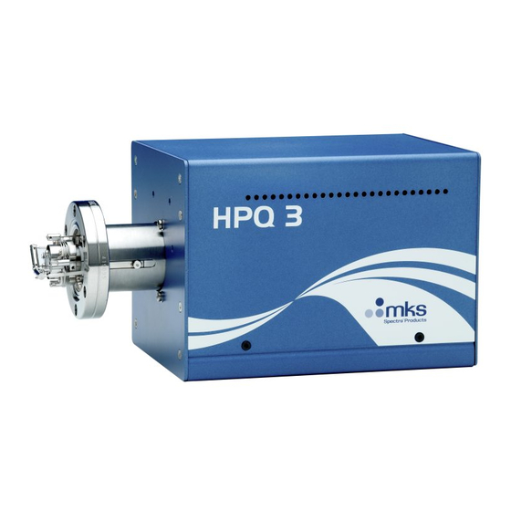
- Page 1 HPQ3 (S) Hardware Manual HPQ3 Hardware Manual – SP101019.101 October2012...
- Page 2 MKS Products provided subject to the US Export Regulations. Diversion or transfer contrary to U.S. law is prohibited. HPQ3 is a registered trademark of MKS Instruments UK Limited. Conflat® is a registered trademark of Varian Associates. Viton® is a registered trademark of E.I. DuPont de Nemours & Co., Inc.
-
Page 3: Table Of Contents
5. Connecting to the Ethernet Port 32 Temperature range 11 5.1 Adding the HPQ3 33 1.4 Safety 11 5.2 Directly connecting to the HPQ3 35 1.5 Connectors 11 5.3 Assigning a static IP Address 39 1.6 Warning labels 12 6. Baking 42 1.7 Ventilation 12... - Page 4 8. Exploded Views 56 Complete Ion-source 58 Analyser pin-outs 56 10. Returning Your Unit for Service 59 9. Spare Parts 58 Support Contact Numbers 59 Filaments 58 MKS Instruments UK Ltd HPQ3 Hardware Manual – SP101019.101 October 2012...
-
Page 5: Ec Declaration Of Conformity
I hereby declare that the equipment named above has been designed to comply with the relevant sections of the above referenced specifications. The unit complies with all essential requirements of the Directives. MKS Instruments UK Ltd HPQ3 Hardware Manual – SP101019.101 October 2012... - Page 6 Signed: J.M.Higgins General Manager October 2009 MKS Instruments UK Ltd HPQ3 Hardware Manual – SP101019.101 October 2012...
-
Page 7: Overview
Overview The HPQ3 is the latest innovation in RGA technology from MKS Instruments allowing operation far mbar of conventional RGA’s without the need for differential pumping. beyond the 1e The field proven analyser technology of the HPQ analyser coupled with the latest innovative electronics technology derived from the Microvision2 family give data quality not previously seen in this class of instrument. - Page 8 This manual focuses on HPQ3 hardware and should be used in conjunction with the relevant user interface manual during installation. Any required network communications cards should be installed and configured prior to installing the HPQ3, or RGA software if supplied.
-
Page 9: Specifications
0.6 kg Analyser Max. Operating pressure HPQ3 1e-3 Torr (1.3e-3 mbar) HPQ3S 8e-3 Torr (1e-2 mbar) – Application dependant Maximum transient burst pressure 4e-2 Torr (5e-2 mbar) – gas dependant MKS Instruments UK Ltd HPQ3 Hardware Manual – SP101019.101 October 2012... - Page 10 MKS Instruments UK Ltd HPQ3 Hardware Manual – SP101019.101 October 2012...
-
Page 11: Electrical
The protective earth conductor of the power cord must be connected to the power source protective earth terminal. There are no operator replaceable parts within the 24VDC power supply unit or the HPQ3 unit. 1.5 Connectors The connectors for external circuits are for use only with MKS equipment, or equipment which has no accessible hazardous live parts. -
Page 12: Warning Labels
On the rear panel refers to: a. Read all instructions carefully before use. b. The control unit and signal ports are designed for connection to MKS accessories via MKS supplied cables. There are no accessible hazardous voltages or currents on these ports. - Page 13 Allow a minimum clearance of 50mm all round. Do not exceed the maximum operating ambient temperature. MKS Instruments UK Ltd HPQ3 Hardware Manual – SP101019.101 October 2012...
- Page 14 5. Cables attached to all other ancillary signal and control ports must have a length of less than 3 meters. If greater length is required, MKS Instruments Ltd. must be contacted for technical guidance on possible EMC and safety issues.
- Page 15 MKS Instruments UK Ltd HPQ3 Hardware Manual – SP101019.101 October 2012...
- Page 16 THE EQUIPMENT 1. Maintenance functions must only be carried out by competent persons. 2. During the warranty period, faulty equipment must be returned to MKS Instruments, Spectra Products Ltd., unless special arrangements are made. 3. There are no user serviceable parts in the electronic equipment. Certain components are EMC and safety critical and must not be substituted.
-
Page 17: Rear Panel Connections
2. Rear Panel Connections The rear panel incorporates all the connections required by the HPQ3 RGA. Details on these connectors and their use can be found in this section. MKS Instruments UK Ltd HPQ3 Hardware Manual – SP101019.101 October 2012... -
Page 18: X-Trip
2.1 X-Trip The X-Trip connector requires a special locking, stereo jack plug, which is supplied with the unit. Do not use a standard 3.5mm jack plug. Replacements are available from MKS Instruments if required. The external trip feature is used to protect the filaments and electron multiplier from exposure to high pressures. -
Page 19: Emission Indicator
The indicator is lit when a filament is active and within correct operating parameters. 2.4 Multiplier Indicator – N/A 2.5 Power Indicator The indicator is lit when power is supplied to the HPQ3 unit. MKS Instruments UK Ltd HPQ3 Hardware Manual – SP101019.101 October 2012... -
Page 20: Gauge Connector
Differential Signal Input Low Gauge pressure output Gauge Enable Open collector to gauge Function Description 24VDC 2.7 Power A 2-pin D-type connecter used to for the 24VDC power supply. MKS Instruments UK Ltd HPQ3 Hardware Manual – SP101019.101 October 2012... -
Page 21: Analogue I/O Connector
0 – 10v Analogue Output 1 0 – 10v Analogue Output 2 NOTE: The 120mA maximum load for the power supply outputs is shared between the Digital and Analogue connectors. MKS Instruments UK Ltd HPQ3 Hardware Manual – SP101019.101 October 2012... -
Page 22: Digital I/O Connector
Note: The total power consumption on each rail (+3.3V, ±15V & +24V) for both the Analogue and Digital I/O ports must not exceed 120mA. Function Description Multiplier Trip Dedicated to Multiplier Trip (Not available on HPQ3) 0V Digital 0V Analogue -15V -15V supply output, fused at 120mA... - Page 23 +24V +24V supply output, fused at 120mA MKS Instruments UK Ltd HPQ3 Hardware Manual – SP101019.101 October 2012...
-
Page 24: Ethernet
Using this approach allows for easily interfacing between different voltage levels and logic families. 2.10 Ethernet A standard RJ45 type 10/100 Base-T Ethernet connector used to connect the HPQ3 to a host PC, hub, switch or network. Ensure you read through the network scenarios starting on Page 22 before connecting the... -
Page 25: Analyser Installation
3.1 Unpacking When you receive the HPQ3 carefully check each item before removing the foam packaging and plastic wrapping, to ensure that no physical damage has occurred during shipment. Also, make sure all items have been received correctly by checking each item against the enclosed packing slip. -
Page 26: Mks Instruments Uk Ltd
Look at each lead from the flange to its termination point to ensure that it does not touch any other element of the analyser. If any damage is noted, contact your local MKS representative for advice before fitting the quadrupole MKS Instruments UK Ltd HPQ3 Hardware Manual –... -
Page 27: Installing The Analyser
There must be at least the distances stated free of obstructions inside the vacuum chamber. If your chamber does not meet the above criteria, you should use a specially designed adapter so that the analyser may be mounted outside the chamber. Please contact your local MKS representative for assistance. -
Page 28: Mks Instruments Uk Ltd
MKS Instruments UK Ltd HPQ3 Hardware Manual – SP101019.101 October 2012... -
Page 29: Mounting The Analyser
Rotate the flange until the locating key on the feedthrough housing tube is as close to 9 o'clock as the bolt holes will allow. This will ensure that the HPQ3 is in its preferred position, although it can be mounted in any orientation. -
Page 30: Hpq3 Installation
4. HPQ3 Installation To aid installation, the HPQ3 can be mounted in any orientation, but the cooling vents on the side panels and the exhaust vent on the rear panel must not be obstructed. 4.1 Installation Rotate the locking ring on the stainless steel analyser connector so that the slot lines up with the keyway on the connector tube. -
Page 31: Mks Instruments Uk Ltd
Finally attach the line cord to the power supply. The power supply will automatically set itself to operate with the local line voltage. When power is applied, the indicator on the rear of the HPQ3 will illuminate. Care should be taken in routing and securing all cables. Avoid running any of the signal cables next to mains power cables or sources of electrical noise. -
Page 32: Connecting To The Ethernet Port
Each address is issued manually to each device by the network administrator. By default the HPQ3 is configured for Auto-IP which is by far the simplest method if you are new to networking, or are installing the HPQ3 into an existing Auto-IP or DHCP network. -
Page 33: Adding The Hpq3
The HPQ3 is to be connected to a network running BOOTP Option - Use Auto-IP If the HPQ3 is to be connected to a network running BOOTP, then your IT Specialist will need to perform certain tasks on the BOOTP Server to complete the installation. -
Page 34: Mks Instruments Uk Ltd
For details on how to assign a static IP address to the HPQ3, please see the guide on Page 26. You will need to be allocated an IP address for use by your IT Specialist, or have them perform the installation for you. -
Page 35: Directly Connecting To The Hpq3
5.2 Directly connecting to the HPQ3 If your PC or MAC is not part of a network, you may choose to connect the HPQ3 directly to the Ethernet port or a local hub. The following section describes what is required to get your unit up and running. -
Page 36: Mks Instruments Uk Ltd
If your PC or MAC is not configured for Auto-IP, you can make the following changes to enable the function. You will need to have Administrative privileges. MKS Instruments UK Ltd HPQ3 Hardware Manual – SP101019.101 October 2012... -
Page 37: Mks Instruments Uk Ltd
While the PC or MAC has been generating its automatic IP address, the HPQ3 will be attempting to generate a compatible address. You may need to wait 30 seconds after the PC or MAC has an IP address before the HPQ3 is ready. -
Page 38: Mks Instruments Uk Ltd
You can check the status of the HPQ3 by using the RGA Device Manager application on the supplied MKS Utilities CD. Double-click the RGA Device Manager icon to start the application. After a few moments the following dialog appears displaying a list of all discovered MKS RGA’s. -
Page 39: Assigning A Static Ip Address
If you are connecting to a network where static IP addresses are used, or connecting directly to your PC or MAC and wish to use fixed addressing, you will need to assign an address to the HPQ3 To help you understand this scenario, the following explanation may be of use: You have your standalone or networked PC / MAC configured to use a fixed IP address, for example 192.168.0.1. -
Page 40: Mks Instruments Uk Ltd
“Address” and “Type” fields: The “Address” field is the currently assigned IP address of the HPQ3 The “Type” field describes the scheme the HPQ3 is currently using to obtain an address. MKS Instruments UK Ltd HPQ3 Hardware Manual – SP101019.101 October 2012... -
Page 41: Mks Instruments Uk Ltd
Right-click the instrument and select “Change IP Address”. You can see that the HPQ3 is configured to receive an IP address. We must change this option to continue. MKS Instruments UK Ltd HPQ3 Hardware Manual – SP101019.101 October 2012... -
Page 42: Baking
Enter the IP address and the Subnet issued to you by your IT Specialist. The “Default Gateway” is used in situations where multiple networks exist, or for connection to the HPQ3 from outside its local network. Your IT Specialist will instruct you on what to enter here, otherwise leave it blank. -
Page 43: Analyser Maintenance
Apart from these considerations there are times when the analyser will require maintenance and these are when accidents happen i.e. the vacuum is vented with the filaments on, or someone forgets to turn on the water cooling for the oil diffusion pump. MKS Instruments UK Ltd HPQ3 Hardware Manual – SP101019.101 October 2012... -
Page 44: Ohmmeter Analyser Checks
2. Connect the other lead to the analyser flange, you should read a short circuit. If not, you have either a serious problem, or more likely a faulty meter/meter leads. If after checking your meter, an open circuit still exists, contact your nearest MKS service centre for advice. MKS Instruments UK Ltd... -
Page 45: Checking Filaments
All the pins should show an open circuit to all other pins, EXCEPT pin 4 to 8 and pin 8 to 10, which should show short-circuit as these are the filament connections. If any of the pins read short-circuit to another pin, contact your local MKS service centre with the results of your tests and they will advise you how to proceed. - Page 46 If the meter reading suggests that the filament is good but the control unit shows a filament fail, the most likely cause would be a break down in electrical continuity or contamination of the ion source. MKS Instruments UK Ltd HPQ3 Hardware Manual – SP101019.101 October 2012...
-
Page 47: Removing The Filaments
Changing filaments is the most common maintenance event with quadrupole analysers. For this reason the HPQ3 analyser has been designed to make this task as quick and easy as possible. Below is a list of the tools and equipment you will require. We recommend that you assemble the following items before you start. -
Page 48: Mks Instruments Uk Ltd
Refer to the views on the following page. MKS Instruments UK Ltd HPQ3 Hardware Manual – SP101019.101 October 2012... -
Page 49: Mks Instruments Uk Ltd
Fig. 2 Fig. 1 MKS Instruments UK Ltd HPQ3 Hardware Manual – SP101019.101 October 2012... -
Page 50: Mks Instruments Uk Ltd
If these oxides are present, it is recommended that you refer to the section on ion source cleaning on page 36 before proceeding. MKS Instruments UK Ltd HPQ3 Hardware Manual – SP101019.101 October 2012... -
Page 51: Fitting Filaments
5. Replace the analyser into your vacuum housing and again check for shorts or grounding to the outer vacuum housing. You are now ready to pump down and continue the operation of your quadrupole. Note the cut-outs for orientation of the filament plate MKS Instruments UK Ltd HPQ3 Hardware Manual – SP101019.101 October 2012... -
Page 52: Ion Source Cleaning
After the bake period, check all the screws in the ion source are tight and re-fit the analyser to the vacuum chamber. A further bake under vacuum will be required to drive off any remaining residue. MKS Instruments UK Ltd HPQ3 Hardware Manual – SP101019.101 October 2012... -
Page 53: Removing The Ion-Source To Clean Or Replace
4. Loosen the two grub-screws highlighted in red that secure the ion-source, see Fig.1. 5. Carefully withdraw the source assembly from the filter, Fig.2. Refer to the views on the following page. MKS Instruments UK Ltd HPQ3 Hardware Manual – SP101019.101 October 2012... -
Page 54: Mks Instruments Uk Ltd
Fig. 1 Fig. 2 MKS Instruments UK Ltd HPQ3 Hardware Manual – SP101019.101 October 2012... -
Page 55: Mks Instruments Uk Ltd
Refitting the ion-source is simply the reversal of the procedure for removing it. Care should be taken at all stages to ensure that no shorts are introduced and that the analyser is kept clean. MKS Instruments UK Ltd HPQ3 Hardware Manual – SP101019.101 October 2012... -
Page 56: Exploded Views
Analyser pin-outs Pin 1 is easily identified as it is the only pin with a metalized contact running through it. The pins are numbered clockwise from this pin. Pin Descriptions MKS Instruments UK Ltd HPQ3 Hardware Manual – SP101019.101 October 2012... -
Page 57: Mks Instruments Uk Ltd
Connection Earth Source plate Not Used Filament 1 Extraction plate Not Used RF.1 Filament common Not Used Filament 2 RF.2 MKS Instruments UK Ltd HPQ3 Hardware Manual – SP101019.101 October 2012... -
Page 58: Complete Ion-Source
Tungsten Yttrium Iridium 842-081 842-082 842-080 If you require a spare part not mentioned above, please contact your local MKS Instruments office for help on obtaining a part number. MKS Instruments UK Ltd HPQ3 Hardware Manual – SP101019.101 October 2012... -
Page 59: Returning Your Unit For Service
If you wish to return your instrument for service, please follow these simple guidelines. Contact your local MKS service facility to obtain a Returns Material Authorisation (RMA) number. We will require some instrument details, such as the serial numbers, date of purchase and a fault description. -
Page 60: Mks Instruments Uk Ltd
MKS Instruments UK Ltd HPQ3 Hardware Manual – SP101019.101 October 2012... -
Page 61: Mks Instruments Uk Ltd
RETURNS FORM Please complete the form and send to the appropriate MKS facility. Please ensure that we have this information before we receive the equipment. A copy should also be given to the carrier. FAILURE TO COMPLETE THIS FORM OR COMPLY WITH THE... -
Page 62: Mks Instruments Uk Ltd
Customer return address (if different from above): Name: Contact number: Equipment returned: Item 1: Serial No.: Item 2: Serial No.: Item 3: Serial No.: MKS Instruments UK Ltd HPQ3 Hardware Manual – SP101019.101 October 2012... -
Page 63: Mks Instruments Uk Ltd
Please describe the system fault in detail: Details of substances pumped, or coming into contact with the returned equipment. Chemical names: Precautions to be taken in handling these substances: MKS Instruments UK Ltd HPQ3 Hardware Manual – SP101019.101 October 2012... -
Page 64: Mks Instruments Uk Ltd
1. The equipment has been securely packaged and labelled. 2. The carrier has been informed of the hazardous nature of the consignment if applicable. Signed: Title: Date: Phone No.: MKS Instruments UK Ltd HPQ3 Hardware Manual – SP101019.101 October 2012...
Need help?
Do you have a question about the HPQ3 and is the answer not in the manual?
Questions and answers