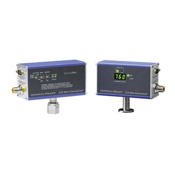
MKS Granville-Phillips Mini-Convectron 275 series Instruction Manual
Vacuum gauge module with
devicenet digital interface
Hide thumbs
Also See for Granville-Phillips Mini-Convectron 275 series:
- Instruction manual (56 pages) ,
- Quick start manual (2 pages) ,
- Instruction manual (50 pages)

Related Manuals for MKS Granville-Phillips Mini-Convectron 275 series


Summary of Contents for MKS Granville-Phillips Mini-Convectron 275 series
- Page 1 Series 275 Granville-Phillips Mini-Convectron ® ® Vacuum Gauge Module with DeviceNet Digital Interface Instruction Manual Instruction manual part number 275563 Revision F - November 2016...
- Page 3 Instruction Manual © 2016 MKS Instruments, Inc. All rights reserved. Granville-Phillips and Convectron are registered trademarks, and mksinst is a ® ® trademark of MKS Instruments, Inc. All other trademarks and registered trademarks are the properties of their respective owners.
- Page 4 ® ® Granville-Phillips Mini-Convectron Module with DeviceNet Digital Interface Catalog numbers for Series 275 Mini-Convectron Modules Mini-Convectron Module with DeviceNet, 2 Digital Setpoints, and 3-Digit Display........275538 - X X - X Mini-Convectron Module with DeviceNet, 2 Digital Setpoints, and No Digital Display .
-
Page 5: Table Of Contents
Table of Contents Chapter 1 Safety Instructions ..............7 1.1 Safety Introduction . - Page 6 Chapter 5 DeviceNet Operation ............. . . 41 5.1 DeviceNet Digital Interface Setup .
-
Page 7: Chapter 1 Safety Instructions
If you require further assistance, contact MKS, Granville-Phillips Division at the address on the title page of this manual. This product is designed and tested to offer reasonably safe service provided it is installed, operated, and serviced in strict accordance with these safety instructions. -
Page 8: Damage Requiring Service
1 Safety Instructions Do not substitute parts or modify instrument. Because of the danger of introducing additional hazards, do not install substitute parts or perform any unauthorized modification to the product. Return the product to a service facility designated by Granville−Phillips for service and repair to ensure that safety features are maintained. -
Page 9: Overpressure Conditions
1 Safety Instructions Be aware that when high voltage is present in any vacuum system, a life threatening electrical shock hazard may exist unless all exposed conductors are maintained at Earth ground. This hazard is not peculiar to this product. Be aware that an electrical discharge through a gas may couple dangerous high voltage directly to an ungrounded conductor almost as effectively as would a copper wire connection. -
Page 10: Warranty Information
Granville-Phillips Products. The MKS, Granville-Phillips Division General Terms and Conditions of Sale provides the complete and exclusive warranty for Granville-Phillips products. This document may be located on our web site at www.mksinst.com, or may be obtained by contacting an MKS, Granville-Phillips Customer Service Representative. -
Page 11: Service Guidelines
1 Safety Instructions 1.5 Service Guidelines Some minor problems are readily corrected on site. If the product requires service, contact the MKS, Granville-Phillips Division Technical Support Department at 1-303-652-4400 or 1-800-776-6543 for troubleshooting help over the phone. If the product must be returned to the factory for service, request a Return Material Authorization (RMA) from Granville-Phillips. -
Page 12: Canadian Users
1 Safety Instructions 1.7 Canadian users This Class B digital apparatus meets all requirements of the Canadian Interference-Causing Equipment Regulations. Cet appareil numerique de la classe B respecte toutes les exigences du Reglement sur le material broilleur du Canada. Series 275 Mini-Convectron Module with DeviceNet Instruction Manual - 275563... -
Page 13: Chapter 2 Introduction/Specifications
Chapter 2 Introduction/Specifications 2.1 The Mini-Convectron Gauge Module Unlike traditional thermocouple and Pirani gauges, Convectron gauges take advantage of heat loss due to convection cooling at higher pressures. This extends the range of accurate, repeatable vacuum measurements from less than 1 x 10 Torr to 1000 Torr (atmosphere) N or air. - Page 14 2 Introduction/Specifications Table 2-1 Specifications Function Description Measuring range for Air or N 1 x 1x10 to 1000 Torr –4 (See Chapter 6 of this instruction Operation in the range of 1x10 to 1x10 Torr will require periodic manual for correction curves for other verification of the zero by reducing system pressure to below 1 x –5 gases.)
-
Page 15: Module Dimensions
2 Introduction/Specifications 2.2 Module Dimensions Figure 2-2 DeviceNet Mini-Convectron Module Dimensions Table 2-3 Fitting/Flange Dimensions Fitting Description Dimension H 1/8 NPT pipe thread 1/8 NPT pipe thread / 2.2 cm (0.9 in.) 1/2 inch compression fitting 1/2 inch tubulation VCR-type female fitting 1/4 inch VCR-type female 3.0 cm (1.2 in.) fitting (standard) -
Page 16: Convectron Gauge Tube Construction
2 Introduction/Specifications 2.3 Convectron Gauge Tube Construction The transducer is a convection enhanced Pirani gauge providing rapid response, six-decades of pressure transduction, stable calibration, and good accuracy. The Pirani sensing element, R1 of the schematic of Figure 2-3, is one leg of a Wheatstone Bridge. A temperature compensating network, R2, forms the second leg of the bridge. -
Page 17: Chapter 3 Installation
Chapter 3 Installation 3.1 Receiving Inspection Inspect all material received for shipping damage. Confirm that your shipment includes all material and options ordered. If materials are missing or damaged, the carrier that made the delivery must be notified within 15 days of delivery in accordance with Interstate Commerce regulations in order to file a valid claim with the carrier. -
Page 18: Mini-Convectron Module Installation
3 Installation • Do not install the Mini-Convectron where it will be subject to corrosive gases such as mercury vapor or fluorine which will attack the gold plated sensor. • Do not use the Mini-Convectron to measure pressures of explosive gases. •... -
Page 19: Environment
3 Installation 3.3.1 Environment To minimize temperature effects, locate pressure gauges away from internal and external heat sources, in an area where the ambient temperature is reasonably constant. 3.3.2 Location Where you mount the Mini-Convectron Module is critical to obtaining reliable pressure measurements. -
Page 20: Wiring The Process Control Connector
3 Installation Figure 3-2 DeviceNet Micro Connector Table 3-1 DeviceNet Micro Connector Power Requirements Input Voltage Surge Current Operating Current Pin Connection 26 Vdc 1.5 A, 8 ms 0.2 A Pin 2 = +Vdc Pin 3 = -Vdc 11.5 Vdc 2.5 A, 8 ms 0.5 A Pin 2 = +Vdc... -
Page 21: Grounding
3 Installation 3.4.2 Grounding When high voltage is present, all exposed conductors of a vacuum system must be maintained at Earth ground. Improper grounding could cause product failure, property damage, or serious personal injury. To reduce the risk of product failure, property damage, or serious personal injury, follow ground network requirements for the facility. -
Page 22: Configure The Setpoint Relays For The Application
3 Installation 3.5 Configure the Setpoint Relays for the Application To configure setpoint relays for the module, see Section 5.2, Process Control Relays in the DeviceNet Chapter. If the module will measure the pressure of a gas other than N or air, you must adjust relay setpoints for the process gas. -
Page 23: Chapter 4 Operation
Chapter 4 Operation 4.1 Theory of Operation –4 The module measures gas pressures from 1 x 10 Torr to 1000 Torr. Vacuum chamber pressure is measured by a convection-enhanced Pirani heat-loss gauge. The Convectron gauge operates like a standard Pirani gauge, which employs the principle of a Wheatstone bridge to convert pressure to voltage, but uses convection cooling to enable accurate –4 pressure measurement, when properly calibrated, from 10... -
Page 24: Panel Indicators And Adjustments
4 Operation Using the module to measure the pressure of flammable or explosive gases can cause a fire or explosion resulting in severe property damage or personal injury. Do not use the module to measure the pressure of flammable or explosive gases. 4.2 Panel Indicators and Adjustments The two LEDs on the Display panel of the Mini-Convectron Module indicate whether the setpoint relays are actuated, and two LEDs indicate whether the digital pressure display is in Torr or milliTorr. - Page 25 4 Operation The two LEDs on the DeviceNet setup panel indicate the current status of the Mini-Convectron Module and the DeviceNet network. Three switches provide adjustments for Data Rate and Node Address settings. The two LED status indicators are explained in Section 4.2.1and Section 4.2.2; the three switches are explained in Section 4.2.3 and Section 4.2.4.
-
Page 26: Module (Mod) Led Status
4.2.1 Module (MOD) LED Status Table 4-3 Series 275 DeviceNet Mini-Convectron Module LED Status Status No Power to the module. Green Operating normally. Orange The module has an unrecoverable fault, and may need to be replaced. Flashing The module is in self test. Refer to the Identity Object in Volume II of the Orange-Green ODVA DeviceNet specification. -
Page 27: Data Rate (Baud Rate) Switches
4 Operation 4.2.3 Data Rate (Baud Rate) Switches Set the Baud Rate switch taking into account the limits due to the length of the cable between the DeviceNet controller and the Mini-Convectron Module. See Table 4-5. Table 4-5 Baud Rate Switch Settings Maximum Cable Length Baud Rate Setting 500 meters... -
Page 28: Pre-Operational Requirements
4 Operation 4.3 Pre-operational Requirements Before operating the Mini-Convectron Module, the following procedures must be performed: Install the module in accordance with the instructions given in Chapter 3, Installation. Develop a logic diagram of the process control function. Use Table 4-6 to record the proposed setpoint pressure and activation direction for each relay. See Section 5.2, Process Control Relays in the DeviceNet chapter for detailed information regarding the relay settings. -
Page 29: Gas Type
4 Operation 4.5 Gas Type The Convectron gauge in the Mini-Convectron Module is calibrated for N unless otherwise labeled for custom applications. Warning - If used improperly, Convectron Gauges can supply misleading pressure indications that can result in dangerous overpressure conditions within the system. - Page 30 4 Operation actual pressure had risen to the desired 380 Torr. Continuing to fill the system with argon to 760 Torr would result in a 24 Torr pressure reading. Depending on the pressure of the argon gas source, the chamber could be dangerously pressurized while the display continued to read about 30 Torr of N equivalent pressure.
-
Page 31: Examples
4 Operation 4.7.1 Examples Example 1 – Maximum safe indicated pressure. Assume a given vacuum system will withstand an internal pressure of 2000 Torr or 38.7 psia. For safety, you wish to limit the maximum internal pressure to 760 Torr during the backfilling process. Assume you wish to measure the pressure of Freon 22. - Page 32 4 Operation Figure 4-4 Convectron Gauge Indicated vs. True Pressure Curve; 10 to 10 Torr. Series 275 Mini-Convectron Module with DeviceNet Instruction Manual - 275563...
- Page 33 4 Operation Figure 4-5 Convectron Gauge Indicated vs. True Pressure Curve; 10 to 1000 Torr. Series 275 Mini-Convectron Module with DeviceNet Instruction Manual - 275563...
- Page 34 4 Operation Figure 4-6 Convectron Gauge Indicated vs. True Pressure Curve; 10 to 1000 Torr. Series 275 Mini-Convectron Module with DeviceNet Instruction Manual - 275563...
- Page 35 4 Operation Figure 4-7 Convectron Gauge Indicated vs. True Pressure Curve; to 10 mbar. Series 275 Mini-Convectron Module with DeviceNet Instruction Manual - 275563...
- Page 36 4 Operation Figure 4-8 Convectron Gauge Indicated vs. True Pressure Curve; to 1000 mbar. Series 275 Mini-Convectron Module with DeviceNet Instruction Manual - 275563...
- Page 37 4 Operation Figure 4-9 Convectron Gauge Indicated vs. True Pressure Curve; to 1000 mbar. Series 275 Mini-Convectron Module with DeviceNet Instruction Manual - 275563...
-
Page 38: Adjustment Of Convectron Gauge Zero And Atmospheric Pressure Indications
4 Operation 4.8 Adjustment of Convectron Gauge Zero and Atmospheric Pressure Indications Using the N calibration to pressurize a vacuum system above about 1 Torr with certain other gases can cause dangerously high pressures which may cause explosion of the system. See Section 4.7 before using with other gases. -
Page 39: Torr
4 Operation Table 4-10 Data Values for Atmosphere Calibration Pressure in Pressure in Pressure in Pressure in Altitude Altitude * Data in REAL Torr for N mbar for N Pacal for N Inches of in Feet in Meters Float Format Mercury or Air or Air... - Page 40 4 Operation NOTES Series 275 Mini-Convectron Module with DeviceNet Instruction Manual - 275563...
-
Page 41: Chapter 5 Devicenet Operation
Chapter 5 DeviceNet Operation 5.1 DeviceNet Digital Interface Setup Use the following procedure to configure the DeviceNet digital interface on the vacuum system and obtain a vacuum chamber pressure. Turn OFF power to the Mini-Convectron Gauge Module. Set the MAC ID switches on the Mini-Convectron Module to the correct address position (0 - 63) for the network on which it is installed. -
Page 42: Devicenet Protocol And Communication
5 DeviceNet Operation The DeviceNet protocol conveys two types of messages, as defined in Table. Once the Mini-Convectron Module is operating, use the polled I/O or explicit messages to perform the tasks listed in Table 5-3. Table 5-3 Network Master Connection Message Type Message Purpose Polled I/O messages... -
Page 43: Configuring Polled I/O Data Format
5 DeviceNet Operation 5.1.2 Configuring Polled I/O Data Format The 275 Mini-Convectron Vacuum Gauge Module can input data to the network in two data types and status information can be included. The default format inputs one byte of status data and floating point pressure. -
Page 44: Devicenet Error Codes
5 DeviceNet Operation 5.1.4 DeviceNet Error Codes You may use DeviceNet explicit messages or polled I/O to find out if an alarm or warning has been reported. An alarm or warning is indicated by the status byte in the input assembly, instance 2 or instance 5. An alarm is bit weight 1, and a warning is bit weight 5. -
Page 45: Check Module Status
5 DeviceNet Operation 5.1.5 Check Module Status Check the status if the Mini-Convectron Module will not read pressure due to a fault (alarm). Table 5-10 Checking the Mini-Convectron Module Status Parameter Service Class Instance Attribute Data Check Status Unassigned integer, 1 byte 5.2 Process Control Relays The module has two single-pole double-throw (normally open/normally closed) relays. - Page 46 5 DeviceNet Operation Time Deactivate Hysteresis Activate Relay Activated Activated Deactivated Figure 5-2 Default Behavior of Relays Activating with Decreasing Pressure Time Activate Hysteresis Deactivate Relay Activated Activated Deactivated Figure 5-3 Default Behavior of Relays Activating with Increasing Pressure Series 275 Mini-Convectron Module with DeviceNet Instruction Manual - 275563...
- Page 47 5 DeviceNet Operation Table 5-11 Configuring Trip Point Relays Parameter Service Class Instance Attribute Data Disable Trip 0 (default) Point Relay 1 Enable Trip Point Relay 1 Normal Polarity 0 (default) Trip Point 1 Reversed Polarity Trip Point 1 Trip Point 00 00 AF 43 Pressure (350 Torr)
-
Page 48: Get Relay Trip Points
5 DeviceNet Operation 5.2.1 Get Relay Trip Points Use the explicit messages listed in Table 5-14 to get the pressure value at which a relay activates. Table 5-12 Get Relay Trip Points Data Typical Device Service Class Instance Attribute Description Type Data 00 00 AF 43... -
Page 49: Get Relay Hysteresis
5 DeviceNet Operation 5.2.4 Get Relay Hysteresis Use the explicit messages listed in Table 5-15 to get the hysteresis for a relay. • The returned value is a percentage of activation pressure. Table 5-15 Relay Hysteresis Typical Data Service Class Instance Attribute Description... -
Page 50: Devicenet Object
5 DeviceNet Operation 5.3.3 DeviceNet Object There is a single instance of the DeviceNet Object for the Mini-Convectron Module. No class attributes are supported. Table 5-17 Explicit Message Summary - DeviceNet Object Service Class Instance Attribute Master Device Data Description Type data data... -
Page 51: Connection Object
5 DeviceNet Operation 5.3.4 Connection Object There are two instances of the Connection Object in the Mini-Convectron Module. Instance #1 is assigned to the Explicit Message Connection. Instance #2 is assigned to the Polled I/O Connection. Table 5-18 and Table 5-19 show the attributes and the predefined values of each. Table 5-18 Connection Object - Explicit Message Connection Service Class Instance Attribute Master Device... - Page 52 5 DeviceNet Operation Table 5-19 Connection Object - Polled I/O Connection Service Class Instance Attribute Master Device Data Description Type data data type None USINT Get state of the object, range Open 0–5 None USINT Get instance type, I/O Open None BYTE Get transport class trigger...
-
Page 53: Analog Sensor Object
5 DeviceNet Operation 5.3.5 Analog Sensor Object Table 5-20 Analog Sensor Object Service Class Instance Attribute Master Data Device Data Description None Get Data Type None 5D FE CE 3D Get pressure reading None Get status, alarm, or warning 5.3.6 Resets Table 5-21 Resets Service... -
Page 54: Devicenet Troubleshooting Procedures
5 DeviceNet Operation 5.4 DeviceNet Troubleshooting Procedures Table 5-22 DeviceNet Interface Troubleshooting Symptom Possible Causes Solutions The readout cannot be calibrated to 1. The gauge is incorrectly 1. Use restore factory calibration calibrated out of operating , Class command (Service 32 the specified value using range. -
Page 55: Devicenet Error Codes
5 DeviceNet Operation Table 5-25 Identity Object Status, Class 1, Instance 1, Attribute 5 Definition An object is allocated - unrelated to error condtion Configured - unrelated to error condtion Minor recoverable fault, same as bit 3, analog sensor status Minor unrecoverable fault, same as bit 1, analog sensor status I/O Status Byte and Device Supervisor Exception Status, Table 5-26... - Page 56 5 DeviceNet Operation NOTES Series 275 Mini-Convectron Module with DeviceNet Instruction Manual - 275563...
-
Page 57: Chapter 6 Service And Maintenance
Chapter 6 Service and Maintenance 6.1 Service Guidelines Some minor problems are readily corrected on site. If the product requires service, contact the MKS, Granville-Phillips Division Technical Support Department at 1-303-652-4400 or 1-800-776-6543 for troubleshooting help over the phone. If the product must be returned to the factory for service, request a Return Material Authorization (RMA) from Granville-Phillips. -
Page 58: Damage Requiring Service
6 Service and Maintenance • Do not use an ohmmeter for troubleshooting MOS circuits. Rely on voltage measurements. • Use a grounded, electrostatic discharge safe soldering iron. 6.3 Damage Requiring Service Disconnect this product from the power source and refer servicing to Qualified Service Personnel if any the following conditions exist: •... -
Page 59: Troubleshooting And Repair
6 Service and Maintenance 6.4 Troubleshooting and Repair 6.4.1 Symptoms and Possible Causes Table 6-1 General Symptoms/Possible Causes. Symptom Possible Causes The Mini-Convectron Module Check for +11 Vdc to +24 Vdc power across pins 2 and 3 of the will not power-up. DeviceNet connector. -
Page 60: Removing A Convectron Gauge From The Module
6 Service and Maintenance 6.4.2 Removing a Convectron Gauge from the Module The Convectron Gauge can be removed from the module for testing, cleaning, or replacement. The following sections provide the information required to perform those functions. Removing or replacing the Convectron gauge in a high−voltage environment can cause an electrical discharge through a gas or plasma, resulting in serious property damage or personal injury due to electrical shock. -
Page 61: Convectron Gauge Test Procedure
6 Service and Maintenance Figure 6-2 Mini-Convectron Module with Face Plate Removed Carefully unplug the Convectron gauge from the spring-loaded sockets in the printed circuit board. Figure 6-3 Convectron Gauge and PC Board Assembly 6.4.4 Convectron Gauge Test Procedure The small diameter sensor wire inside the gauge tube can be damaged by even small voltages. Do not perform electrical continuity tests with instruments applying in excess of 0.1 volt when the gauge is at vacuum, or 2 volts when at atmospheric pressure. -
Page 62: Cleaning A Contaminated Convectron Gauge
6 Service and Maintenance • Pins 1 to 2: 19 to 22 ohms • Pins 2 to 3: 50 to 60 ohms • Pins 1 to 5: 180 to 185 ohms If the resistance from pins 1 to 2 reads about 800 ohms, the sensor wire in the gauge is broken. -
Page 63: Replacing A Convectron Gauge Tube
6 Service and Maintenance Add Solvent Drain Position Fill Position Figure 6-5 Add and Drain Solvent to Clean a Convectron Gauge 6.4.6 Replacing a Convectron Gauge Tube If the gauge tube must be replaced, follow the procedures in Section 6.4.2 through Section 6.4.3 to remove the gauge tube. - Page 64 6 Service and Maintenance NOTES Series 275 Mini-Convectron Module with DeviceNet Instruction Manual - 275563...
- Page 65 Index Standard Objects Ambient operating temperature range Trip Point Relays, Setting Atmospheric Pressure Indications, Adjusting Troubleshooting Procedures DeviceNet Output Error Codes Baud Rate Error Conditions Calibration DeviceNet Cleaning a Contaminated Convectron Gauge Compatibility to UHV Connector FCC Verification DeviceNet Process Control Gas Type, Selecting Convectron Gauge Gases Other than Air or Nitrogen...
- Page 66 Gases Other than Air or Nitrogen Service Guidelines Preparing for Setpoint Relays Process Control Connector Configuring for Application Process Control Relays Specifications Setup Mini-Convectron Module & Gauge System Ground Repair Mini-Convectron Module/Gauge Theory of Operation Replacement Convectron Gauge Tubes Troubleshooting DeviceNet Symptoms and Possible Causes Safety...
- Page 68 ® ® Granville-Phillips Mini-Convectron Vacuum Gauge Module with DeviceNet Digital Interface Customer Service / Technical Support: MKS Pressure and Vacuum Measurement Solutions MKS Instruments, Inc., Granville-Phillips ® Division 6450 Dry Creek Parkway Longmont, Colorado 80503 USA Tel: 303-652-4400 Fax: 303-652-2844 Email: mks@mksinst.com...
Need help?
Do you have a question about the Granville-Phillips Mini-Convectron 275 series and is the answer not in the manual?
Questions and answers