Table of Contents
Advertisement
Quick Links
BeamWatch AM
User Notes
BeamWatch AM User Note
Document No. 50394-001
For Sales, Service or Technical Support
Phone: (435) 753-3729
Fax: (435) 753-5231
service@us.ophiropt.com
sales@us.ophiropt.co
Ophir-Spiricon, LLC
3050 North 300 West
North Logan, Utah 84341
©2020 Ophir-Spiricon, LLC
3-Feb-2020
Rev H
Service Email
Sales Email
m
Page 1
Advertisement
Table of Contents

Subscribe to Our Youtube Channel
Related Manuals for MKS Ophir BeamWatch AM


Summary of Contents for MKS Ophir BeamWatch AM
- Page 1 BeamWatch AM User Notes For Sales, Service or Technical Support Phone: (435) 753-3729 Fax: (435) 753-5231 Service Email service@us.ophiropt.com Sales Email sales@us.ophiropt.co Ophir-Spiricon, LLC 3050 North 300 West North Logan, Utah 84341 ©2020 Ophir-Spiricon, LLC BeamWatch AM User Note Document No. 50394-001 3-Feb-2020 Page 1 Rev H...
- Page 2 Dear Ophir-Spiricon Customer, Thank you for your recent purchase of the BeamWatch AM system. At Ophir-Spiricon we strive to provide the highest level of leading edge photonic measurement technology and service possible. We hope that your experience with us is a pleasant one, and anticipate the relationship we build will serve your photonic measurement needs for years to come.
-
Page 3: How To Use This Guide
How to Use this Guide Symbol Notation Indicates general information that poses no risk. Indicates important information about the product with little or no risk. Indicates warning information. Failure to follow instruction may result in harm to the user or product damage. -
Page 4: Optical Radiation Hazards
Safety While the BeamWatch AM alone does not present the user with any safety hazards, this instrument is intended for use with laser systems. Therefore, the user should be protected from any hazards that the laser system may present. The greatest hazards associated with laser systems are damage to the eyes and skin due to laser radiation. -
Page 5: General Information
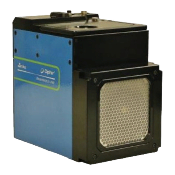
Chapter 1 General Information Introduction BeamWatch AM is the next version in Ophir-Spiricon’s family of non-interfering beam monitoring systems. Designed specifically for the additive manufacturing industry, BeamWatch AM sports a new compact design and provides real-time measurement of the beam at the working plane location. Measurement of the beam’s caustic is taken by imaging the Rayleigh scatter of the beam from the side. - Page 6 Equipment User documentation: • BeamWatch AM User Notes • Alignment tool User Notes • Calibration Certificate • Quick Start Guide BeamWatch AM Power Supply Cable Power Supply Adapter Software Installation Disc Interlock Cable Y-Distributor for Juno USB Interface Interlock Wiring Harness: •...
- Page 7 Additional 1/4" Air Hose (10ft) Retaining Ring Pliers Halo Aperture Replacement Filters (x4) Alignment Tool BeamWatch AM User Note Document No. 50394-001 3-Feb-2020 Page 7 Rev H...
- Page 8 Getting to know BeamWatch AM LED Notification Lights Three LED lights on the top of the BeamWatch AM unit provide information at a glance about operation. The Power Indicator LED shines green when the unit is receiving power. The Shutter Indicator LED shines green when the shutter is open and red when the shutter is closed. The shutter cannot open without the purge gas connected and flowing.
-
Page 9: Specifications
Specifications Beam Profiling Wavelength 1060-1080 nm Minimum Power density 1.5 Megawatts/cm Minimum Focus Spot 50 microns Maximum Beam diameter at 6 mm entrance (4.5 mm using the Halo Aperture) Communication to PC USB 2.0 & USB 3.0 Power 100-240 Volts AC 50/60Hz Clean dry gas, 3-8 SLPM (35-100 PSI / Particulate Purge 250-650 kPa). -
Page 10: Operating Space
Operating Space The graphic below gives a visual indication of the recommended operating space for BeamWatch AM. If BeamWatch is operated outside of this space, it may be difficult to see the curvature of the caustic or the beam may be large enough at the edges of the image that it is out of focus. •... -
Page 11: Mounting Hardware
Chapter 2 Setup Mounting Hardware Place the BeamWatch AM unit in the build chamber approximately where the beam can enter the input aperture unobstructed. BeamWatch AM employs three ball bearings at its base to maintain three points of contact which keeps the unit level. - Page 12 A 10 mm reference pin hole is present under the bottom plate to help aid with repeatable mounting. The bottom plate does not contain an access hole due to fan airflow. However this plate can be removed when in the build chamber. Remove the bottom plate to locate the reference pin hole.
- Page 13 After connecting the purge gas, connect the electrical components. 1. Connect the provided power cord to the power port on the BeamWatch AM unit. 2. Connect the remaining end into a surge protected 100-240 VAC outlet. 3. Connect provided USB 3.0 cable into the data source on the BeamWatch AM unit.
-
Page 14: Interlock (Optional)
Interlock (Optional) The Y-Distributor and Interlock cable are provided to allow you to integrate BeamWatch AM with your laser system. This can prevent accidentally applying the laser when the shutter is not open. 1. Connect the Y-Distributor to the power cable. 2. -
Page 15: Laser Setup
Laser Setup 1. Open the software, supply approximately 3 SLPM (35 PSI / 2.5 BAR) purge gas, and then select Open to open the shutter. Do not exceed 8 SLPM (100 PSI / 6.5 BAR). 2. Apply the guide beam. The alignment tool can only be used with a low power guide beam. - Page 16 Using the Alignment Tool 1. Insert the alignment tool into the BeamWatch AM with the cutout side facing the camera as shown. a. The alignment tool has an index to assist in guiding it into place. Hold the tool by the index and insert it into the aperture on the unit.
- Page 17 4. The beam will be displayed in the BeamWatch software as an ellipse as shown in the images below. It may be necessary to adjust the Exposure and/or Summing to bring the alignment beam to a viewable level. 5. If the beam is centered on the crosshair as shown in the properly centered example, the beam is aligned.
- Page 18 6. Remove the alignment tool and use the concept below to make any necessary fine adjustments. 7. Watch the 2D Beam Display as you align the beam. The outer two vertical lines represent the bounds of the Focal Plane Region (±350µm). Align the beam within these bounds, in both views, to get the strongest results.
-
Page 19: Operating Limits
Operating Limits The high powered lasers used in additive manufacturing generate a large amount of heat which limits how long measurements can be taken. See the chart below to see how long measurements can be taken based on Power levels. The Halo Aperture In some applications extra light besides the main beam can enter the BeamWatch AM and cause an increase in background... -
Page 20: Maintenance
Chapter 3 Maintenance Replace Air Filters Air filters should be changed every 10 hours of operation. 1. Use a flat tool, like a flathead screwdriver, to remove the Filter Retainer. 2. Remove the Filter Guards as well as the filter that is interposed between the shields. - Page 21 7. Blow a clean, dry gas onto the mirror to remove any dust buildup. If using canned air keep the can as vertical as possible to prevent any liquid getting on the mirror assembly. 8. Review the instructions in Newport cleaning kit web page.
- Page 22 Recalibration BeamWatch AM needs to be sent to Ophir-Spiricon annually (date noted on calibration label) for recalibration to maintain accurate readings. Because the calibration is stored in the wiring harness, it must be included when shipped. When shipping make sure to lock the shipping case with the provided key. Do not ship the key, the calibration team will have a key to unlock the box.
- Page 23 Appendix A Dimensions BeamWatch AM User Note Document No. 50394-001 3-Feb-2020 Page 23 Rev H...
-
Page 24: Appendix B Replacement Parts
Appendix B Replacement Parts Part Number Description Image SP90486 Retaining Ring and Wave Ring SP90487 Power Supply SP90488 Replacement Filters (4) SP90489 Filter Guards (2) SP90490 Filter Retaining Ring (2) BeamWatch AM User Note Document No. 50394-001 3-Feb-2020 Page 24 Rev H... - Page 25 Part Number Description Image Turning Mirror, 40 mm Retaining SP90491 Ring, and 40 mm Wave Spring SP90493 Halo Aperture SP90494 Alignment Tool Interlock Cable and Y-Distributor SP90495 for Interlock SP90496 Wiring Harness Newport Newport Optic Cleaning Kit Model RFCR BeamWatch AM User Note Document No.
- Page 26 Notes: BeamWatch AM User Note Document No. 50394-001 3-Feb-2020 Page 26 Rev H...
- Page 27 BeamWatch AM User Note Document No. 50394-001 3-Feb-2020 Page 27 Rev H...
- Page 28 Notice BeamWatch AM ® is a registered trademark of Ophir-Spiricon, LLC and is protected under United States Patent No. 8,988,673. Windows is a registered trademark of Microsoft Corporation. ® All rights to the product and any accompanying user guide(s) are reserved by Ophir-Spiricon, LLC. Ophir- Spiricon, LLC reserves the right to make improvements to the product described in this user guide at any time and without prior notice.
Need help?
Do you have a question about the Ophir BeamWatch AM and is the answer not in the manual?
Questions and answers