
Related Manuals for Winmate IV32


Summary of Contents for Winmate IV32
- Page 1 IV32 Motherboard 3.5” SBC with Intel ® 3 rd Generation Core™ i7 Processors HDMI, LVDS, VGA, Dual Giga Ethernet, Mini PCIe Interface User Manual / Engineering Spec. Version 1.1...
-
Page 2: Fcc Statement
Operation of this equipment in a residential area is likely to cause harmful interference in which case the user will be required to correct the interference at him own expense. IV32 Motherboard User Manual... -
Page 3: Copyright Notice
Applications that are described in this manual are for illustration purposes only. Winmate Communication Inc. makes no representation or warranty that such application will be suitable for the specified use without further testing or modification. -
Page 4: Packing List
In addition, free technical support is available from our engineers every business day. We are always ready to give advice on application requirements or specific information on the installation and operation of any of our products. Please do not hesitate to call or e-mail us. IV32 Motherboard User Manual... -
Page 5: Safety Precautions
CPU card. Modern electronic devices are very sensitive to static electric charges. As a safety precaution, use a grounding wrist strap at all times. Place all electronic components in a static-dissipative surface or static-shielded bag when they are not in the chassis. IV32 Motherboard User Manual... - Page 6 F. The equipment has obvious signs of breakage. 15. Do not leave this equipment in an uncontrolled environment where the storage temperature is below -20° C (-4°F) or above 60° C (140° F). It may damage the equipment. IV32 Motherboard User Manual...
-
Page 7: Revision History
Revision History Version Date Note Author 2015.03.26 Jumper , Connector Austin Chang 2013.06.25 Initial Draft Pirson Liang IV32 Motherboard User Manual... -
Page 8: Table Of Contents
3.2 INSTALLATION OF COM PORT‟S DRIVER ......... 27 CHAPTER 4 BIOS SETUP ...............31 4.1ENTERING BIOS SETUP ..............31 ............... 33 DVANCED ETTING 4.3CHIPSET CONFIGURATION .............. 51 4.4 BOOT SETTING .................. 57 4.5SECURITY SETUP ................59 4.6SAVE & EXIT ..................60 VIII IV32 Motherboard User Manual... -
Page 9: Chapter 1 General Information
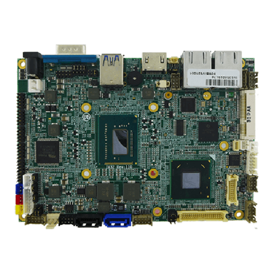
General Information This chapter includes the IV32 Motherboard background information. The section includes: • Introduction • Feature • Motherboard Specification • Function Block • Board Dimension IV32 Motherboard User Manual... - Page 10 Express Chipset HM76 to offer high definition display function, and it also supports 24-bit Dual-Channel LVDS. With all of the integrated features, IV32 SBC is designed to satisfy most of the applications in the industrial computer market, such as Gaming, POS, KIOSK, Industrial Automation, and Programmable Control System.
-
Page 11: Motherboard Specifications
3.5 inch Form Factor Dimensions 146mm x 102mm Operating Temperature: 0~60°C (32~140°F) Operating Humidity: 10~90% Relative Humidity, non-condensing Environmental Shock: Operating 15G, 11ms duration Vibration: Operating 5 Hz~500Hz / 1Grms / 3 Axis Certification: CE, FCC, RoHS IV32 Motherboard User Manual... -
Page 12: Function Block
1.4 Function Block IV32 Motherboard User Manual... -
Page 13: Board Dimension
1.5 Board Dimension IV32 Motherboard User Manual... -
Page 14: Chapter 2 Installations
Installations This chapter provides information on how to use the jumpers and connectors on the IV32 Motherboard. The section includes: Memory Module Installation ﹒ I / O Equipment Installation ﹒ Jumper and Connector Location ﹒ Jumpers ﹒ Connectors and Pin Assignment ﹒... -
Page 15: Memory Module(So-Dimm)Installation
Chapter 2 Installations 2.1 Memory Module(SO-DIMM)Installation The IV32 Motherboard provides one 204-pin SO-DIMM slot, and it supports up to 8GB DDR3 1333/1600MHz. When installing the Memory device, please follow the steps below: Step 1. Firmly insert the SO-DIMM at an angle into its slot. Align the SO-DIMM on the slot such that the notch on the SO-DIMM matches the break on the slot. -
Page 16: I / O Equipment Installation
Various adapters may come with USB ports. USB usually connect the external system to the system. The USB ports support hot plug-in connection. Whatever, you should install the device driver before you use the device. ※Note IV32 Motherboard User Manual... -
Page 17: Jumper And Connector Location
2.3 Jumper and Connector Location Component Side Solder Side IV32 Motherboard User Manual... -
Page 18: Jumpers
A pair of needle-nose pliers may be helpful when working with jumpers. If you have any doubts about the best hardware configuration for your application, contact your local distributor or sales representative before you make any changes. IV32 Motherboard User Manual... - Page 19 JP1: Clear CMOS Pin No. Functions Clear CMOS Normal (Default) JP3: COM1 Setting (RS232/422/485) Pin No. Functions RS232 (Default) RS422 RS485 JP4: COM1 Setting (RS232 or RS422/485) RS232 (Default) RS422 / 485 10-11 11-12 IV32 Motherboard User Manual...
- Page 20 JP5: Backlight Inverter VCC Selection +12V Pin No. Functions +5V (Default) +12V JP6: Backlight Inverter VCC Control BIOS Pin No. Functions BIOS (Default) JP7: Operating VDD Selection +3.3V Pin No. Functions +3.3V (Default) IV32 Motherboard User Manual...
- Page 21 JP8: Backlight Brightness Control Mode Selection Pin No. Functions DC Mode PWM Mode (Default) JP9: DC Capacitor Capacitor Pin No. Functions Capacitor N/C (Default) CON1: LCD Panel Voltage Selection Pin No. Functions +3.3V (Default) +12V IV32 Motherboard User Manual...
-
Page 22: Connectors And Pin Assignment
USB 3.0 Wafer USB 4/5 USB 2.0 Wafer USB 6/7 USB 2.0 Wafer COM2 RS232 COM3 RS232 COM4 RS232 Mini PCIe Full / Half-Size Mini PCIe Mini Card Slot For mSATA SSD Card DDR3 SO-DIMM DDR3 SO-DIMM Socket IV32 Motherboard User Manual... - Page 23 USB_PN1_C USB_PP0_C USB_PP1_C USB_GND USB_GND USB3_RXN1_C USB3_RXN2_C USB3_RXP1_C USB3_RXP2_C USB_GND USB_GND USB3_TXN1_C USB3_TXN2_C USB3_TXP1_C USB3_TXP2_C 2.5.3 HDMI 1: HDMI Connector Pin No. SYMBOL Pin No. SYMBOL HDMIB_TMDS0+ 2 HDMIB_TMDS0- HDMIB_TMDS1+ HDMIB_TMDS1- HDMIB_TMDS2+ 8 HDMIB_TMDS2- HDMIB_CLK+ HDMIB_CLK- IV32 Motherboard User Manual...
- Page 24 Pin No. SYMBOL Pin No. SYMBOL MDI0_IN+ MDI0_IN- MDI1_IN+ MDI1_IN- VLAN_12 LAN1_DGND MDI2_IN+ MDI2_IN- MDI3_IN+ MDI3_IN- LAN_VDD(1.9V) LAN_TRAFFICLED# LAN_SPD100LED# LAN_SPD1000LED# UGND UGND 2.5.5 1394b: FireWire 800 Pin No. SYMBOL Pin No. SYMBOL 1394b_TPB0+ 1394b_TPA0+ 1394b_TPB0- 1394b_TPA0- +12V IV32 Motherboard User Manual...
- Page 25 Pin No. SYMBOL Pin No. SYMBOL AZ_FOUT_R AZ_FOUT_L AUGND LINE1_R LINE1_L MIC1_R MIC1_L AUGND Font_SENSE Mic_SENSE Line_SENSE 2.5.8 VGA: VGA Internal Wafer Pin No. SYMBOL Pin No. SYMBOL DAC_SDAT0 VGA_5V DAC_SCL0 R_FILTER 3VHSYNC0 G_FILTER 3VVSYNC0 B_FILTER IV32 Motherboard User Manual...
- Page 26 SYMBOL HDMIC_TMDS2- HDMIC_TMDS2+ HDMIC_TMDS1- HDMIC_TMDS1+ HDMIC_TMDS0- HDMIC_HPD2 HDMIC_TMDS0+ HDMIC_CLK- HDMIC_CLK+ HDMIC_DDC_CLK HDMIC_DDC_DATA 2.5.10 LVDS: LVDS Port Pin No. SYMBOL Pin No. SYMBOL LCDVDD TXOUT_L0- LCDVDD TXOUT_L0+ LCDVDD TXOUT_L1- TXOUT_L1+ TXOUT_L2- TXOUT_L2+ TXCLK_L- TXCLK_L+ TXOUT_L3- TXOUT_L3+ TXOUT_U0- IV32 Motherboard User Manual...
- Page 27 TXOUT_U3- TXOUT_U3+ 2.5.11 SATA II: SATA 2.0 3Gb/s Port Pin No. SYMBOL Pin No. SYMBOL SATA_TXP SATA_TXN SATA_RXN SATA_RXP 2.5.12 SATA III: SATA 3.0 6Gb/s Port Pin No. SYMBOL Pin No. SYMBOL SATA_TXP SATA_TXN SATA_RXN SATA_RXP IV32 Motherboard User Manual...
- Page 28 ※Without power/reset OSD, short circuit pin 5 and 6 together to boot up the motherboard. Pin No. SYMBOL Pin No. SYMBOL PW_LED+ HD_LED+- PW_LED- HD_LED- PW_BT1 RT_BT1 PW_BT2 RT_BT2 RSEV 2.5.16 (3.3V /5V / 12V): Power Output Pin No. SYMBOL Pin No. SYMBOL IV32 Motherboard User Manual...
- Page 29 2.5.13 SATA Power: 3.3V/ 5V/ 12V IV32 Motherboard User Manual...
- Page 30 GPIO53_IN0 GPIO56_OUT0 GPIO54_IN1 GPIO57_OUT1 2.5.18 12V DC Input: 12V DC Power Input Wafer Pin No. SYMBOL Pin No. SYMBOL +12V 2.5.19 USB 3: USB 3.0 Wafer Pin No. SYMBOL Pin No. SYMBOL StdRx- StdRx+ StdTx- StdTx+ IV32 Motherboard User Manual...
- Page 31 2.5.21 COM2 (COM3 / COM4): RS232 Pin No. SYMBOL Pin No. SYMBOL FK_NDCD[2:4] FK_NDSR[2:4] FK_NSIN[2:4] FK_NRTS[2:4] FK_NSOUT[2:4] FK_NCTS[2:4] FK_NDTR[2:4] FK_NRI[2:4] 2.5.22 Mini PCIe: Full / Half-Size Mini PCIe Pin No. SYMBOL Pin No. SYMBOL 3.3V_MINIPCIE1 PCIE_WAKE# +V1.5S IV32 Motherboard User Manual...
- Page 32 VREG_USIM CLK_SLOT4_OE# CLK_PCIE_SLOT4_N CLK_PCIE_SLOT4_P WLAN-RFON2 BUF_PLT_RST2# +V3.3A PCIE_RXN3_SLOT4 PCIE_RXP3_SLOT4 +V1.5S SMB_CLK SMB_DATA PCIE_TXN3_SLOT4 PCIE_TXP3_SLOT4 USB_PN5 USB_PP5 3.3V_MINIPCIE1 3.3V_MINIPCIE1 3.3V_MINIPCIE1 IV32 Motherboard User Manual...
- Page 33 2.5.23 mSATA Card Slot Pin No. SYMBOL Pin No. SYMBOL +V3.3_ +V1.5S +V3.3A SATA_RXP1 SATA_RXN1 +V1.5S SATA_TXN1 SATA_TXP1 +V3.3_ +V3.3_ +V1.5S SSD_LED# +V3.3_MINIPCIE1 IV32 Motherboard User Manual...
-
Page 34: Chapter 3 Driver Installation
Driver Installation This chapter offers information on the drivers and installation utilities The section includes: • Installation of all drivers • Installation of COM Port‟s driver IV32 Motherboard User Manual... - Page 35 Chapter 3 Driver Installation 3.1 Installation of all drivers The IV32 comes with AutoRun DVD-ROM that contains all drivers, utilities, and an installation AP that will help the user to install the driver successfully. While inserting the driver DVD, an installation AP will be run automatically. After executing the AP, the UI shown below is used for driver installation.
- Page 36 2. Follow the instruction that the window shows. 3. The system will help you install the driver automatically. ® Step 5. Install Intel ME Driver 1. Click on the icon AP and Intel ME folder, and select the OS folder your system is. IV32 Motherboard User Manual...
-
Page 37: Installation Of Com Port"S Driver
Step 2. Extract the Patch_0408.zip to a folder. Step 3. Double click on the batch file (patch.bat), and the driver will be installed. Step 4. Check whether the driver has been installed successfully. Before the update or update fail. IV32 Motherboard User Manual... - Page 38 After the update and update success. Step 5. You will need to restart your computer for driver install success. Type in the following command on the Run Menu: C:\Windows\System32\UserAccountControlSettings.exe IV32 Motherboard User Manual...
- Page 39 To turn UAC back on, move the slider to choose when you want to be notified, and then click OK. If you're prompted for an administrator password or confirmation, type the password or provide confirmation. You will need to restart your computer for UAC to be turned off. IV32 Motherboard User Manual...
-
Page 40: Chapter 4 Bios Setup
BIOS Setup This chapter describes how to set up the BIOS configuration. The section includes: • Entering BIOS Setup • Advanced Setting • Chipset Configuration • Boot Setting • Security Setup • Save & Exit Setup IV32 Motherboard User Manual... - Page 41 Increase the numeric value or make changes <Page Up/+> Decrease the numeric value or make changes <Page Down/-> General help, for Setup Sub Menu <F1> Load Previous Values <F2> Load Setup Defaults <F3> Save all CMOS changes <F4> IV32 Motherboard User Manual...
- Page 42 The right frame displays the key legend. Above the key legend is an area reserved for a text message. When an option is selected in the left frame, it is highlighted in white. Often a text message will accompany it. IV32 Motherboard User Manual...
-
Page 43: Advanced Setting
4.2 Advanced Setting PCI Subsystem Setting IV32 Motherboard User Manual... - Page 44 Value to be programmed into PCI Latency Timer Register.(32~248) PCI Latency Timer Enables or Disables VGA palette registers snooping VGA Palette Snoop Enables or Disables PCI device to generate PERR# PERR# Generation Enables or Disables PCI device to generate SERR# SERR# Generation IV32 Motherboard User Manual...
- Page 45 Link Training Timeout Training” bit in link status register. Value range from 10 to 1000 uS In order to save power, software will disable unpopulated PCI express Unpopulated Links links, if this option set to „Disabled‟ IV32 Motherboard User Manual...
-
Page 46: Acpi Setting
State). This option may be not effective with some OS. Select the ACPI sleep state the system will enter, when the ACPI Sleep State SUSPEND button is pressed. Enables or Disables lock of legacy resources. Lock Legacy Resources IV32 Motherboard User Manual... - Page 47 Trusted Computing Security Device Support Enable or Disable BIOS support for security device IV32 Motherboard User Manual...
- Page 48 OS (Windows Server 2003 SP1, Windows XP SP2, SuSE Linux 9.2, RedHat Enterprise 3 Update 3.) Hardware Prefetcher Turns on/off the MLC streamer prefetcher. Adjacent Cache Line Prefetch To turn on/off prefetching of adjacent cache lines. TCC Activation offset Offset from the factory TCC activation temperature. IV32 Motherboard User Manual...
- Page 49 This item allows users to select mode of SATA controller(s). SATA Mode Selection This item allows users to enable or disable the Test mode. SATA Test Mode Enable PCH to aggressively enter link power state. Aggressive LPM Support IV32 Motherboard User Manual...
-
Page 50: Thermal Configuration
This value sets the TC1 value for the ACPI passive cooling formula. Passive TC1 value This value sets the TC2 value for the ACPI passive cooling formula. Passive TC2 value This value sets the TSP value for the ACPI passive cooling formula. Passive TSP value IV32 Motherboard User Manual... - Page 51 ® Intel Rapid Start Technology ® This item allows users to enable or disable Intel rapid start technology. PCH-FW Configuration This item allows users to enable or disable ME FW image re-flash function. IV32 Motherboard User Manual...
- Page 52 Anti-Theft Technology Configuration Intel® Anti-theft Technology ® This item allows users to enable or disable Intel AT in bios for testing only. Intel® Anti-theft Technology Rec Set the number of times recovery attempted will be allowed. IV32 Motherboard User Manual...
- Page 53 Acoustic Management Configuration Option to enable or disable automatic acoustic management. USB Configuration IV32 Motherboard User Manual...
- Page 54 Device reset time-out Maximum time the device will take before it properly report itself to the Device power-up delay host controller. SMART Setting Smart Self Test Enable or disable Run SMART Self test on all HDDs during Post. IV32 Motherboard User Manual...
- Page 55 F81866 Super I/O Configuration Serial Port Configuration Set Parameters of Serial Ports. User can Enable/Disable the serial port and Select an optimal settings for the Super IO Device. IV32 Motherboard User Manual...
- Page 56 Smart Fan Control Fan1/Fan2 Smart Fan Control This field enables or disables the smart fan feature. At a certain temperature, the fan starts turning. Once the temperature drops to a certain level, it stops turning again. IV32 Motherboard User Manual...
- Page 57 Platform Misc Configuration PCI Express Native Support Enable/Disable. This feature is only available in vista. ® Intel Smart Connect Technology Enable/Disable ISCT configuration IV32 Motherboard User Manual...
- Page 58 Windows Server OS. Terminal Type VT-UTF8 is the preferred terminal type for out-of-band management. The next best choice is VT100+ and then VT100. See above, in Console Redirection Settings page, for more Help with Terminal Type/Emulation. IV32 Motherboard User Manual...
- Page 59 ® Intel RC Drivers Version Detail CPU PPM Configuration IV32 Motherboard User Manual...
- Page 60 Short duration power limit This item allows users to enable or disable ACPI T state function. ACPI T state DTS Configuration CPU DTS This item allows users to select the ACPI thermal management uses EC reported temperature value function. IV32 Motherboard User Manual...
-
Page 61: Chipset Configuration
High Precision Timer Enables or disables the high precision timer. SLP_S4 Assertion Width This item allows users to set a delay of sorts. Restore AC Power Loss This item allows users to select off, on and last state. IV32 Motherboard User Manual... -
Page 62: Pci Express Configuration
PCIe-USB glitch W/A for bad USB device connected behind PCIe-USB Glitch W/A PCIE/PEG port. Enable or disable PCI Express subtractive decode. Subtractive Decode This item allows users to enable or disable the PCI Express PCI Express Root Port 1~7 Root Port. IV32 Motherboard User Manual... - Page 63 XHCI Mode This item allows user to enable or disable XHCI Mode. EHCI 1/2 Enables or disables the EHCI controller. USB Ports pre-port Disable Control This item allows users to enable or disable each USB port individually. IV32 Motherboard User Manual...
- Page 64 PCH Azalia Configuration This item allows user to enable or disable azalea device. BIOS Security Configuration Enable or disable SMI/BIOS/GPIO/BIOS interface/RTC RAM Lock. IV32 Motherboard User Manual...
- Page 65 System Agent Bridge Name This item allows users to enable or disable VT-d. Graphic Configuration IV32 Motherboard User Manual...
- Page 66 NB PCIe Configuration PEG0 - Gen x Select PEG0 speed. Enable PEG This item allows users to enable or disable PEG always. PEG Sampler Calibrate This item allows users to enable or disable PEG sampler calibrate function. IV32 Motherboard User Manual...
-
Page 67: Boot Setting
Memory Information 4.4 Boot Setting IV32 Motherboard User Manual... -
Page 68: Csm Parameters
INT19 Trap Response This item allows option ROMs to trap interrupt 19 Boot Option #1、#2、#3 Selects the boot sequence of the device. Set the order of the legacy devices in this group. Hard Drive BBS Priorities CSM Parameters IV32 Motherboard User Manual... -
Page 69: Security Setup
This section allows you to configure and improve your system and allows you to set up some system features according to your p reference. Administrator Password Set Setup Administrator Password. User Password Set User Password. HDD 0: FUJITSU MHY2 Set the HDD password. IV32 Motherboard User Manual... -
Page 70: Save & Exit
Discard Changes done so far to any of the setup options. Restore Defaults Restore/Load Defaults values for all the setup options. Save as User Defaults Save the changes done so far as User Defaults. Restore User Defaults Restore the User Defaults to all the setup options. IV32 Motherboard User Manual... - Page 71 Service / Update Official Website The relevant information about IV32 including the latest news and downloads will be presented in the website below: http://www.winmate.com.tw/BoxPc/EmbeddedSpec.asp?Prod=05_0156 Please go there to obtain further details of IV32 Motherboard. Company Information WinMate Communication INC. 9F, No.111-6, Shin- De Rd,. San- Chung City Taipei 241, Taiwan, R.O.C.
Need help?
Do you have a question about the IV32 and is the answer not in the manual?
Questions and answers