Table of Contents
Advertisement
Quick Links
Download this manual
See also:
User Manual
Advertisement
Table of Contents

Related Manuals for Winmate IB70


Summary of Contents for Winmate IB70
- Page 1 IB70 Motherboard ® Mini-ITX Fanless SBC with Bay Trail Intel Celeron Processor, LVDS, VGA, Dual Giga Ethernet, and Mini-PCIe Interface User Manual / Engineering Spec. Version 1.3...
- Page 2 Applications that are described in this manual are for illustration purposes only. Winmate Communication Inc. makes no representation or warranty that such application will be suitable for the specified use without further testing or...
- Page 3 IB70 Motherboard User Manual / Engineering Spec. Warranty We warrant that each of its products will be free from material and workmanship defects for a period of one year from the invoice date. If the customer discovers a defect, We will, at its option, repair or replace the defective product at no charge to the customer, provided it is returned during the warranty period of one year, with transportation charges prepaid.
- Page 4 IB70 Motherboard User Manual / Engineering Spec. Safety Precautions Warning! Always completely disconnect the power cord from your chassis whenever you work with the hardware. Do not make connections while the power is on. Sensitive electronic components can be damaged by sudden power surges. Only experienced electronic personnel should open the PC chassis.
- Page 5 IB70 Motherboard User Manual / Engineering Spec. Safety and Warranty Please read these safety instructions carefully. Please keep this user's manual for later reference. Please disconnect this equipment from any AC outlet before cleaning. Do not use liquid or spray detergents for cleaning. Use a damp cloth.
- Page 6 IB70 Motherboard User Manual / Engineering Spec. Revision History Version Date Note Author 2014.07.04 Initial Draft Jimmy Chen 2014.08.15 Block Diagram revision Jimmy Chen 2014.09.01 Add OS Selection Jimmy Chen Add USB 3.0 Driver 2015.05.08 Jimmy Chen Installation...
-
Page 7: Table Of Contents
Contents CHAPTER 1: GENERAL INFORMATION ........2 ..................2 NTRODUCTION ..................... 2 EATURES ............. 3 OTHERBOARD PECIFICATIONS ................... 4 UNCTION LOCK ................5 OARD DIMENSIONS CHAPTER 2: INSTALLATIONS ..........7 (SO-DIMM) I .......... 7 EMORY ODULE NSTALLATION I/O E ..............8 QUIPMENT NSTALLATION .............. -
Page 8: Chapter 1: General Information
IB70 Motherboard User Manual / Engineering Spec. General Information This chapter includes the IB70 Motherboard background information. Sections include: Introduction Feature Motherboard Specification Function Block Board Dimensions... -
Page 9: Features
1066/1333 MHz, up to 8GB. One SATAII interface provides ample capacity. With dual Gigabit Ethernet, four COM ports, one USB 3.0 and five USB 2.0, IB70 SBC meets the requirements of today’s various applications. Display requirements are met with rich interfaces, such as eDP, LVDS, and ®... -
Page 10: Motherboard Specifications
IB70 Motherboard User Manual / Engineering Spec. 1.3 Motherboard Specifications ® ® CPU Type Intel Celeron Bay Trail-M N2930 CPU Speed 1.83GHz ® Chipset Intel SoC Integrated BIOS AMI 64Mbit Flash Graphic Intel® Graphics Engine Dual-Channel 18/24 bit LVDS Up to 1920 x 1080 @... -
Page 11: Function Block
IB70 Motherboard User Manual / Engineering Spec. Dimensions 170mm x 170mm Operating temperature: 0 deg. C to 60 deg. C Operating Humidity: 10 ~ 90% Relative humidity, Mechanical & non-condensing environmental Shock: Operating 15G, 11ms duration Vibration: Operating 5 Hz~500Hz / 1Grms / 3 Axis Certification: CE, FCC, RoHS 1.4 Function Block... -
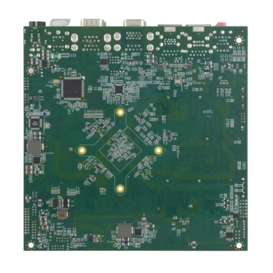
Page 12: Board Dimensions
IB70 Motherboard User Manual / Engineering Spec. 1.5 Board dimensions... -
Page 13: Chapter 2: Installations
IB70 Motherboard User Manual / Engineering Spec. Installations This chapter provides information on how to use the jumps and connectors on the IB70 Motherboard. Sections include: Memory Module Installation I / O Equipment Installation Setting the Jumpers ... -
Page 14: Memory Module (So-Dimm) Installation
Chapter 2: Installations Memory Module Installation The IB70 Motherboard provides one 204-pin SODIMM slot. The socket supports up to 4GB DDR3L 1066/1333 SDRAM. When installing the Memory device, please follow the steps below: Step.1. Firmly insert the SO-DIMM at an angle into its slot. Align the SO-DIMM on the slot such that the notch on the SO-DIMM matches the break on the slot. -
Page 15: I/O Equipment Installation
IB70 Motherboard User Manual / Engineering Spec. 2.2 I/O Equipment Installation 2.2.1 12V DC-IN *Without power/reset OSD, short circuit pin 5 and 6 together to boot up the motherboard. The Motherboard allows plugging 12V DC-IN jack on the board without ®... -
Page 16: Setting The Jumpers
IB70 Motherboard User Manual / Engineering Spec. 2.3 Setting the Jumpers... -
Page 17: Jumper Setting
IB70 Motherboard User Manual / Engineering Spec. 2.4 Jumper Setting A pair of needle-nose pliers may be helpful when working with jumpers. If you have any doubts about the best hardware configuration for your application, contact your local distributor or sales representative before you make any changes. - Page 18 IB70 Motherboard User Manual / Engineering Spec. JP1: Inverter Voltage Select Location Header Type Description Function 1-2: 5.0V Header 3*1 Inverter Voltage Select 2-3: 12 V ※ Default : 1-2 JP2 : Inverter Enable Select Location Header Type Description Function...
- Page 19 IB70 Motherboard User Manual / Engineering Spec. JP7 : Brightness Control to VRD Location Header Type Description Function 1-2: Normal Mode Brightness Control to Header 3*1 VRD(VRD PWM) 2-3: VRD Control ※ Default : 1-2 JP8, JP9 : COM Port Select...
- Page 20 IB70 Motherboard User Manual / Engineering Spec. JP10 : VRD Brightness Function Location Header Type Description Function 1-2: Analog (VR) VRD Brightness JP10 Header 3*1 Function 2-3: Digital (OSD) ※ Default : 1-2 JP11 : Clear CMOS Jump Location Header Type...
-
Page 21: Connectors And Pin Assignment
IB70 Motherboard User Manual / Engineering Spec. 2.5 Connectors and Pin Assignment The table below lists the function of each of the board’s connectors. Label Function LVDS LVDS Connector LCD Output DP LCD Output Connector HDMI HDMI Output Connector COM1... - Page 22 IB70 Motherboard User Manual / Engineering Spec. 2.5.1 LVDS: LVDS Connector Signal Name Pin Number Signal Name Number LCDVDD TXOUT_L0- LCDVDD TXOUT_L0+ LCDVDD TXOUT_L1- TXOUT_L1+ TXOUT_L2- TXOUT_L2+ TXCLK_L- TXCLK_L+ TXOUT_L3- TXOUT_L3+ TXOUT_U0- TXOUT_U0+ TXOUT_U1- TXOUT_U1+ TXOUT_U2- TXOUT_U2+ TXCLK_U- TXCLK_U+ TXOUT_U3- TXOUT_U3+ 2.5.2 DP Connector (J2)
- Page 23 IB70 Motherboard User Manual / Engineering Spec. LCDVDD DDI1_TX0_DN_EDP LCDVDD DDI1_TX0_DP_EDP LCDVDD 2.5.3 HDMI Signal Name Pin Number Signal Name Number HDMIB_TMDS0- HDMIB_TMDS2- HDMIB_TMDS0+ HDMIB_TMDS2+ HDMI_DDC_CLK HDMIB_CLK+ HDMI_DDC_DATA HDMIB_CLK- HDMI_HPD1 HDMIB_TMDS1- +V5S HDMIB_TMDS1+ +V5S 2.5.4 USB LAN2 Signal Name Pin Number...
- Page 24 IB70 Motherboard User Manual / Engineering Spec. LAN2_MDI3- LAN2_DGND 2.5.5 USB LAN3 Signal Name Pin Number Signal Name Number +5VUSB3.0 +5VUSB2.0 U2DN0 U2DN1 U2DP0 U2DP1 UGND UGND U3RXDN1 UGND U3RXDP1 UGND UGND LAN1_100_10_G U3TXDP1 LAN1_1000_O U3TXDN1 LAN1_ACTIVE_Y UGND LAN1_VDD33 UGND UGND LAN1_1.9V...
- Page 25 IB70 Motherboard User Manual / Engineering Spec. 2.5.7 Audio Connector (AUDIO1) (Line in、Front out、Mic Signal Signal Signal Name Number Name Number Number Name SW_C LINE2_JD SW_B AUGND AUGND AUGND LINE1_L AZ_FOUT_L MIC1_L LINE1_R AZ_FOUT_R MIC1_R 2.5.8 D-Sub COM (Upper)+VGA (Lower) Connector...
- Page 26 IB70 Motherboard User Manual / Engineering Spec. NDSR2 NDCD2 COM4 Pin Number Signal Name FK_NRI3 FK_NDTR3 FK_NCTS3 FK_NSOUT3 FK_NRTS3 FK_NSIN3 FK_NDSR3 FK_NDCD3 2.5.10 CPU_FAN: FAN CONNECTOR 2.5.11 PANEL1: Front Panel System Function Connector Signal Name Signal Name +V5S +V3.3S -HDD_LED...
- Page 27 IB70 Motherboard User Manual / Engineering Spec. 2.5.12 5V/12V/SATA Power: External Power SATA Power 3.3V 2.5.13 DIDO1: Digital I/O Connector Signal Name Signal Name +V5A DOUT3 DOUT1 DOUT2 DOUT0 DINT3 DINT2 DINT1 DINT0 GPIO53_IN0 GPIO56_OUT0 GPIO54_IN1 GPIO57_OUT1 2.5.14 LPT Pin Number...
- Page 28 IB70 Motherboard User Manual / Engineering Spec. 2.5.15 COM4: Serial port COM4 SYMBOL SYMBOL NRI1A NDTR1A NCTS1A NTXD1A NRTS1A NRXD1A NDCD1A NDSR1A...
-
Page 29: Chapter 3: Chipset Driver Installation
IB70 Motherboard User Manual / Engineering Spec. Chipset Driver Installation This chapter offers information on the chipset software Installation utility Standard CMOS Features... - Page 30 IB70 Motherboard User Manual / Engineering Spec. Chapter 3: Chipset Driver Installation 3.1 Standard CMOS Features Step.1. Insert the CD that comes with the motherboard. Open the file document “Chipset Driver”. Step.2. Click on “infinst_auto.exe“ to install driver.
- Page 31 IB70 Motherboard User Manual / Engineering Spec. Step.3. Click on “Yes “ to agree License Step.4. Click on “Next“ to install driver. Step.5. Click on “Next“ to install driver.
- Page 32 IB70 Motherboard User Manual / Engineering Spec. Step.7. Click on “Yes, I want to restart this computer now“ to go on.
-
Page 33: Chapter 4: Graphic Driver Installation
IB70 Motherboard User Manual / Engineering Spec. Graphic Driver Installation This Chapter offers information on the chipset software installation Utility Sections include: Installation of Graphic Driver Panel Resolution Setting... - Page 34 Graphic Driver Installation Installation of Graphic Driver IB70 Motherboard is equipped with Intel SoC Integrated chipset Device. The Intel Graphic Drivers should be installed first, and it will enable “Video Controller (VGA compatible). Follow the instructions below to complete the installation.
- Page 35 IB70 Motherboard User Manual / Engineering Spec. Step.3. Click on “Next “ to install Driver. Step.4. Click on “Yes “ to agree License.
- Page 36 IB70 Motherboard User Manual / Engineering Spec. Step.5. Click on “Next “ to install Driver. Step.6. Click on “Next “ to install Driver.
- Page 37 IB70 Motherboard User Manual / Engineering Spec. Step.7. Click on “Yes, I want to restart this computer now“ to go on.
-
Page 38: Panel Resolution Setting
IB70 Motherboard User Manual / Engineering Spec. 4.2 Panel Resolution Setting Step.1. Right-click the desktop, and then click Properties. Step.2. In the Display Properties dialog box, click the Settings tab. Step.3. Click on “Monitor”. - Page 39 IB70 Motherboard User Manual / Engineering Spec. Step.4. Click on “Hide modes that this monitor cannot display” to remove this option. Step.5. Click on “Setting”, then could choose 32bit color qualify.
-
Page 40: Chapter 5: Ethernet Driver Installation
IB70 Motherboard User Manual / Engineering Spec. Ethernet Driver Installation This chapter offers information on the Ethernet software installation utility. Sections include: Installation of Ethernet Driver... - Page 41 Ethernet Driver Installation 5.1 Installation of Ethernet Driver The Users must make sure which operating system you are using in the IB70 Motherboard before installing the Ethernet drivers. Follow the steps below to complete the installation of the Intel WG82574L Gigabit Ethernet controller LAN drivers.
- Page 42 IB70 Motherboard User Manual / Engineering Spec. Step.4. Click on “Browse my computer for driver software“ to install driver. Step.5. Choose the path to install driver.
- Page 43 IB70 Motherboard User Manual / Engineering Spec. Step.6. Click on “Close“ and go on.
-
Page 44: Chapter 6: Audio Driver Installation
IB70 Motherboard User Manual / Engineering Spec. Audio Driver Installation This chapter offers information on the Audio software installation utility. Sections include: Introduction Installation of Audio Driver ... - Page 45 6.2 Installation of Audio Driver The users must make sure which operating system you are using in the IB70 Motherboard before installing the Audio drivers. Follow the steps below to complete the installation of the Realtek ALC886 Audio drivers. You will quickly complete the installation.
- Page 46 IB70 Motherboard User Manual / Engineering Spec. Step.2. Click on “Yes“ to install driver. Step.3. Click on “Yes, I want to restart my computer now” to finish installation.
-
Page 47: Chapter 7: Usb 3.0 Installation
IB70 Motherboard User Manual / Engineering Spec. USB 3.0 Installation This chapter offers information on the USB 3.0 driver installation utility. Installation... - Page 48 IB70 Motherboard User Manual / Engineering Spec. Chapter 7: USB 3.0 Installation 7.1 Installation IH32 Motherboard is designed with Intel mobile Core i5 dual core CPU with the Intel® USB 3.0 eXtensible Host Controller. You need to install the Intel® USB 3.0 eXtensible Host Controller driver to enable the function.
- Page 49 IB70 Motherboard User Manual / Engineering Spec. Step.4. Read License Agreement and click “Yes” to proceed. Step.5. Review Readme File Information click “Next” proceed.
- Page 50 IB70 Motherboard User Manual / Engineering Spec. Step.6.When the “Setup Progress” is complete click “Next” to proceed. Step.7.When the “Setup Progress” is complete click “Next” to proceed.
- Page 51 IB70 Motherboard User Manual / Engineering Spec. Step.8. Lastly, the “Setup Complete” screen appears so click “Finish” to restart your computer.
-
Page 52: Installation
IB70 Motherboard User Manual / Engineering Spec. Fintek COM Port Driver Installation This chapter describes the step by step method to install the Fintek COM port driver. Installation... - Page 53 IB70 Motherboard User Manual / Engineering Spec. Chapter 8: Fintek Port Driver Installation STEP 1.If the system is WIN7 please first do close UAC.(Refer following “Disabling User Account Control (UAC) in Windows 7”) STEP 2.Extract the Patch_0408.zip to a folder.
- Page 54 IB70 Motherboard User Manual / Engineering Spec. STEP 5.You will need to restart your computer for driver install success. Type in this command from the Run menu: C:\Windows\System32\UserAccountControlSettings.exe To turn off UAC, move the slider to the Never notify position, and then click OK.
- Page 55 IB70 Motherboard User Manual / Engineering Spec. To turn UAC back on, move the slider to choose when you want to be notified, and then click OK. If you're prompted for an administrator password or confirmation, type the password or provide confirmation.
-
Page 56: Ami Bios Setup
IB70 Motherboard User Manual / Engineering Spec. AMI BIOS Setup This chapter describes how to set up the BIOS configuration How and When to Use BIOS Setup BIOS Functions Using Recovery Wizard to Restore Computer... -
Page 57: Chapter 9: Ami Bios Setup
IB70 Motherboard User Manual / Engineering Spec. Chapter 9: AMI BIOS SETUP 9.1 How and When to Use BIOS Setup For enter to the Tablet PC BIOS setup, you need to connect with an external USB keyboard, press “Del” key when the prompt appears on the screen during start up. -
Page 58: Bios Functions
IB70 Motherboard User Manual / Engineering Spec. 9.2 BIOS Functions 9.2.1 Main Menu The Main menu contains the information of the Tablet system including BIOS version, processor RC version, system language, time, and date. 9.2.2 Advanced Menu The Advanced menu contains the selections of PXE OpROM and Watch Dog Timer, and the settings of PCI Subsystem, ACPI, and S5 RTC Wake. - Page 59 IB70 Motherboard User Manual / Engineering Spec. 1. CPU Configuration 2. Thermal Configuration...
- Page 60 IB70 Motherboard User Manual / Engineering Spec. 3. IDE / SATA Configuration 4. USB Configuration...
- Page 61 IB70 Motherboard User Manual / Engineering Spec. 5. PPM Configuration 6. OS Selection...
- Page 62 IB70 Motherboard User Manual / Engineering Spec. 9.2.3 Chipset Menu The Chipset menu contains the information of North Bridge and South Bridge. 9.2.4 Boot Menu The Boot menu sets the sequence of the devices to be searched for the operating system.
- Page 63 IB70 Motherboard User Manual / Engineering Spec. 9.2.5 Security Menu In the Security menu, users can set Administrator Password, User Password, and HDD Security Configuration. 9.2.6 Save & Exit Menu The Exit menu displays ways of exiting BIOS Setup utility. After finishing with your settings, you must save and exit so that the changes can take effect.
- Page 64 IB70 Motherboard User Manual / Engineering Spec. Discarding Changes and Exit exits BIOS Setup utility without saving the changes you have made. Save Canges and Rest saves the changes you have made and resets BIOS system. Discarding Changes and Reset resets BIOS system without saving the changes you have made.
-
Page 65: Using Recovery Wizard To Restore Computer
PC to enable quick one-key recovery process. This partition occupies about 11GB of the storage space, and comes built-in to each IB70 series PC. Warning: Before starting the recovery process, be sure to backup all user data, as all data will be lost after the recovery process. - Page 66 IB70 Motherboard User Manual / Engineering Spec. Wait till the recovery process to complete. During the recovery process, a command prompt will show up to indicate the percent of recovery process. After recovery is completed, and the tablet computer will restart automatically.
- Page 67 IB70 Motherboard User Manual / Engineering Spec. Service / Update Official Website The relevant information about IB70 including the latest news and downloads will be presented in the website below: http://www.winmate.com.tw/BoxPc/EmbeddedSpec.asp?Prod=05_0156 Please go there to obtain further details of IB70 Motherboard.
-
Page 68: Chapter 10: Appendix
IB70 Motherboard User Manual / Engineering Spec. Appendix This chapter includes appendix items for this user manual... -
Page 69: Note1: Digital I/O Sample Code
Engineering Spec. Chapter 10: Appendix 10.1 Note1: Digital I/O Sample Code To find the Digital I/O Sample code, please refer to the IB70 driver CD SDK or contact us. 10.2 Note2: Watchdog Sample Code To find the Watchdog Sample code, please refer to the IB70 driver CD SDK or...
Need help?
Do you have a question about the IB70 and is the answer not in the manual?
Questions and answers