Winmate IK70 User Manual
Mini-itx sbc with intel 6th generation core i3/i5/i7 processor, hdmi,
display port, lvds, dual giga ethernet, usb 3.0 and ngff interface
Hide thumbs
Also See for IK70:
- User manual (108 pages) ,
- User manual (100 pages) ,
- User manual (108 pages)

Subscribe to Our Youtube Channel
Related Manuals for Winmate IK70


Summary of Contents for Winmate IK70
-
Page 1: User Manual
IK70 Motherboard Mini-ITX SBC with Intel® 6th Generation Core i3/i5/i7 processor, HDMI, Display Port, LVDS, Dual Giga Ethernet, USB 3.0 and NGFF Interface V100 User Manual Version 1.0 9171111I103R... -
Page 2: Table Of Contents
USER MANUAL CONTENTS CONTENTS PREFACE ..............................- 4 - ABOUT THIS USER MANUAL ........................- 8 - CHAPTER 1: GENERAL INFORMATION ....................- 10 - 1.1 I ............................ - 10 - NTRODUCTION 1.2 F ............................- 10 - EATURES 1.3 M ...................... - Page 3 USER MANUAL CONTENTS 3.1 C ..........................- 41 - HIPSET RIVER 3.2 G ..........................- 45 - RAPHIC RIVER 3.3 M (ME) .NET F ..............- 49 - ANAGEMENT NGINE RAMEWORK RIVER 3.4 A ............................ - 53 - UDIO RIVER 3.5 E ..........................
-
Page 4: Preface
USER MANUAL PREFACE PREFACE Copyright Notice No part of this document may be reproduced, copied, translated, or transmitted in any form or by any means, electronic or mechanical, for any purpose, without the prior written permission of the original manufacturer. Trademark Acknowledgement Brand and product names are trademarks or registered trademarks of their respective owners. -
Page 5: Packing List
USER MANUAL PREFACE Packing List Before using this Motherboard, please make sure that all the items listed below are present in your package: IK0 Motherboard User Manual & Driver CD If any of these items are missing or damaged, contact your distributor or sales representative immediately. - Page 6 USER MANUAL PREFACE Advisory Conventions Four types of advisories are used throughout the user manual to provide helpful information or to alert you to the potential for hardware damage or personal injury. These are Notes, Important, Cautions, and Warnings. The following is an example of each type of advisory.
-
Page 7: Safety Precautions
USER MANUAL PREFACE Safety Precautions CAUTION Always ground yourself to remove any static charge before touching the CPU card. Modern electronic devices are very sensitive to static electric charges. As a safety precaution, use a grounding wrist strap at all times. Place all electronic components in a static-dissipative surface or static-shielded bag when they are not in the chassis. -
Page 8: About This User Manual
This User Manual provides information about using the IK70 Motherboard. The documentation set for the IK70 Motherboard provides information for specific user needs, and includes: IK70 Motherboard User Manual – contains detailed description on how to use the motherboard, its components and features. NOTE: Some pictures in this guide are samples and can differ from actual product. -
Page 9: Chapter 1: General Information
USER MANUAL CHAPTER 1 GENERAL INFORMATION GENERAL INFORMATION This chapter includes the IK70 Motherboard background information. Introduction Features Motherboard Specifications Functional Description Physical Description - 9 -... -
Page 10: Introduction
This chapter includes the IK70 Motherboard background information. 1.1 Introduction Thank you for choosing the IK70 Motherboard. The IK70 Motherboard is powered by Intel® Q170 chipset, 17x17 mm, and Socket G3 Intel® 6th Generation Core i7/i5/i3 Processor. The Intel®6th Generation Core™ processor based on 64-bit, multi-core processors built on 22-nanometer process technology. -
Page 11: Motherboard Specifications
USER MANUAL CHAPTER 1 GENERAL INFORMATION 1.3 Motherboard Specifications Model Name IK70 Intel® Skylake-S LGA1151 2 Cores/4 Threads TDP35W Chipset Intel® 8 Series Chipset (Q170) System 2 x SO-DIMM socket ® socket DDR4-1866/2133 ECC Memory Max. 32GB ( 2 x 16GB DIMMs) - Page 12 Temp. Environment Storage -40°C ~ 70°C Considerations Temp. Operating 10% ~ 95%, non-condensing Humidity Power Input +12V Power Input Power Power Management Maximum 50W Consumption IK70-100 Single Board Computer Packing List Standard IK70 Manual & Driver CD - 12 -...
-
Page 13: Functional Description
USER MANUAL CHAPTER 1 GENERAL INFORMATION 1.4 Functional Description Function block (V100) - 13 -... -
Page 14: Physical Description
USER MANUAL CHAPTER 1 GENERAL INFORMATION 1.5 Physical Description Board Dimensions (V100) - 14 -... -
Page 15: Chapter 2: Hardware Installation
USER MANUAL CHAPTER 2 HARDWARE INSTALLATION HARDWARE INSTALLATION This chapter provides information on how to use jumpers and connectors on the IK70 motherboard. Motherboard Components Memory Module Installation I/O Equipment Installation Jumper Settings Motherboard Connectors - 15 -... -
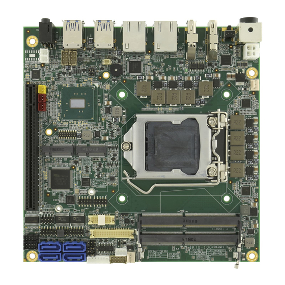
Page 16: Motherboard Components
HARDWARE INSTALLATION CHAPTER 2: HARDWARE INSTALLATION This chapter provides information on how to use jumpers and connectors on the IK70 Motherboard. Be cautious while working with these modules. Carefully read the content of this chapter in order to avoid any damages. -
Page 17: I/O Side
USER MANUAL CHAPTER 2 HARDWARE INSTALLATION 2.1.2 I/O Side 2.1.3 Solder Side - 17 -... -
Page 18: Memory Module (So-Dimm) Installation
HARDWARE INSTALLATION 2.2 Memory Module (SO-DIMM) Installation The IK70 SBC Motherboard has two 260-pin SODIMM slot. The socket supports DDR4. When installing the memory unit, please follow the steps below: 1. Firmly insert the SO-DIMM at an angle of about 30-degree into the slot. Align the SO-DIMM with the slot until it is fully inserted. -
Page 19: I/O Equipment Installation
HARDWARE INSTALLATION 2.3 I/O Equipment Installation 2.3.1 12V DC in The IK70 Motherboard allows plugging 12V DC-IN jack on the board without another power module converter under power consumption by Intel® 6th Generation Core i7/i5/i3 Processor and Q170 chipset. 2.3.2 Serial COM Port Four COM Port Pin Headers build in the motherboard. -
Page 20: Jumper Settings
USER MANUAL CHAPTER 2 HARDWARE INSTALLATION 2.4 Jumper Settings This section explains how to set jumpers for correct configuration of the motherboard. NOTE: A pair of needle nose pliers may be helpful when working with jumpers. If you have any doubts about the best hardware configuration for your application, contact your local distributor or sales representative before you make any changes. -
Page 21: Jp1: Panel Power Select
USER MANUAL CHAPTER 2 HARDWARE INSTALLATION 2.4.1 JP1: Panel Power Select Pin № Name 1-2 (Default) +3.3V +12V 2.4.2 JP2: Backlight Power Select Pin № Name 1-2 (Default) +12V 2.4.3 JP3: Backlight Dimming Select Pin № Name 1-2 (Default) PWM Mode DC Mode 2.4.4 JP4: Backlight Dimming Control Select Pin №... -
Page 22: Clr_Cmos: Clear Cmos Jumper
USER MANUAL CHAPTER 2 HARDWARE INSTALLATION 2.4.6 CLR_CMOS: Clear CMOS Jumper Remember to set jumper back to Normal before turning on the power supply. CAUTION TURN OFF the power supply before setting Clear CMOS. Pin № Function Clear CMOS 2-3 (Default) Normal 2.4.7 CLR_RTC: Clear RTC Jumper Pin №... -
Page 23: Mainboard Connectors
USER MANUAL CHAPTER 2 HARDWARE INSTALLATION 2.5 Mainboard Connectors 2.5.1 Internal Front Side Connectors Connectors Label Function Note Power 4P Wafer Wafer 4p dip QJ3119C-WFB1-4F vertical HDMI Port Connector H:15mm Display Port Connector 3VD21203-H7U0-4H SHB Express PCIEx16 16x164p180°2EG08217-D2D NGFF M.2 KEY B Connector NGFF M.2 KEY B Connector NGFF M.2 KEY E Connector NXSE0-S6705-TP50... - Page 24 USER MANUAL CHAPTER 2 HARDWARE INSTALLATION SATA3,SATA4 SATA_PWR1, SATA Power Connector 2*5p P:2.0mm DIP 180° SATA_PWR2 FAN1, FAN2 Fan Connector 3P 2.54mm DIP 180° ASAA82X-EASB0-7H 9.2mm 1.2V DDR4 SO-DIMM AS0AB26-H2SB-7H 5.2mm AS0AB26-H2SB-7H 5.2mm 1.2V 1.2V SMT USB2.0 Wafer 2*4p P:2.0mm DIP 180o 2.5.1.1 CN2: Power 4P Wafer Pin №...
- Page 25 USER MANUAL CHAPTER 2 HARDWARE INSTALLATION 2.5.1.2 CN6: SHB Express PCIEx16 Side B Description Side A Description SMB_SHB_CLK PCIE 12V power SMB_SHB_DATA External pull down Side B Side A PCIE 12V power PCIE 12V power Side B Side A SHB_TDI PCIE 12V power SHB_TCK PCIE 12V power...
- Page 26 USER MANUAL CHAPTER 2 HARDWARE INSTALLATION HSOP_6 SHB_PCIE_A6_TXP PCIE Group A TX6+ Side A CLK_PCIE_SHB_A2_P PCIE Group A TX6- Side B Side A CLK_PCIE_SHB_A2_N PCIE Group A RX6+ Side B Side A CLK_PCIE_SHB_A3_P PCIE Group A RX6- Side B Side A PCIE Group A TX7+ CLK_PCIE_SHB_A3_N Side B...
- Page 27 USER MANUAL CHAPTER 2 HARDWARE INSTALLATION 2.5.1.3 CN8: NGFF M.2 KEY E Connector IK70 Mini-PCIe connector supports 2 Mini-PCIe card application: PCIe I/F (Default) USB WWAN modem with SIM card Interface (Default) 2.5.1.4 CN9: Digital Input / Digital Output Pin №...
- Page 28 USER MANUAL CHAPTER 2 HARDWARE INSTALLATION 2.5.1.6 CN11: eDP Connector Pin № Signal Name Pin № Signal Name DP_TXP0_C LCDVDD DP_TXN0_C LCDVDD +VCC_EDP_BKLT DP_TXP1_C +VCC_EDP_BKLT DP_TXN1_C +VCC_EDP_BKLT EDP_HPD EMB_AUXP EMB_AUXN L_BKLT_EN L_BKLT_CTRL - 28 -...
- Page 29 USER MANUAL CHAPTER 2 HARDWARE INSTALLATION 2.5.1.7 CN12: LVDS Connector CN12 Pin № Signal Name Pin № Signal Name LCDVDD LVDS0_TX0_N LCDVDD LVDS0_TX0_P LCDVDD LVDS0_TX1_N LVDS0_TX1_P LVDS0_TX2_N LVDS0_TX2_P LVDS0_CLK_N LVDS0_CLK_P LVDS0_TX3_N LVDS0_TX3_P LVDS1_TX0_N LVDS1_TX0_P LVDS1_TX1_N LVDS1_TX1_P LVDS1_TX2_N LVDS1_TX2_P LVDS1_CLK_N LVDS1_CLK_P LVDS1_TX3_N LVDS1_TX3_P - 29 -...
- Page 30 USER MANUAL CHAPTER 2 HARDWARE INSTALLATION 2.5.1.8 CN13: Backlight Connector Pin № Signal Name +BKLPWR_R +BKLPWR_R +BKLPWR_R BRIGHT BLON_5V 2.5.1.9 CN14: Backlight Brightness Control VR Knob Pin № Signal Name +V5S VRD_ADC 2.5.1.10 CN15, CN16, CN17: Power Output Wafer - 30 -...
- Page 31 USER MANUAL CHAPTER 2 HARDWARE INSTALLATION 2.5.1.11 CN18: RTC Wafer Pin № Signal Name BACKUP_VBAT 2.5.1.12 CN19: BIOS Download Header Pin № Signal Name Pin № Signal Name SPI0_CS0_N SPI_TPM_GPIO SPI0_CS1_N +V3.3M SPI0_CLK SPI0_IO2 SPI0_IO3 SPI0_MISO +V3.3M SPI0_MOSI SPI0_CS2_N +V3.3M SER_IRQ SPI_TPM_PIRQ +V3.3M...
- Page 32 USER MANUAL CHAPTER 2 HARDWARE INSTALLATION 2.5.1.13 CN20, CN21: USB2.0 Wafer Signal Signal Signal Name Signal № Name № Name № № Name USB_VCC USB_VCC9 USB_VCC8 USB_VCC USB_DN USB_DN USB_DN USB_DN USB_DP USB_DP USB_DP USB_DP 2.5.1.14 CN22: ISP PORT Pin № Signal Name Pin №...
- Page 33 USER MANUAL CHAPTER 2 HARDWARE INSTALLATION 2.5.1.17 COM3, COM4, COM5, COM6: Internal RS232 COM The serial port which is Winbond I/O support is RS232 only. Signal Signal Name Pin № Signal Signal № Name № Name № Name DCDE# DSRE# DCDF# DSRF# RXDE...
- Page 34 USER MANUAL CHAPTER 2 HARDWARE INSTALLATION 2.5.1.18 PANEL 1: Front Panel Pin Header Pin № Signal Name Pin № Signal Name PW_LED+ HD_LED+ HD_LED- PW_BT BRI+ RST-BT BRI- 5VSB 2.5.1.19 SATA1, SATA2, SATA3, SATA4: SATA Connector Pin № Signal Name Pin №...
- Page 35 USER MANUAL CHAPTER 2 HARDWARE INSTALLATION 2.5.1.21 FAN1, FAN2: Fan Connector FAN1 FAN2 2.5.1.22 J2: DDR4 SO-DIMM 2.5.1.23 J3: DDR4 SO-DIMM - 35 -...
- Page 36 USER MANUAL CHAPTER 2 HARDWARE INSTALLATION 2.5.1.24 J5: BIOS Download Header Pin № Signal Name Pin № Signal Name SPI0_CS0_N SPI_TPM_GPIO SPI0_CS1_N +V3.3M SPI0_CLK SPI0_IO2 SPI0_IO3 SPI0_MISO +V3.3M SPI0_MOSI SPI0_CS2_N +V3.3M SER_IRQ SPI_TPM_PIRQ +V3.3M BUF_PLT_RST_N +V3.3M *Pin 3 must be change from PM_RSMRST#_R after EVT test. Intel ISP Adaptor Cable Description: The Intel ISP Adaptor A is only used to connect SF100 to Intel Motherboard.
-
Page 37: External I/O Side Connectors
Clear COM, Reset Button USB1, USB2 USB 3.0 USB Type A 2.5.2.1 CN1 (Power 4P Terminal Block Connector The DC power input for the IK70 Motherboard allows a voltage input of 12V DC. Pin № Signal Name Pin № Signal Name 12VDC 12VDC 2.5.2.2 CN3/ HDMI1 (HDMI 1.4a) - Page 38 Lane 3+ Lane 3- AUX_EN_N AUX+ AUX- Hot Plug +3.3V 2.5.2.4 CN4 (Audio Jack) IK70 has two stereo audio ports with phone jack connectors, one is Line-out, and the other one is Mic-in. Color Signal Name Line-out Mic-in CN24 CN23...
- Page 39 HARDWARE INSTALLATION 2.5.2.5 LAN1, LAN2 (Gigabit Ethernet) IK70 has two Ethernet connectors located on the front. Ethernet ports provide a standard RJ45 10/100/1000 Mbps jack connector with LED indicators on the front side to show its Active/ Link status and Speed status.
-
Page 40: Chapter 3: Driver Installation
USER MANUAL CHAPTER 3 DRIVER INSTALLATION DRIVER INSTALLATION This chapter contains driver installation instructions for IK70 motherboard. 3.1 Chipset Driver Installation 3.2 Graphic Driver Installation 3.3 Management Engine (ME) and .NET Framework 3.4 Audio Driver Installation 3.5 Ethernet Driver Installation 3.6 RST Driver Installation... -
Page 41: Chipset Driver
This chapter contains driver installation guide. Follow the instructions below to complete the installation. You will quickly complete the installation. This chapter provides instructions on how to install drivers on the IK70 Motherboard. 3.1 Chipset Driver Follow instructions below to install Chipset driver. - Page 42 USER MANUAL CHAPTER 3 DRIVER INSTALLATION 2. Installation window will pop up, select Next. 3. Select Accept to agree with the terms of license agreement. - 42 -...
- Page 43 USER MANUAL CHAPTER 3 DRIVER INSTALLATION 4. Check the ReadMe file information, select Install to continue. 5. Wait for the driver to be installed. - 43 -...
- Page 44 USER MANUAL CHAPTER 3 DRIVER INSTALLATION 6. When installation completed, select Restart Now to restart your computer. - 44 -...
-
Page 45: Graphic Driver
USER MANUAL CHAPTER 3 DRIVER INSTALLATION 3.2 Graphic Driver Follow instructions below to install Graphic driver. 1. Open the Driver CD (included in the package) and select Graphic driver. 2. Installation window will pop up, select Next. - 45 -... - Page 46 USER MANUAL CHAPTER 3 DRIVER INSTALLATION 3. Select Accept to agree with the terms of license agreement. 4. Check the ReadMe file information, select Install to continue. - 46 -...
- Page 47 USER MANUAL CHAPTER 3 DRIVER INSTALLATION 5. Wait for the driver to be installed. 6. Select Next to continue. - 47 -...
- Page 48 USER MANUAL CHAPTER 3 DRIVER INSTALLATION 7. After installation is completed, select “Yes, I want to restart this computer now”, and click Finish. - 48 -...
-
Page 49: Management Engine (Me) And .Net Framework Driver
USER MANUAL CHAPTER 3 DRIVER INSTALLATION 3.3 Management Engine (ME) and .NET Framework Driver Follow instructions below to install Management Engine (ME) and .NET Framework 1.1 driver. 1. Open the Driver CD (included in the package) and select ME driver. 2. - Page 50 USER MANUAL CHAPTER 3 DRIVER INSTALLATION 3. Select .NET Framework 1.1. 4. Select Yes to start the installation. 5. Wait for the driver to be installed. - 50 -...
- Page 51 USER MANUAL CHAPTER 3 DRIVER INSTALLATION 6. When installation completed, select Restart Now to restart your computer. 7. Again select the ME to continue installation. Select Next. 8. Please check the license agreement, and then select Next. - 51 -...
- Page 52 USER MANUAL CHAPTER 3 DRIVER INSTALLATION 9. Select Next to start the installation. 10. Wait for the driver to be installed. 11. When installation completed, select Finish complete installation. - 52 -...
-
Page 53: Audio Driver
USER MANUAL CHAPTER 3 DRIVER INSTALLATION 3.4 Audio Driver Follow instructions below to install Audio driver. 1. Open the Driver CD (included in the package) and select Audio driver. 2. Select Next to continue. - 53 -... - Page 54 USER MANUAL CHAPTER 3 DRIVER INSTALLATION 3. Wait for the driver to be installed. 4. When installation completed, select Finish complete installation. - 54 -...
-
Page 55: Ethernet Driver
USER MANUAL CHAPTER 3 DRIVER INSTALLATION 3.5 Ethernet Driver Follow instructions below to install LAN driver. 1. Open the Driver CD (included in the package) and select LAN driver. 2. Compression has started. - 55 -... - Page 56 USER MANUAL CHAPTER 3 DRIVER INSTALLATION 3. When compression is complete, select Next. 4. Read the license agreement, and then select Next. 5. System displays the installed packages, select Next. - 56 -...
- Page 57 USER MANUAL CHAPTER 3 DRIVER INSTALLATION 6. Confirm the installation, select Install to start the installation. 7. Wait for installation to complete. 8. When installation is completed, select Finish to close the window. - 57 -...
-
Page 58: Rst Driver
USER MANUAL CHAPTER 3 DRIVER INSTALLATION 3.6 RST Driver Follow instructions below to install RTS driver. 1. Open the Driver CD (included in the package) and select RTS driver. 2. Select Next to continue. - 58 -... - Page 59 USER MANUAL CHAPTER 3 DRIVER INSTALLATION 3. Read the license agreement, and then select Next. 4. Select Next to continue. 5. Select Next to start the installation. - 59 -...
- Page 60 USER MANUAL CHAPTER 3 DRIVER INSTALLATION 6. Wait for installation to complete. 7. Warning message will pop up, select Install. 8. Installation continues. - 60 -...
- Page 61 USER MANUAL CHAPTER 3 DRIVER INSTALLATION 9. When installation is completed, select Finish to close the window. - 61 -...
-
Page 62: Microsoft .Net Framework Driver Installation
USER MANUAL CHAPTER 3 DRIVER INSTALLATION 3.7 Microsoft .NET Framework Driver Installation Follow instructions below to install Microsoft .NET Framework. 1. Open the Driver CD (included in the package) and select .NET Framework. 2. Wait for system to Import the file. - 62 -... - Page 63 USER MANUAL CHAPTER 3 DRIVER INSTALLATION 3. Read the license agreement, and then select “I agree”. 4. Wait for installation to complete. 5. When installation is completed, select Finish to close the window. - 63 -...
-
Page 64: Watchdog Driver Installation
USER MANUAL CHAPTER 3 DRIVER INSTALLATION 3.8 Watchdog Driver Installation For more details about Winmate Watchdog, please download Watchdog Guide from Winmate Downloads Center: http://dc.winmate.com.tw/_downloadCenter/2017/Embedded%20Computing/Watchdog %20Guide_IB_IH_IV_IK.pdf Follow instructions below to install Watchdog driver. 1. Open the Driver CD (included in the package) and select Watchdog driver. - Page 65 USER MANUAL CHAPTER 3 DRIVER INSTALLATION 3. Wait for installation to complete. 4. When installation is complete, press any key to close. 5. Open the Driver CD (included in the package) and select Watchdog AP. - 65 -...
- Page 66 USER MANUAL CHAPTER 3 DRIVER INSTALLATION 6. Select Next. 7. The installed storage location is displayed, select Next to continue. 8. Select Next to start the installation. - 66 -...
- Page 67 USER MANUAL CHAPTER 3 DRIVER INSTALLATION 9. Wait for installation to complete. 10. When installation is completed, select Close to close the window. - 67 -...
-
Page 68: Chapter 4: Uefi Bios Setup
USER MANUAL CHAPTER 4 AMI BIOS SETUP UEFI BIOS SETUP This chapter describes the different settings available in the AMI BIOS that comes with the board. This chapter offers information on the Award BIOS installation utility. - 68 -... -
Page 69: How And When To Use Bios Setup
USER MANUAL CHAPTER 4 UEFI BIOS SETUP CHAPTER 4: UEFI BIOS SETUP This chapter provides information on how to use BIOS setup, its functions and menu. 4.1 How and When to Use BIOS Setup To enter the BIOS setup, you need to connect an external USB keyboard, external monitor and press Del key when the prompt appears on the screen during start up. - Page 70 USER MANUAL CHAPTER 4 UEFI BIOS SETUP The following Keys can be used after entering the BIOS Setup. Function General Help Previous Values Optimized Defaults Save & Exit Exit Change Opt. Enter Select or execute command Cursor ↑ Moves to the previous item Cursor ↓...
-
Page 71: Bios Functions
USER MANUAL CHAPTER 4 UEFI BIOS SETUP 4.2 BIOS Functions 4.2.1 Main Menu The Main menu displays the basic information about yoursystem including BIOS version, processor RC version, system language, time, and date. When you enter BIOS setup, the first menu that appears on the screen is the main menu.It contains the system information including BIOS version, processor RC version, system language, time, and date. -
Page 72: Advanced Settings
USER MANUAL CHAPTER 4 UEFI BIOS SETUP BIOS Setting Description Setting Option Effect System Language Displays the system Adjustment of the Set the language in language. [English] language other language. The is set up by default. language in this device is English. System Date/Time This is current date Date and time... - Page 73 USER MANUAL CHAPTER 4 UEFI BIOS SETUP - 73 -...
- Page 74 USER MANUAL CHAPTER 4 UEFI BIOS SETUP BIOS Setting Description Setting Option Effect Trusted Configures Trusted Enter Opens submenu Computing Computing parameters Configures AMT Enter Opens submenu Configuration parameters PCH-FW Configures PCH-FW Enter Opens submenu Configuration parameters F81866 Super I/O Configures Super Enter Opens submenu...
- Page 75 USER MANUAL CHAPTER 4 UEFI BIOS SETUP 4.2.2.1 Trusted Computing - 75 -...
- Page 76 USER MANUAL CHAPTER 4 UEFI BIOS SETUP BIOS Setting Description Setting Option Effect Security Device Enable or disable Enable/Disable If enabled OS will Support BIOS support for not show security security device. device. TCG EFI protocol and INT1A interface will not be available.
- Page 77 USER MANUAL CHAPTER 4 UEFI BIOS SETUP 4.2.2.2 AMT Configuration - 77 -...
- Page 78 USER MANUAL CHAPTER 4 UEFI BIOS SETUP BIOS Setting Description Setting Option Effect Intel AMT Active Management *Enable/ Disable If enabled, this Technology BIOS * iAMT H/W is requires additional Extension always enables firmware in the SPI *Note: iAMT H/W is device.
- Page 79 USER MANUAL CHAPTER 4 UEFI BIOS SETUP Use this function to Enable/ Disable Enables or disables Provisioning of enable or disable AMT this function USB Provisioning PET Progress Use this function to Enable/ Disable Enables or disables enable or disable PET this function events progress to receive PET events or...
- Page 80 USER MANUAL CHAPTER 4 UEFI BIOS SETUP 4.2.2.3 PCH-FW Configuration - 80 -...
- Page 81 USER MANUAL CHAPTER 4 UEFI BIOS SETUP BIOS Setting Description Setting Option Effect ME Unconfigure on Use this item to Enabled/ Disabling this RTC Clear Stare configure ME on Disabled option will cause RTC Clear Stare ME not to unconfigure on RTC Clear ME State Control ME state...
- Page 82 USER MANUAL CHAPTER 4 UEFI BIOS SETUP 4.2.2.4 F81866 Super I/O Configuration BIOS Setting Description Setting Option Effect Serial Port 3 ~6 Set parameters of Enter Enters sub-menu Configuration Serial Ports Parallel Port Set parameters of Enter Enter Configuration parallel port DIDO Configuration DO Port 0~7 Output Low Set Output Low for...
- Page 83 USER MANUAL CHAPTER 4 UEFI BIOS SETUP BIOS Setting Description Setting Option Effect Watch Dog Timer A watchdog is a Disabled Disables Watch Dog device used to Timer protect a system 1~10 min Set Watch Dog from specific timer for 1~10 min software or hardware failures that may cause the...
- Page 84 USER MANUAL CHAPTER 4 UEFI BIOS SETUP 4.2.2.5 Hardware Monitor Hardware Monitor is a hardware monitoring program that reads PC systems main health sensors: CPU temperature, voltage, power consumption and utilization. Mainboard voltages, temperatures, fans speed. GPU voltage, temperature, utilization. ...
- Page 85 USER MANUAL CHAPTER 4 UEFI BIOS SETUP 4.2.2.6 Serial Port Console Redirection BIOS Setting Description Setting Option Effect COM0~COM5 Use this item to Enabled/ Enables or disables enable or disable Disabled console redirection console redirection to the serial port to the serial port - 85 -...
- Page 86 USER MANUAL CHAPTER 4 UEFI BIOS SETUP 4.2.2.7 CPU Configuration CPU Configuration allows you to change CPU settings. Use key arrows to navigate through the menu. BIOS Setting Description Setting Option Effect Boot Select the performance state Max Battery/ Use this item to change performance that the BIOS will set before Max Non-Turbo...
- Page 87 USER MANUAL CHAPTER 4 UEFI BIOS SETUP BIOS Setting Description Setting Option Effect Hyper-Threading Use this item to Enable Enabled enable or disable Windows XP and Hyper-Threading Linux (OS optimized Hyper-Threading Technology) Disable Disabled for other optimized Hyper-Threading Technology). When disabled only one thread per enabled core is enabled...
- Page 88 USER MANUAL CHAPTER 4 UEFI BIOS SETUP 4.2.2.8 SATA Configuration BIOS Setting Description Setting Effect Option SATA Mode Determines how SATA AHCI Advanced Host Controller Selection controller (s) operate Interface - tallows the software to communicate with Serial ATA (SATA) devices. RAID Allows to combine multiple disks into a "single"...
- Page 89 USER MANUAL CHAPTER 4 UEFI BIOS SETUP 4.2.2.9 Network Stack Configuration BIOS Setting Description Setting Option Effect Network Stack Allows users to Enabled/ Enables or disables enable or disable Disabled UEFI Network Stack UEFI Network Stack - 89 -...
- Page 90 USER MANUAL CHAPTER 4 UEFI BIOS SETUP 4.2.2.10 CSM Configuration You can choose either UEFI or LEGACY mode. IMPORTANT: Please make the same settings for all the items below (Network, Storage, Video, Other PCI devices). Please also change Boot settings to the chosen mode.
- Page 91 USER MANUAL CHAPTER 4 UEFI BIOS SETUP BIOS Setting Description Setting Option Effect Boot option This option UEFI only UEFI ROMs priority filter controls Legacy/ Legacy only Legacy ROMs priority UEFI ROMs priority Network Controls the Do not launch Do not launch execution execution of UEFI of UEFI and Legacy PXE and Legacy PXE...
- Page 92 USER MANUAL CHAPTER 4 UEFI BIOS SETUP 4.2.2.11 USB Configuration - 92 -...
- Page 93 USER MANUAL CHAPTER 4 UEFI BIOS SETUP BIOS Setting Description Setting Option Effect JetFlashTransend Mass storage device Auto Enumerates devise 8GB 8.07 emulation type. according to their media format. Optical drives are emulated as CDROM; drives with no media will be emulated according to a drive type.
-
Page 94: Chipset Menu
USER MANUAL CHAPTER 4 UEFI BIOS SETUP 4.2.3 Chipset Menu - 94 -... - Page 95 USER MANUAL CHAPTER 4 UEFI BIOS SETUP 4.2.3.1 System Agent (SA) Configuration Allows users to enable or disable VT-d. BIOS Setting Description Setting Option Effect Graphics Configure Graphics Enter Opens submenu Configuration settings PEG Port Configure PEG Enter Opens submenu Configuration Port settings Memory...
- Page 96 USER MANUAL CHAPTER 4 UEFI BIOS SETUP 4.2.3.1.1 Graphics Configuration - 96 -...
- Page 97 USER MANUAL CHAPTER 4 UEFI BIOS SETUP BIOS Setting Description Setting Option Effect If Enabled, it will not Configure Scaning of Skip Scaning of scan for External Gfx External Gfx Card Enabled/ Disabled External Gfx Card Card on PEG and PCH settings PCIE Ports Select the Graphics...
- Page 98 USER MANUAL CHAPTER 4 UEFI BIOS SETUP 4.2.3.1.2 PEG Port Configuration 4.2.3.1.3 Memory Configuration - 98 -...
- Page 99 USER MANUAL CHAPTER 4 UEFI BIOS SETUP 4.2.3.2 PCH- IO Configuration - 99 -...
- Page 100 USER MANUAL CHAPTER 4 UEFI BIOS SETUP BIOS Setting Description Setting Option Effect USB Configuration USB Configuration Enter Opens sub-menu settings BIOS Security BIOS Security Enter Opens sub-menu Configuration Configuration Enables or disables Enable/ Enables or disables PCH LAN controller onboard NIC Disable onboard NIC...
- Page 101 USER MANUAL CHAPTER 4 UEFI BIOS SETUP 4.2.3.2.1 USB Configuration BIOS Setting Description Setting Option Effect Selectively Enable Disable this Disable or Disable the function USB Port Disable corresponding USB Override port from reporting Select Per Pin Select Per Pin a Device Connection to the controller - 101 -...
- Page 102 USER MANUAL CHAPTER 4 UEFI BIOS SETUP 4.2.3.2.2 BIOS Security Configuration BIOS Setting Description Setting Option Effect Enable will lock bytes 28h-3Fh in Enable the lower/upper Configure RTC Lock 128-byte bank of RTC Lock parameters RTC RAM Disable this Disable function Enable/ Disable the PCH BIOS Lock...
-
Page 103: Boot Menu
USER MANUAL CHAPTER 4 UEFI BIOS SETUP 4.2.4 Boot Menu The Boot menu sets the sequence of the devices to be searched for the operating system. The bootable devices will be automatically detected during POST and shown here, allowing you to set the sequence that the BIOS use to look for a boot device from which to load the operating system. - Page 104 USER MANUAL CHAPTER 4 UEFI BIOS SETUP BIOS Setting Description Setting Option Effect Setup Prompt Allows user to Enter Set the prompt Timeout configure the timeout number of seconds to stay in BIOS setup prompt screen. Boot NumLock Enables or disables Remains On State NumLock feature...
- Page 105 USER MANUAL CHAPTER 4 UEFI BIOS SETUP 4.2.4.1 Hard Disk Drive BBS Priorities - 105 -...
- Page 106 USER MANUAL CHAPTER 4 UEFI BIOS SETUP 4.2.4.2 USB Key Driver Boot Priorities - 106 -...
-
Page 107: Security Menu
USER MANUAL CHAPTER 4 UEFI BIOS SETUP 4.2.5 Security Menu This section allows to configure and improve system, and set up some system features according to your preferences. BIOS Setting Description Setting Option Effect Administrator Set Administrator Enter Enter password Password password User Password... - Page 108 USER MANUAL CHAPTER 4 UEFI BIOS SETUP 4.2.5.1 Secure Boot Menu - 108 -...
- Page 109 USER MANUAL CHAPTER 4 UEFI BIOS SETUP BIOS Setting Description Setting Option Effect Secure Boot Secure boot can be Enable/ Enables or enabled if: Disable Diasbles Secure 1. System running in Boot User mode with enrolled Platform Key (PK) 2. CSM function is disabled Secure Boot Mode Secure Boot Mode...
- Page 110 USER MANUAL CHAPTER 4 UEFI BIOS SETUP 4.2.5.1.1 Key Management - 110 -...
-
Page 111: Using Recovery Wizard To Restore Computer
USER MANUAL CHAPTER 4 UEFI BIOS SETUP 4.3 Using Recovery Wizard to Restore Computer Note: Before starting the recovery process, make sure to backup all user data. The data will be lost after the recovery process. Important: Before starting the recovery process, remove the PCI/ PCIe card and CFast card. - Page 112 USER MANUAL CHAPTER 4 UEFI BIOS SETUP 4. A warning message about data loss will show up. Make sure the data is backed up before recovery, and click Yes to continue. 5. Wait the recovery process to complete. During the recovery process, a command prompt will show up to indicate the percent of recovery process complete.
-
Page 113: How To Enable Watchdog
UEFI BIOS SETUP 4.4 How to Enable Watchdog To enable Watchdog, you need to download Winmate Watchdog utility. Find more information on Watchdog in “Watchdog Guide” that you can download from Winmate Download Center or File Share. Refer to the User Manual for more details. - Page 114 USER MANUAL CHAPTER 4 UEFI BIOS SETUP 3. In Watchdog utility window set countdown time and periodically feed time, or disable watchdog. Example: Every 10 min watchdog will monitor the system, in case any error occurs the system will restart automatically when the countdown time reaches 0.
-
Page 115: Chapter 5: Technical Support
USER MANUAL CHAPTER 5 TECHNICAL SUPPORT TECHNICAL SUPPORT This chapter contains directory to technical support. - 115 -... -
Page 116: Drivers
We are always ready to give advice on application requirements or specific information on the installation and operation of any of our products. If any problem occurs immediately contact us. 5.1 Drivers The list of drivers available for IK70 Motherboard: Item Driver Chipset Driver... - Page 118 NOTE ________________________________________________________________________ ________________________________________________________________________ ________________________________________________________________________ ________________________________________________________________________ ________________________________________________________________________ ________________________________________________________________________ ________________________________________________________________________ ________________________________________________________________________ ________________________________________________________________________ ________________________________________________________________________ ________________________________________________________________________ ________________________________________________________________________ ________________________________________________________________________ ________________________________________________________________________ ________________________________________________________________________ ________________________________________________________________________ ________________________________________________________________________ ________________________________________________________________________...
- Page 119 NOTE ________________________________________________________________________ ________________________________________________________________________ ________________________________________________________________________ ________________________________________________________________________ ________________________________________________________________________ ________________________________________________________________________ ________________________________________________________________________ ________________________________________________________________________ ________________________________________________________________________ ________________________________________________________________________ ________________________________________________________________________ ________________________________________________________________________ ________________________________________________________________________ ________________________________________________________________________ ________________________________________________________________________ ________________________________________________________________________ ________________________________________________________________________ ________________________________________________________________________...
Need help?
Do you have a question about the IK70 and is the answer not in the manual?
Questions and answers