Table of Contents
Advertisement
Quick Links
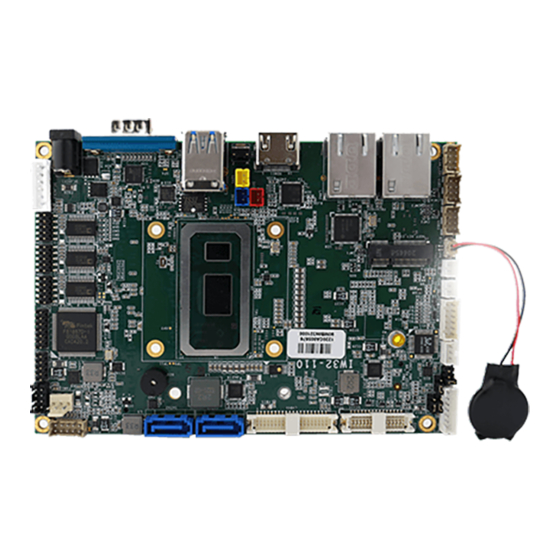
IW32 3.5" SBC
3.5" Form Factor SBC with Intel® Core™ i5 -8265U 1.6GHz Processor, up to 3.9 GHz,
HDMI, eDP, LVDS, USB 3.2 Gen 1, SATA III, and M.2 Interface
V110
User Manual
Document Version 1.0
Document Part No. 91711110110J
Please read these instructions carefully before using this product, and save this manual for future use.
Advertisement
Table of Contents

Related Manuals for Winmate IW32 3.5 SBC


Summary of Contents for Winmate IW32 3.5 SBC
- Page 1 IW32 3.5” SBC 3.5” Form Factor SBC with Intel® Core™ i5 -8265U 1.6GHz Processor, up to 3.9 GHz, HDMI, eDP, LVDS, USB 3.2 Gen 1, SATA III, and M.2 Interface V110 User Manual Document Version 1.0 Document Part No. 91711110110J Please read these instructions carefully before using this product, and save this manual for future use.
-
Page 2: Table Of Contents
IW32 3.5” SBC User Manual Contents PREFACE ................................4 ABOUT THIS USER MANUAL ..........................7 CHAPTER 1: GENERAL INFORMATION ........................8 1.1 I ................................9 NTRODUCTION 1.2 F ................................9 EATURES 1.3 M ..........................10 OTHERBOARD PECIFICATIONS 1.4 F ............................12 UNCTIONAL ESCRIPTION 1.5 P ............................ - Page 3 Preface 3.4 H ..........................60 OW TO NABLE ATCHDOG CHAPTER 4: DRIVER INSTALLATION ........................62 4.1 C ..............................63 HIPSET RIVER 4.2 G ..............................66 RAPHIC RIVER 4.3 M (ME) ..........................70 ANAGEMENT NGINE 4.4 A ..............................72 UDIO RIVER 4.5 E ..............................
-
Page 4: Preface
IW32 3.5” SBC User Manual Preface Copyright Notice No part of this document may be reproduced, copied, translated, or transmitted in any form or by any means, electronic or mechanical, for any purpose, without the prior written permission of the original manufacturer. Trademark Acknowledgement Brand and product names are trademarks or registered trademarks of their respective owners. - Page 5 Preface Customer Service We provide a service guide as below for any problem by the following steps: First, contact your distributor, sales representative, or our customer service center for technical support if you need additional assistance. You need to prepare the following information before you call: •...
- Page 6 IW32 3.5” SBC User Manual Safety Precautions CAUTION Always ground yourself to remove any static charge before touching the CPU card. Modern electronic devices are very sensitive to static electric charges. As a safety precaution, use a grounding wrist strap at all times. Place all electronic components in a static-dissipative surface or static-shielded bag when they are not in the chassis.
-
Page 7: About This User Manual
About This User Manual About This User Manual This User Manual provides information about using the IW32 3.5” SBC. The documentation set for the IW32 3.5” SBC provides information for specific user needs, and includes: • IW32 3.5” SBC User Manual – contains detailed description on how to use the motherboard, its components and features. -
Page 8: Chapter 1: General Information
IW32 3.5” SBC User Manual Chapter 1: General Information This chapter includes the IW32 3.5” SBC background information. 1.1 Introduction 1.2 Features 1.3 Motherboard Specifications 1.4 Functional Description 1.5 Physical Description... -
Page 9: Introduction
0BChapter 1: General Information 1.1 Introduction Thank you for choosing the IW32 3.5” SBC. This motherboard can be integrated with Intel® Core™ i5 -8265U 1.6GHz Processor, up to 3.9GHz, which offers a high performance computing platform with low power consumption. TheW32 3.5” SBC supports 260-pin 260 pin DDR4-2400 non-ECC SO-DIMM RAM, up to 32 GB. -
Page 10: Motherboard Specifications
IW32 3.5” SBC User Manual 1.3 Motherboard Specifications Model Name IW32 3.5” SBC Intel® Core™ i5 -8265U 1.6GHz Processor, up to 3.9 GHz System 260 pin DDR4-2400 non-ECC SO-DIMM RAM Memory (max to 32 GB) 1 x M.2 Key M Slot for M.2 2242 SSD, up to 512GB System Storage Optional M.2 2280 NVMe SSD, up to 4TB... - Page 11 0BChapter 1: General Information 1 x +5V for external power(Red) / 2-pin 1 x +3.3V for external power(Blue) / 2-pin 1 x Fan / 3-pin 1 x Brightness control /3-pin 1 x VR/Software brightness switch jumper/3-pin 1 x PWM/DA brightness switch jumper/3-pin 1 x 3.3V/5V PWM Level switch jumper/3-pin 1 x Panel Inverter / 7-pin 1 x Front Panel / 10-pin(2x5)
-
Page 12: Functional Description
IW32 3.5” SBC User Manual 1.4 Functional Description IW32 3.5” SBC Function block (V100) -
Page 13: Physical Description
0BChapter 1: General Information 1.5 Physical Description IW32 3.5” SBC Board Dimensions (V110) -
Page 14: Chapter 2: Hardware Installation
IW32 3.5” SBC User Manual Chapter 2: Hardware Installation This chapter provides information on how to use jumpers and connectors on the IW32 3.5” SBC. Be cautious while working with these modules. Carefully read the content of this chapter in order to avoid any damages. 2.1 Motherboard Components 2.2 Memory Module Installation 2.3 I/O Equipment Installation... -
Page 15: Motherboard Components
1BChapter 2: Hardware Installation 2.1 Motherboard Components 2.1.1 Component Side IW32 3.5” SBC Top Layer (Top View) - Page 16 IW32 3.5” SBC User Manual 2.1.2 Solder Side IW32 3.5” SBC Bottom Layer (Top View)
-
Page 17: Jumper Location
1BChapter 2: Hardware Installation 2.1.2 Jumper Location PCB Top Layer (Top View) -
Page 18: Memory Module (So-Dimm) Installation
IW32 3.5” SBC User Manual 2.2 Memory Module (SO-DIMM) Installation IW32 3.5” SBC has two 260-pin SODIMM slot. The socket supports DDR4. When installing the memory unit, please follow the steps below: 1. Firmly insert the SO-DIMM at an angle of about 30-degree into the slot. Align the SO-DIMM with the slot until it is fully inserted. -
Page 19: I/O Equipment Installation
1BChapter 2: Hardware Installation 2.3 I/O Equipment Installation 2.3.1 Power Input 12V DC in The IW32 3.5” SBC allows plugging 12V DC-IN jack on the board without another power module converter under power consumption by Intel® 9th Generation Core i7/i5/i3 Processor and H310 chipset. -
Page 20: Jumper Settings
IW32 3.5” SBC User Manual 2.4 Jumper Settings This section explains how to set jumpers for correct configuration of the motherboard. NOTE: A pair of needle nose pliers may be helpful when working with jumpers. If you have any doubts about the best hardware configuration for your application, contact your local distributor or sales representative before you make any changes. -
Page 21: Panel_Pwr_Sel1: Panel Power Voltage Select
1BChapter 2: Hardware Installation 2.4.1 PANEL_PWR_SEL1: Panel Power Voltage Select Pin № Name 1-2 (Default) +3.3V +12V 2.4.2 INV_VCC1: Backlight Power Voltage Select Pin № Name 1-2 (Default) +12V 2.4.3 BR_VR_CHIP1: Brightness PWM Control Select Pin № Name 1-2 (Default) VR Control Chipset Control 2.4.4 PWM_DC1: PWM/DC Mode Select... -
Page 22: Connector Description
IW32 3.5” SBC User Manual 2.5 Connector Description 2.5.1 Connector List Label Function Note BKLIGHT1 Backlight Power/Control RTC Battery COM1 D-SUB9 COM2.3.4 COM Port Power Jack 3P-2, 5-5, 5-B DCJACK1 DCJACK2 Power Jack A3963WV2-A2P Power Jack Wafer 1x4/ 2.0mm-X DCJACK3 DIDO1 Digital I/O Header Header/2*7p P:2.0mm SMT180°... -
Page 23: Connector Description
1BChapter 2: Hardware Installation 2.5.2 Connector Description 2.5.2.1 BKLIGHT1: Backlight Power/Control Pin № Signal Name BKL_PWR BKL_PWR BKL_PWR BKLIGHT1 BRIGHT BLON_5V Note: Please refer to INV_VCC1 settings to select Power Rating. 2.5.2.2 BT1: RTC Battery Pin № Signal Name Pin № Signal Name +.3.3V 2.5.2.3 COM1: D-SUB9... - Page 24 IW32 3.5” SBC User Manual 2.5.2.4 COM2/ COM3/ COM4: COM Port Pin № Signal Name Pin № Signal Name SOUT COM_PWR 2.5.2.5 DCJACK1: Power Jack Signal Name DC_IN DC_GND DCJACK1 2.5.2.6 DCJACK2: Power Jack Signal Name DC_IN DC_GND DCJACK2 2.5.2.7 DCJACK3: Power Jack Signal Name DC_IN DC_IN...
- Page 25 1BChapter 2: Hardware Installation 2.5.2.9 EDP1: eDP Connector Pin № Signal Name Pin № Signal Name EMB_AUXN SMB_DATA_MAIN EMB_AUXP SMB_DATA_CLK DP_TXN3_C +VCC_EDP_BKLT DP_TXP3_C +VCC_EDP_BKLT +VCC_EDP_BKLT DP_TXN2_C DP_TXP2_C DP_TXN1_C DP_TXP1_C LCDVDD GND- LCDVDD DP_TXN0_C LCDVDD DP_TXP0_C LCDVDD +VCC_EDP_BKLT 2.5.2.10 FAN1: CPU FAN Pin №...
- Page 26 IW32 3.5” SBC User Manual 2.5.2.11 HDMI1: HDMI Port Connector Use HDMI connector to connect the I IW32 3.5” SBC to an external monitor. Pin № Signal Name Pin № Signal Name TMDS_DATA2+ TMDS_DATA2- TMDS_DATA1+ HDMI TMDS_DATA1- TMDS_DATA0+ TMDS_DATA0- TMDS_CLOCK+ TMDS_CLOCK- DDC_CLOCK DDC_DATA...
- Page 27 1BChapter 2: Hardware Installation 2.5.2.12 LVDS1: LVDS Connector CN12 Pin № Signal Name Pin № Signal Name LCDVDD LVDS0_TX0_N LCDVDD LVDS0_TX0_P LCDVDD LVDS0_TX1_N LVDS0_TX1_P LVDS0_TX2_N LVDS0_TX2_P LVDS0_CLK_N LVDS0_CLK_P LVDS0_TX3_N LVDS0_TX3_P LVDS1_TX0_N LVDS1_TX0_P LVDS1_TX1_N LVDS1_TX1_P LVDS1_TX2_N LVDS1_TX2_P LVDS1_CLK_N LVDS1_CLK_P LVDS1_TX3_N LVDS1_TX3_P...
- Page 28 IW32 3.5” SBC User Manual 2.5.2.13 LAN1/ LAN2: RJ45 The IW32 3.5” SBC has two Ethernet connectors located on the front. Ethernet ports provide a standard RJ45 10/100/1000 Mbps jack connector with LED indicators on the front side to show its Active/ Link status and Speed status.
- Page 29 1BChapter 2: Hardware Installation 2.5.2.18 SATA1, SATA2: SATA Connector Signal Name SATA_TX- SATA_TX+ SATA1, SATA2 SATA_RX- SATA_RX+ 2.5.2.19 Left: SPK_L Right: SPK_R: Speaker LEFT RIGHT 2.5.2.20 USB1: USB3.2 Connector * 2 Pin № Signal Name Pin № Signal Name USB_D- USB_D+ STDA_SSRX- STDA_SSRX+...
- Page 30 IW32 3.5” SBC User Manual 2.5.2.23 Power Output Wafer 12V (Yellow Wafer) Signal Name +12V 5V (Red Wafer) Signal Name 3.3V (Blue Wafer) Signal Name +3.3V...
-
Page 31: Chapter 3: Insyde H20 Bios Setup
Chapter 3: Insyde H20 BIOS Setup Chapter 3: Insyde H20 BIOS Setup This chapter describes the different settings available in the INSYDE BIOS that comes with the board. This chapter offers information on the Award BIOS installation utility. 4.1 How and When to Use BIOS Setup 4.2 BIOS Functions 4.3 Using Recovery Wizard to Restore Computer 4.4 How to Enable Watchdog... -
Page 32: How And When To Use Bios Setup
IW32 3.5” SBC User Manual 3.1 How and When to Use BIOS Setup To enter the BIOS setup, you need to connect an external USB keyboard, external monitor and press Del key when the prompt appears on the screen during start up. The prompt screen shows only few seconds so need press Del key quickly. -
Page 33: Bios Functions
Chapter 3: Insyde H20 BIOS Setup 3.2 BIOS Functions 3.2.1 Main Menu The Main menu displays the basic information about yoursystem including BIOS version, processor RC version, system language, time, and date. When you enter BIOS setup, the first menu that appears on the screen is the main menu.It contains the system information including BIOS version, processor RC version, system language, time, and date. -
Page 34: Advanced
IW32 3.5” SBC User Manual 3.2.2 Advanced Select the Advanced Tab from the setup menu to enter the advanced BIOS setup screen. You can select any of the items on the left frame of the screen to go to the sub menu for the item, such as CPU Configuration. - Page 35 Chapter 3: Insyde H20 BIOS Setup BIOS Setting Description Setting Option Effect Configures Trusted Enter Opens Configuration Computing parameters submenu Power & Configures Power & Enter Opens Performance Performance parameters submenu System Agent Configures System Agent Enter Opens Configuration Configuration parameters submenu PCH-OI Configures...
- Page 36 IW32 3.5” SBC User Manual BIOS Setting Description Setting Option Effect Intel (VMX) Enable disable Enable/Disable When enabled, a Virtualization Intel Virtualization can utilize Technology Technology. additional hardware capabilities provided Vanderpool Technology. Active Processor Number of core to AII / 1 / 2/ 3 Select number of Cores enable...
- Page 37 Chapter 3: Insyde H20 BIOS Setup 3.2.2.2 F81886A Configuration...
- Page 38 IW32 3.5” SBC User Manual 3.2.2.3 GPIO Configuration...
- Page 39 Chapter 3: Insyde H20 BIOS Setup...
- Page 40 IW32 3.5” SBC User Manual 3.2.2.4 Hardware Monitor...
- Page 41 Chapter 3: Insyde H20 BIOS Setup 3.2.2.5 PCH-IO Configuration BIOS Setting Description Setting Option Effect Express PCI Express clock gating Enter Opens sub-menu Configuration enable/disable for each root port. SATA Enable/ Disable SATA Enter Opens sub-menu Configuratuion device USB Configuration Selectively enable/ Enter...
- Page 42 IW32 3.5” SBC User Manual 3.2.2.6 PCI Express Configuration...
- Page 43 Chapter 3: Insyde H20 BIOS Setup...
- Page 44 IW32 3.5” SBC User Manual 3.2.2.7 SATA and RST Configuration...
- Page 45 Chapter 3: Insyde H20 BIOS Setup 3.2.2.8 USB Configuration...
- Page 46 IW32 3.5” SBC User Manual 3.2.2.9 ME Firmware Configuration...
- Page 47 Chapter 3: Insyde H20 BIOS Setup 3.2.2.10 Power & Performance BIOS Setting Description Setting Option Effect CPU – Power Configure – Enter Opens sub-menu Management Power Management Control parameters...
- Page 48 IW32 3.5” SBC User Manual...
- Page 49 Chapter 3: Insyde H20 BIOS Setup BIOS Setting Description Setting Option Effect Boot Configure Boot -Max non-turbo Select the performance Performance Performance Mode performance state that the BIOS will set Mode parameters -Max battery starting from reset vector -Turbo Performance Intel Configure Intel...
- Page 50 IW32 3.5” SBC User Manual 3.2.2.11 System Agent (SA) Configuration BIOS Setting Description Setting Option Effect Graphics Configure Graphics Enter Opens sub-menu Configuration Configuration parameters Vt-d Intel® Virtualization Enabled Vt-d capability Technology Disabled Directed I/O...
- Page 51 Chapter 3: Insyde H20 BIOS Setup 3.2.2.11.1 Graphics Configuration BIOS Setting Description Setting Effect Option Internal Graphics Internal Graphics Auto Keep IGFX enabled based on settings Enabled the setup options Disabled Aperture Size Select 128MB Select the aperture size aperture size 256MB Note: Above 4MB MMIO BIOS 512MB...
- Page 52 IW32 3.5” SBC User Manual 3.2.2.11.2 Vt-d BIOS Setting Description Setting Option Effect Vt-d Intel® Enabled Vt-d capability Virtualization Disabled Technology Directed I/O...
-
Page 53: Boot
Chapter 3: Insyde H20 BIOS Setup 3.2.3 Boot BIOS Setting Description Setting Effect Option Boot Type Boot Type UEFI Boot Select boot type to Dual type, configuration Type Legacy type or UEFI type Quick Boot Quick Boot Enabled Allows InsydeH20 to skip certain configuration Disabled tests while booting. - Page 54 IW32 3.5” SBC User Manual...
- Page 55 Chapter 3: Insyde H20 BIOS Setup 3.2.3.1 Boot Type Order BIOS Setting Description Setting Option Effect Hard Disk Type Hard Disk Type Enter Opens Sub-menu configuration Others Other Enter Opens Sub-menu configuration...
-
Page 56: Security
IW32 3.5” SBC User Manual 3.2.3.1.1 Others 3.2.4 Security... -
Page 57: Power
Chapter 3: Insyde H20 BIOS Setup BIOS Setting Description Setting Option Effect TrEE Protocol Version Choose TrEE TrEE Protovol Protocol Version Version: 1.0 or 1.1 TPM Availability Availability Available When hidden don’t configuration Hidden exposes TPM to 0 TPM Operation Operation Select one of the configuration... -
Page 58: Exit
IW32 3.5” SBC User Manual BIOS Setting Description Setting Option Effect ACPI S3 ACPI Disabled Enable/ Disable configuration Enabled ACPI S1/S3 Sleep state Auto Wake on S5 Auto Wake on S5 Disabled Auto Wake on S5, configuration By Every Day by Day or Month By Every Month or fixed time of... -
Page 59: Using Recovery Wizard To Restore Computer
Chapter 3: Insyde H20 BIOS Setup 3.3 Using Recovery Wizard to Restore Computer Note: Before starting the recovery process, make sure to backup all user data. The data will be lost after the recovery process. Important: Before starting the recovery process, remove any expansion card. -
Page 60: How To Enable Watchdog
OS initialize process 3.4 How to Enable Watchdog To enable Watchdog, you need to download Winmate Watchdog utility. Find more information on Watchdog in “Watchdog Guide” that you can download from Winmate Download Center or File Share. Refer to the User Manual for more details. - Page 61 Chapter 3: Insyde H20 BIOS Setup 3. In Watchdog utility window set countdown time and periodically feed time, or disable watchdog. Setting Description The system automaticity restarts when this countdown Watchdog Countdown Time time reaches zero. Default: 10 min To set a cycle time to automatically reset watchdog Periodically Feed Time timer.
-
Page 62: Chapter 4: Driver Installation
IW32 3.5” SBC User Manual Chapter 4: Driver Installation This chapter contains driver installation guide. Follow the instructions below to complete the installation. You will quickly complete the installation. This chapter provides instructions on how to install drivers on the IW32 3.5” SBC. 4.1 Chipset Driver Installation 4.2 Graphic Driver Installation 4.3 Management Engine (ME) -
Page 63: Chipset Driver
IW32 3.5” SBC User Manual 4.1 Chipset Driver Follow instructions below to install Chipset driver. 1. Open the Driver CD (included in the package) and select Chipset driver. - Page 64 IW32 3.5” SBC User Manual 2. Installation window will pop up, select Next. 3. Select Accept to agree with the terms of license agreement.
- Page 65 2BChapter 4: Driver Installation 4. Check the ReadMe file information, select Install to continue. 5. Wait for the driver to be installed. When installation completed, select Restart Now to restart your computer.
-
Page 66: Graphic Driver
IW32 3.5” SBC User Manual 4.2 Graphic Driver Follow instructions below to install Graphic driver. 1. Open the Driver CD (included in the package) and select Graphic driver. 2. Installation window will pop up, select Next. - Page 67 2BChapter 4: Driver Installation 3. Select Accept to agree with the terms of license agreement.
- Page 68 IW32 3.5” SBC User Manual 4. Check the ReadMe file information, select Next to continue. 5. Wait for the driver to be installed.
- Page 69 2BChapter 4: Driver Installation 6. Select Next to continue. 7. After installation is completed, select “Yes, I want to restart this computer now”, and click Finish.
-
Page 70: Management Engine (Me)
IW32 3.5” SBC User Manual 4.3 Management Engine (ME) Follow instructions below to install Management Engine (ME) . 1. Open the Driver CD (included in the package) and select ME driver. 2. Select Next to start the installation. - Page 71 2BChapter 4: Driver Installation 3. Select Next to agree with the terms of license agreement. 4. Wait for the driver to be installed.
-
Page 72: Audio Driver
IW32 3.5” SBC User Manual 5. When installation completed, select Finish complete installation. 4.4 Audio Driver Follow instructions below to install Audio driver. 1. Open the Driver CD (included in the package) and select Audio driver. - Page 73 2BChapter 4: Driver Installation 2. Select Next to continue. 3. When installation completed, select Finish complete installation.
-
Page 74: Ethernet Driver
IW32 3.5” SBC User Manual 4.5 Ethernet Driver Follow instructions below to install LAN driver. 1. Open the Driver CD (included in the package) and select LAN driver. 2. When compression is complete, select Next. - Page 75 2BChapter 4: Driver Installation 3. Read the license agreement, and then select Next. 4. System displays the installed packages, select Next.
- Page 76 IW32 3.5” SBC User Manual 5. Confirm the installation, select Install to start the installation. 6. When installation is completed, select Finish to close the window.
-
Page 77: Watchdog Driver
2BChapter 4: Driver Installation 4.6 Watchdog Driver For more details about Winmate Watchdog, please download Watchdog Guide from Winmate Downloads Center: http://dc.winmate.com.tw/_downloadCenter/2017/Embedded%20Computing/Watchdog%20Guide_ IB_IH_IV_IK.pdf Follow instructions below to install Watchdog driver. 1. Type “cmd” in the run box then the cmd.exe will appear in programs. - Page 78 IW32 3.5” SBC User Manual 3. When Windows Security dialog appear, select install to continue the Installation. 4. Wait for installation to complete. When installation is complete, press any key to close.
- Page 79 2BChapter 4: Driver Installation 5. Open the Driver CD (included in the package) and select Watchdog AP. 6. Select Next.
- Page 80 IW32 3.5” SBC User Manual 7. The installed storage location is displayed, select Next to continue. 8. Select Next to start the installation.
-
Page 81: Digital Io Driver Installation
2BChapter 4: Driver Installation 9. When installation is completed, select Finish to close the window. 4.7 Digital IO Driver Installation For more details about Winmate Watchdog, please download Digital IO Guide from Winmate Downloads Center: Follow instructions below to install Digital IO river. - Page 82 IW32 3.5” SBC User Manual 3. Open the Driver CD (included in the package) and select Digital IO driver. 4. When Windows Security dialog appear, select install to continue the Installation. 5. Wait for installation to complete. When installation is complete, press any key to close.
- Page 83 2BChapter 4: Driver Installation 6. Open the Driver CD (included in the package) and select Digital IO AP.
-
Page 84: Chapter 5: Technical Support
IW32 3.5” SBC User Manual Chapter 5: Technical Support This chapter includes the directory for technical support. Free technical support is available from our engineers every business day. We are always ready to give advice on application requirements or specific information on the installation and operation of any of our products. -
Page 85: Drivers
3BChapter 5: Technical Support 5.1 Drivers The list of drivers available for IW32 3.5” SBC: Item Driver Chipset Driver Graphic Driver ME Driver Audio Driver Ethernet Driver Watchdog Driver/AP Digital IO Driver/AP To find the Drivers, please refer to the Driver CD that comes in the package or contact us. -
Page 86: Software Development Kit (Sdk)
IW32 3.5” SBC User Manual 5.2 Software Development Kit (SDK) The list of SDK available for IW32 3.5” SBC: Item File Type Description Watchdog SDK Digital IO SDK To find the SDK, please refer to the Driver CD that comes in the package or contact... - Page 88 Winmate Inc. 9F, No.111-6, Shing-De Rd., San-Chung District, New Taipei City 24158, Taiwan, R.O.C www.winmate.com Copyright © Winmate Inc. All rights reserved.
Need help?
Do you have a question about the IW32 3.5 SBC and is the answer not in the manual?
Questions and answers