Table of Contents
Advertisement
Quick Links
Download this manual
See also:
User Manual
Advertisement
Table of Contents

Related Manuals for Winmate IV70


Summary of Contents for Winmate IV70
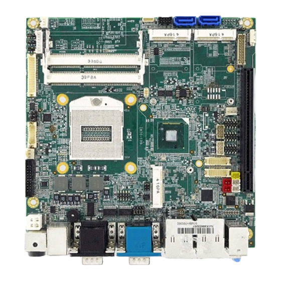
- Page 1 IV70 Motherboard ® PGA988 Mini-ITX Fan SBC w/ Intel Generation Core™i7/i5 Processor, VGA/ LVDS/DVI/HDMI, Dual LAN, 4xUSB 3.0, PCIe x16 USER MANUAL Version 1.0 WinMate Communication INC...
-
Page 2: Fcc Statement
CPU card. Modern electronic devices are very sensitive to static electric charges. As a safety precaution, use a grounding wrist strap at all times. Place all electronic components in a static-dissipative surface or static-shielded bag when they are not in the chassis. IV70 Motherboard User Manual... -
Page 3: Copyright Notice
(e. g., with A for October, B for November and C for December). For example, the serial number 1W07Axxxxxxxx means October of year 2007. IV70 Motherboard User Manual... -
Page 4: Packing List
Before using this Motherboard, please make sure that all the items listed below are present in your package: IV70 Motherboard IV70 SBC User Manual HDD SATA Cable User’s Manual & Driver CD If any of these items are missing or damaged, contact your distributor or sales representative immediately. - Page 5 F. The equipment has obvious signs of breakage. 15. Do not leave this equipment in an uncontrolled environment where the storage temperature is below -20° C (-4°F) or above 60° C (140° F). It may damage the equipment. IV70 Motherboard User Manual...
- Page 6 Revision History Version Date Note Author 2012.12.07 Initial Draft Henry Hsu IV70 Motherboard User Manual...
-
Page 7: Table Of Contents
................. 46 DVANCED ETTING 7.4 C ................64 HIPSET ETTING 7.5 B ....................71 ..................73 ECURITY & E ................. 74 8 SERVICES/ UPDATES ............... 75 8.1 IV70 O ..............75 FFICIAL WEBSITE ............... 75 OMPANY INFORMATION IV70 Motherboard User Manual... -
Page 8: Chapter 1 General Information
General Information This chapter includes IV70 Motherboard background information. Sections include: Introduction Feature Motherboard Specification Function Block Board Dimensions IV70 Motherboard User Manual... - Page 9 SATA SSD), two SATA connectors(one SATAIII), and eight Hi-Speed USB connectors.(four USB3.0 in I/O side) Thus, IV70 SBC is designed to satisfy most of the applications in the industrial computer market, such as Gaming, POS, KIOSK, Industrial Automation, and Programmable Control System.
-
Page 10: Motherboard Specifications
1 x PCIEx16, 1 x PCIEx4, 2 x Mini-PCIE, 1 x mSATA SSD Form Factor Mini-ITX Dimensions 170mm x 170mm Operating temperature: 0 deg. C to 60 deg. C Mechanical & Operating Humidity: 30 ~ 90% Relative humidity, non-condensing environmental Certification: CE, FCC, RoHS IV70 Motherboard User Manual... -
Page 11: Function Block
Function Block IV70 Motherboard User Manual... -
Page 12: Board Dimensions
Board dimensions IV70 Motherboard User Manual... -
Page 13: Chapter 2 Installations
Installations This chapter provides information on how to use the jumps and connectors on IV70 Motherboard. The Sections include: Memory Module Installation I / O Equipment Installation Setting the Jumpers Connectors on IV70 Motherboard IV70 Motherboard User Manual... -
Page 14: Memory Module(Sodimm)Installation
Chapter 2 Installations 2.1 Memory Module(SODIMM)Installation The IV70 Motherboard provides two 204-pin SODIMM slot. The socket supports up to 16GB DDR3 1333/1600 SDRAM. When installing the Memory device, please follow the steps below: Step.1. Firmly insert the SODIMM at an angle into its slot. Align the SODIMM on the slot such that the notch on the SODIMM matches the break on the slot. - Page 15 Whatever, you should install the device driver before you use the device. 2.2.7 Audio Jack ( Pin-header) The Audio 5.1 channel capabilities are provided by a Realtek ALC886 chipset supporting digital audio outputs. The audio interface includes Mic-in,: line-in and line-out. IV70 Motherboard User Manual...
-
Page 16: Jumpers And Connectors
COM3 USB3.0 Audio Jack SATAIII front SODIMM2 mSATA SODIMM1 panel SATAII JP10 MiniPCIe HDMI LVDS JP9, JP8 Inverter PCIEx16 JP7, JP6 NB_FAN1 CPU_FAN1 USB2 JP4, JP3 USB1 PCIEx4 COM2 COM5 COM6 LPT1 CN8,CN9 ATX12V J1,J2 MiniPCIe IV70 Motherboard User Manual... -
Page 17: Jumper Setting
VR/Software 3x1 header , pitch 2.0mm PWM/DA 3x1 header , pitch 2.0mm Back Light PWR 3x1 header , pitch 2.5mm PWM Level 3x1 header , pitch 2.0mm JP10 LVDS PWR Selector 2x3 header , pitch 2.5mm IV70 Motherboard User Manual... - Page 18 Clear CMOS. Users remember to setting jumper back to Normal before turning on the power supply. Default: 2 short 3. Clear CMOS Normal Pin No. Functions 1 Short 2 Clear CMOS 2 Short 3 Normal 2.4.3 JP6 : Brightness Control(VR/Software) 2.4.4 JP7 : Brightness Control(DC/PWM) IV70 Motherboard User Manual...
- Page 19 2.4.7 JP10: LCD Panel Voltage Select JP10 can be configured to operate in 3.3Volts / 5Volts / 12Volts mode. 3.3Volts 5Volts 12Volts Pin No. Functions 1 Short 2 3.3Volts Selected 3 Short 4 5Volts Selected 5 Short 6 12Volts Selected IV70 Motherboard User Manual...
-
Page 20: Connectors And Pin Assignment
Mini-PCIE Half size CN18 Mini-PCIE Full size SIM card connector 6 pin Header DVI FFC 18 pin FFC HDMI FFC 18 pin FFC ATX12V DC Connector 2x2 Pin Connecter LPT1 LPT Connector 10x2 header ,pitch 2.54mm IV70 Motherboard User Manual... - Page 21 LVDS_TXUCKP LVDS_TXU3N LVDS_TXU3P 2.5.2 CN17: Digital Panel Backlight Brightness Control Pin No. SYMBOL VCC(5V) Black Light Control 2.5.3 CN16: Digital Panel Backlight Control Pin No. SYMBOL +12V +12V +12V Black Light Control Black Light EN 5V IV70 Motherboard User Manual...
- Page 22 The serial port COM1, which is option for RS232 / RS422 / RS485, is the Winbond I/O serial port. COM1 Up: 9(Male) Down: 15(Female) Pin No. SYMBOL Pin No. SYMBOL DCD4/485TXRX- SRD4/485TXRX+ STD4/422RX+ DTR4/422RX- NDSRA NRTSA NCTSA NRIA DDC_DATA CRT_HS CRT_VS DDC_CLK IV70 Motherboard User Manual...
- Page 23 FK_NDSR2 FK_NRTS1 FK_NRTS2 FK_NCTS1 FK_NCTS2 FK_NRI1 FK_NRI2 COM3 2.5.8 AUDIO401: Audio Jack ( Pin-header ) Color Signal Blue Line In Green Line Out Pink Microphone In Pin-Header C0~C4 Line in B1~B4 Line out A1~A4 Mic in IV70 Motherboard User Manual...
- Page 24 SYMBOL USBVCC USBVCC USB_DATA1- USB_DATA0- USB_DATA1+ USB_DATA0+ 2.5.10 FAN1_NB/FAN2_CPU: FAN CONNECTOR FAN1_NB FAN2_CPU 2.5.11 PANEL: Front Panel System Function Connector SYMBOL SYMBOL HD_LED+ PW_LED+ HD_LED- PW_LED- RT_BT1 PW_BT1 RT_BT2 PW_BT2 5VSB RSEV 2.5.12 J1/J2: Front Audio IV70 Motherboard User Manual...
- Page 25 2.5.13 5V/12V/HDD PWR: External Power Yellow HDD PWR 2.5.14 PWIN1: DC Jack ( +12V) / Input 2.5.15 ATX_PWR / Input: 12V DC Connector SYMBOL Ground Ground +12V +12V 2.5.17 : CN7: Digital I/O Connector SYMBOL SYMBOL Out1 Out3 Out0 Out2 IV70 Motherboard User Manual...
- Page 26 2.5.18 : CN22:SIM card connector CN22 Pin Number Signal Name VREG_USIM MSM_USIM_RESET MSM_USIM_CLK MSM_USIM_VPP MSM_USIM_DATA 2.5.19 : Parallel Port Box Header LPT1 IV70 Motherboard User Manual...
- Page 27 : CN2: Half Size Mini-PCIE slot Pin Number Signal Name Pin Number Signal Name VCC3_MINIPCIE1 PCIE_WAKE# +V1.5S VREG_USIM CLK_SLOT4_OE# CLK_PCIE_SLOT4_N CLK_PCIE_SLOT4_P WLAN-RFON2 BUF_PLT_RST2# +V3.3A PCIE_RXN3_SLOT4 PCIE_RXP3_SLOT4 +V1.5S SMB_CLK SMB_DATA PCIE_TXN3_SLOT4 PCIE_TXP3_SLOT4 USB_PN5 USB_PP5 VCC3_MINIPCIE1 VCC3_MINIPCIE1 VCC3_MINIPCIE1 IV70 Motherboard User Manual...
- Page 28 2.5.20 : CN3: Full Size 3.5G Module Pin Number Signal Name Pin Number Signal Name VCC3_MINIPCIE1 PCIE_WAKE# +V1.5S VREG_USIM CLK_SLOT3_OE# MSM_USIM_DATA MSM_USIM_CLK CLK_PCIE_SLOT3_N MSM_USIM_RESET CLK_PCIE_SLOT3_P MSM_USIM_VPP WLAN-RFON1 BUF_PLT_RST2# +V3.3A PCIE_RXN3_SLOT3 PCIE_RXP3_SLOT3 +V1.5S SMB_CLK SMB_DATA PCIE_TXN3_SLOT3 PCIE_TXP3_SLOT3 USB_PN4 USB_PP4 VCC3_MINIPCIE1 VCC3_MINIPCIE1 VCC3_MINIPCIE1 IV70 Motherboard User Manual...
-
Page 29: Chapter 3 Graphic Driver Installation
Graphic Driver Installation This chapter offers information on the chipset software Installation utility Installation of Graphic Driver Panel Resolution Setting IV70 Motherboard User Manual... -
Page 30: Standard Cmos Feature
(VGA compatible). Follow the instructions below to complete the installation. You will quickly complete the installation. Step.1. Insert the CD that comes with the Motherboard. Open the file document “Graphic Driver “. Step.2. Click on “setup” to execute the setup. IV70 Motherboard User Manual... - Page 31 Step.3. Click on “Next “ to install Driver. Step.4. Click on “Yes “ to agree License. IV70 Motherboard User Manual...
- Page 32 Step.5. Click on “Next “ to install Driver. Step.6. Click on “Next “ to install Driver. IV70 Motherboard User Manual...
- Page 33 Step.7. Click on “Yes, I want to restart this computer now“ to go on. IV70 Motherboard User Manual...
-
Page 34: Panel Resolution Setting
3.2 Panel Resolution Setting Step.1. Right-click the desktop, and then click Properties. Step.2. In the Display Properties dialog box, click the Settings tab. Step.3. Click on “Monitor”. IV70 Motherboard User Manual... - Page 35 Step.4. Click on “Hide modes that this monitor cannot display” to remove this option. Step.5. Click on “Setting”, then could choose 32bit color qualify. IV70 Motherboard User Manual...
-
Page 36: Chapter 4 Chipset Driver Installation
Chipset Driver Installation This chapter offers information on the chipset software Installation utility Installation of Chipset Driver Further information IV70 Motherboard User Manual... -
Page 37: Standard Cmos Features
Chapter 4 Chipset Driver Installation 4.1 Standard CMOS Features Setp.1. Insert the CD that comes with the motherboard. Open the file document “Chipset Driver”. Setp.2. Click on “infinst_auto.exe“ to install driver. IV70 Motherboard User Manual... - Page 38 Click on “Yes “ to agree License Setp.3. Setp.4. Click on “Next“ to install driver. IV70 Motherboard User Manual...
- Page 39 Setp.5. Click on “Next“ to install driver. Step.7. Click on “Yes, I want to restart this computer now“ to go on. IV70 Motherboard User Manual...
-
Page 40: Chapter 5 Ethernet Driver Installation
Ethernet Driver Installation This chapter offers information on the Ethernet software installation utility. Sections include: Introduction Installation of Ethernet Driver IV70 Motherboard User Manual... - Page 41 Broadcom BCM57780 Gigabit Ethernet controller LAN drivers. You will quickly complete the installation. Step.1. Right-click the desktop, and then click Properties. Step.2. In the Other device dialog box, click the Settings tab. IV70 Motherboard User Manual...
- Page 42 Step.2 Click on “Update Driver” to execute the setup. Click on “Browse my computer for driver software“ to install driver. Step.4. IV70 Motherboard User Manual...
- Page 43 Step.5. Choose the path to install driver. Click on “Close“ and go on. Setp.6. IV70 Motherboard User Manual...
-
Page 44: Chapter 6 Audio Driver Installation
Audio Driver Installation This chapter offers information on the Audio software installation utility. Sections include: Introduction Installation of Audio Driver IV70 Motherboard User Manual... - Page 45 Realtek ALC655 Audio drivers. You will quickly complete the installation. Step.1. Insert the CD that comes with the motherboard. Open the file document “alc655_driver” and click on “Vista_Win7_R260.exe” to execute the setup. IV70 Motherboard User Manual...
- Page 46 Step.2. Click on “Yes“ to install driver. Click on “Yes, I want to restart my computer now” to finish installation. Step.3. IV70 Motherboard User Manual...
-
Page 47: Driver Installation
Fintek COM Port Driver Installation This chapter describes the step by step method to install the Fintek COM port driver. IV70 Motherboard User Manual... - Page 48 STEP 4.Check driver install success. Before the update or update fail. After the update and update success. STEP 5.You will need to restart your computer for driver install success. Type in this command from the Run menu: C:\Windows\System32\UserAccountControlSettings.exe IV70 Motherboard User Manual...
- Page 49 To turn off UAC, move the slider to the Never notify position, and then click OK. If you're prompted for an administrator password or confirmation, type the password or provide confirmation. IV70 Motherboard User Manual...
- Page 50 To turn UAC back on, move the slider to choose when you want to be notified, and then click OK. If you're prompted for an administrator password or confirmation, type the password or provide confirmation. You will need to restart your computer for UAC to be turned off. IV70 Motherboard User Manual...
- Page 51 Advanced Chipset Features Integrated Peripherals Power Management Setup PC Health Status Load Fail-Safe Defaults Load Optimized Defaults Set Supervisor/User Password Save & Exit Setup Exit Without Saving IV70 Motherboard User Manual...
-
Page 52: Chapter 7 Ami Bios Setup
When you first enter the BIOS Setup Utility, you will enter the Main setup screen. You can always return to the Main setup screen by selecting the Main tab. There are two Main Setup options. They are described in this section. The Main BIOS Setup screen is shown below. IV70 Motherboard User Manual... - Page 53 The right frame displays the key leg- end. Above the key legend is an area reserved for a text message. When an option is selected in the left frame, it is highlighted in white. Often a text message will accompany it. IV70 Motherboard User Manual...
-
Page 54: Advanced Setting
7.3 Advanced Setting PCI Subsystem Settings IV70 Motherboard User Manual... - Page 55 Value to be programmed into PCI Latency Timer Register.(32~248) VGA Palette Snoop Enables or Disables VGA palette registers snooping PERR# Generation Enables or Disables PCI device to generate PERR# SERR# Generation Enables or Disables PCI device to generate SERR# IV70 Motherboard User Manual...
-
Page 56: Pci Express Settings
Defines number of microseconds software will wait before polling ‘Link Training” bit in link status register. Value range from 10 to 1000 uS Unpopulated Links In order to save power, software will disable unpopulated PCI express links, if this option set to ‘Disabled’ IV70 Motherboard User Manual... - Page 57 OS. ACPI Sleep State Select the ACPI sleep state the system will enter, when the SUSPEND button is pressed. Lock Legacy Resources Enables or Disables lock of legacy resources. IV70 Motherboard User Manual...
- Page 58 Trusted Computing Security Device Support Enable or disable BIOS support for security device. IV70 Motherboard User Manual...
-
Page 59: Cpu Configuration
To turn on/off prefetching of adjacent cache lines. TCC Activation offset Offset from the factory TCC activation temperature. Primary Plane Current value The maximum instantaneous current allow for Primary plane. Secondary Plane Current value The maximum instantaneous current allow for Second plane. IV70 Motherboard User Manual... -
Page 60: Sata Configuration
This item allows users to select mode of SATA controller(s). SATA Test Mode This item allows users to enable or disable the Test mode. Aggressive LPM Support Enable PCH to aggressively enter link power state. Software Feature Mask Configuration IV70 Motherboard User Manual... -
Page 61: Thermal Configuration
This value sets the TC1 value for the ACPI passive cooling formula. Passive TC2 value This value sets the TC2 value for the ACPI passive cooling formula. Passive TSP value This value sets the TSP value for the ACPI passive cooling formula. IV70 Motherboard User Manual... - Page 62 Intel® Rapid start technology This item allows users to enable or disable Intel rapid start technology. PCH-FW Configuration This item allows users to enable or disable Me FW image re-flash function. IV70 Motherboard User Manual...
-
Page 63: Acoustic Management Configuration
This item allows users to enable or disable Intel AT in bios for testing only. Intel® Anti-theft Technology Rec Set the number of times recovery attemped will be allowed. Acoustic Management Configuration Option to enable or disable automatic acoustic management. IV70 Motherboard User Manual... -
Page 64: Usb Configuration
Time-out value for control, bulk, and interrupt transfers. Device reset time-out USB mass storage device starts unit command time-out. Device power-up delay Maximum time the device will take before it properly report itself to the host controller. IV70 Motherboard User Manual... -
Page 65: Smart Settings
Enable or disable Run SMART Self test on all HDDs during Post F81865 Super IO Configuration Serial Port Configuration Set Parameters of Serial Ports. User can Enable/Disable the serial port and Select an optimal settings for the Super IO Device. IV70 Motherboard User Manual... - Page 66 This field enables or disables the smart fan feature. At a certain temperature, the fan starts turning. Once the temperature drops to a certain level, it stops turning again. Platform Misc Configuration PCI Express Native Support Enable/Disable. This feature is only available in vista. IV70 Motherboard User Manual...
- Page 67 Intel Smart Connect Technology Enable/Disable ISCT configuration. Serial Port Console Redirection Console Redirection This item allows users to enable or disable console redirection for Microsoft Windows Emergency Management Services (EMS). IV70 Motherboard User Manual...
-
Page 68: Terminal Type
Disabled: all clocks turned on. Enabled: clocks for empty PCI/PCIe slots will be turned off to save power. Lock ICC registers All registers: all ICC registers will be locked. Static only: only static ICC registers will be locked. IV70 Motherboard User Manual... - Page 69 Intel RC Drivers Version Detail IV70 Motherboard User Manual...
-
Page 70: Cpu Ppm Configuration
Time window which the long duration power is maintained. Short duration power limit This item allows users to enable or disable CPU TDP lock function. ACPI T state This item allows users to enable or disable ACPI T state function. IV70 Motherboard User Manual... - Page 71 Sandybridge DTS Configuration CPU DTS This item allows users to select the ACPI thermal management uses EC reported temperature value function. IV70 Motherboard User Manual...
-
Page 72: Chipset Setting
High Precision Timer Enables or disables the high precision timer. SLP_S4 Assertion Width This item allows users to set a delay of sorts. Restore AC Power Loss This item allows users to select off, on and last state. IV70 Motherboard User Manual... -
Page 73: Pci Express Configuration
PCIe-USB glitch W/A for bad USB device connected behind PCIE/PEG port. Subtractive Decode Enable or disable PCI Express subtractive decode. PCI Express Root Port 1~7 This item allows users to enable or disable the PCI Express Root Port. IV70 Motherboard User Manual... - Page 74 XHCI Mode This item allows user to enable or disable XHCI Mode. EHCI 1/2 Enables or disables the EHCI controller. USB Ports pre-port Disable Control This item allows users to enable or disable each USB port individually. IV70 Motherboard User Manual...
-
Page 75: Pch Azalia Configuration
PCH Azalia Configuration Azalia This item allows user to enable or disable azalea device. BIOS Security Configuration Enable or disable SMI/BIOS/GPIO/BIOS interface/RTC RAM Lock. IV70 Motherboard User Manual... - Page 76 System Agent Bridge Name This item allows users to enable or disable VT-d. Graphic Configuration IV70 Motherboard User Manual...
-
Page 77: Nb Pcie Configuration
NB PCIe Configuration PEG0 - Gen x Select PEG0 speed. Enable PEG This item allows users to enable or disable PEG always. PEG Sampler Calibrate This item allows users to enable or disable PEG sampler calibrate function. IV70 Motherboard User Manual... - Page 78 Memory Information IV70 Motherboard User Manual...
-
Page 79: Boot
INT19 Trap Response This item allows option ROMs to trap interrupt 19 Boot Option #1、#2、#3 Selects the boot sequence of the device. Hard Drive BBS Priorities Set the order of the legacy devices in this group. IV70 Motherboard User Manual... -
Page 80: Csm Parameters
Controls the execution of UEFI and legacy storage OpROM. policy Launch Video OpROM Controls the execution of UEFI and legacy video OpROM. policy Other PCI device ROM For PCI device than Network, mass storage or video defines which OpROM to priority launch. IV70 Motherboard User Manual... -
Page 81: Security
This section allows you to configure and improve your system and llows you to set up some system features according to your preference. Administrator Password Set Setup Administrator Password. User Password Set User Password. HDD 0: FUJITSU MHY2 Sets the HDD password. IV70 Motherboard User Manual... -
Page 82: Save & Exit
Save as User Defaults Save the changes done so far as User Defaults. Restore User Defaults Restore the User Defaults to all the setup options. Reset System with ME disable Mode ME will run into the temporary disable mode. IV70 Motherboard User Manual... -
Page 83: Services/ Updates
8 Services/ Updates 8.1 IV70 Official website The relevant information about IV70 Products including the latest news and downloads will be presented in the website below: http://www.winmate.com.tw/PanelPc/PPcQuery_tab.asp?Type=B01080119 Please go there to obtain further details of IV70 Products. 8.2 Company information Winmate Communication Inc.
Need help?
Do you have a question about the IV70 and is the answer not in the manual?
Questions and answers