Table of Contents
Advertisement
Quick Links
IF70 Mini-ITX SBC
Mini-ITX SBC with Intel® 9th Gen. Core i3/i5/i7 processor, HDMI, Display Port, LVDS,
Dual Giga Ethernet, USB 3.0 and NGFF Interface
V100
User Manual
Document Version 1.0
Document Part No. 91711110110C
Please read these instructions carefully before using this product, and save this manual for future use.
Advertisement
Table of Contents

Related Manuals for Winmate IF70 Mini-ITX SBC


Summary of Contents for Winmate IF70 Mini-ITX SBC
- Page 1 IF70 Mini-ITX SBC Mini-ITX SBC with Intel® 9th Gen. Core i3/i5/i7 processor, HDMI, Display Port, LVDS, Dual Giga Ethernet, USB 3.0 and NGFF Interface V100 User Manual Document Version 1.0 Document Part No. 91711110110C Please read these instructions carefully before using this product, and save this manual for future use.
-
Page 2: Table Of Contents
IF70 Mini-ITX SBC User Manual Contents PREFACE ....................................4 ABOUT THIS USER MANUAL ..............................7 CHAPTER 1: GENERAL INFORMATION ..........................8 1.1 I ..................................9 NTRODUCTION 1.2 F ....................................9 EATURES 1.3 M .............................. 10 OTHERBOARD PECIFICATIONS 1.4 F ..............................12... - Page 3 Preface 3.2.6 Exit ................................... 68 3.3 U ........................69 SING ECOVERY IZARD TO ESTORE OMPUTER 3.4 H ..............................70 OW TO NABLE ATCHDOG CHAPTER 4: DRIVER INSTALLATION ............................ 72 4.1 C ................................... 73 HIPSET RIVER 4.2 G .................................. 76 RAPHIC RIVER 4.3 M (ME) ..............................
-
Page 4: Preface
IF70 Mini-ITX SBC User Manual Preface Copyright Notice No part of this document may be reproduced, copied, translated, or transmitted in any form or by any means, electronic or mechanical, for any purpose, without the prior written permission of the original manufacturer. - Page 5 Preface Customer Service We provide a service guide as below for any problem by the following steps: First, contact your distributor, sales representative, or our customer service center for technical support if you need additional assistance. You need to prepare the following information before you call: •...
- Page 6 IF70 Mini-ITX SBC User Manual Safety Precautions CAUTION Always ground yourself to remove any static charge before touching the CPU card. Modern electronic devices are very sensitive to static electric charges. As a safety precaution, use a grounding wrist strap at all times. Place all electronic components in a static-dissipative surface or static-shielded bag when they are not in the chassis.
-
Page 7: About This User Manual
This User Manual provides information about using the IF70 Mini-ITX SBC. The documentation set for the IF70 Mini-ITX SBC provides information for specific user needs, and includes: • IF70 Mini-ITX SBC User Manual – contains detailed description on how to use the motherboard, its components and features. -
Page 8: Chapter 1: General Information
IF70 Mini-ITX SBC User Manual Chapter 1: General Information This chapter includes the IF70 Mini-ITX SBC background information. 1.1 Introduction 1.2 Features 1.3 Motherboard Specifications 1.4 Functional Description 1.5 Physical Description... -
Page 9: Introduction
0BChapter 1: General Information 1.1 Introduction Thank you for choosing the IF70 Mini-ITX SBC. The IF70 Mini-ITX SBC is powered by Intel® H310/ Q370 chipset, 17 x 17 mm, and Socket LGA 1151 Intel® 9th Gen. Core™ i7/i5/i3 Processor. The Intel® 9th Generation Core™ processor based on 64-bit, multi-core processors built on 22-nanometer process technology. -
Page 10: Motherboard Specifications
IF70 Mini-ITX SBC User Manual 1.3 Motherboard Specifications Model Name IF70 Mini-ITX SBC Socket LGA 1151 Intel® i7-9700TE Processor, 1.8 GHz to 3.8 GHz Intel® i5-9500TE Processor, 2.2 GHZ to 3.6 GHz Intel® i3-9100TE Processor ,2.2 GHz to 3.2 GHz Chipset Intel®... - Page 11 170 (W) x 170(L) mm Specifications Operating -20°C ~ 60°C Temp. Environment Storage -40°C ~ 70°C Considerations Temp. Operating 10% ~ 95%, non-condensing Humidity Power Power Supply +12V Power Input Management IF70 Mini-ITX SBC Packing List Standard IF70 Mini-ITX SBC Manual & Driver CD...
-
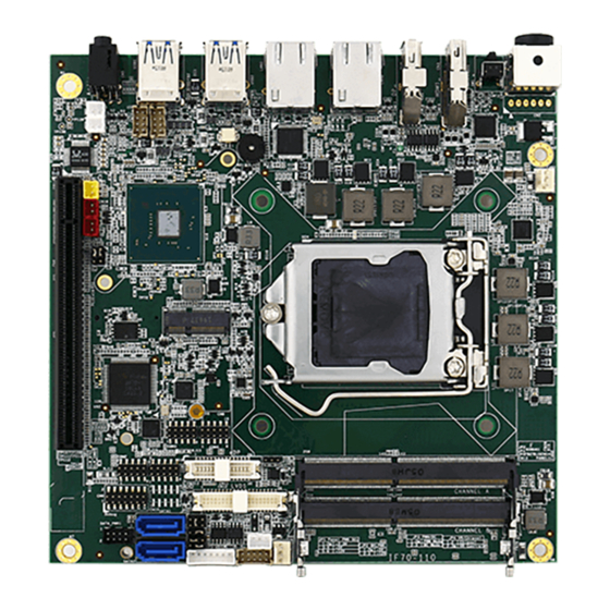
Page 12: Functional Description
IF70 Mini-ITX SBC User Manual 1.4 Functional Description Function block (V100) -
Page 13: Physical Description
0BChapter 1: General Information 1.5 Physical Description Board Dimensions (V100) -
Page 14: Chapter 2: Hardware Installation
Chapter 2: Hardware Installation This chapter provides information on how to use jumpers and connectors on the IF70 Mini-ITX SBC. Be cautious while working with these modules. Carefully read the content of this chapter in order to avoid any damages. -
Page 15: Motherboard Components
1BChapter 2: Hardware Installation 2.1 Motherboard Components 2.1.1 Component Side IF70 Mini-ITX SBC Top Layer (CPU Side, Top View) IF70 Mini-ITX SBC Side Layer (IO Side, Front View) -
Page 16: Solder Side
IF70 Mini-ITX SBC User Manual 2.1.2 Solder Side IF70 Mini-ITX SBC Bottom Layer (IO Side, Top View) -
Page 17: Memory Module (So-Dimm) Installation
1BChapter 2: Hardware Installation 2.2 Memory Module (SO-DIMM) Installation The IF70 Mini-ITX SBC has two 260-pin SODIMM slot. The socket supports DDR4. When installing the memory unit, please follow the steps below: 1. Firmly insert the SO-DIMM at an angle of about 30-degree into the slot. Align the SO-DIMM with the slot until it is fully inserted. -
Page 18: I/O Equipment Installation
2.3.3 HDMI The IF70 Mini-ITX SBC has one HDMI port that can be connected to an external LCD monitor. Use HDMI cable to connect to an external LCD monitor, and connect the power cable to the outlet. The HDMI connector is a standard 19-pin HDMI connector. -
Page 19: Jumper Settings
1BChapter 2: Hardware Installation 2.4 Jumper Settings This section explains how to set jumpers for correct configuration of the motherboard. NOTE: A pair of needle nose pliers may be helpful when working with jumpers. If you have any doubts about the best hardware configuration for your application, contact your local distributor or sales representative before you make any changes. -
Page 20: Jp1: Panel Power Select
IF70 Mini-ITX SBC User Manual 2.4.1 JP1: Panel Power Select Pin № Name 1-2 (Default) +3.3V +12V 2.4.2 JP2: Backlight Power Select Pin № Name 1-2 (Default) +12V 2.4.3 JP3: Backlight Dimming Select Pin № Name 1-2 (Default) PWM Mode DC Mode 2.4.4 JP4: Backlight Dimming Control Select... -
Page 21: Mainboard Connectors
1BChapter 2: Hardware Installation 2.5 Mainboard Connectors 2.5.1 Connector List Label Function Note Power 4P Terminal Block Din 4p dip QuickLock Connector Power 6P Wafer Wafer 6p dip HDMI Port Connector IK70 Display Interface support dual Display Port and one VGA Port application Display Port Connector Audio Jack... - Page 22 IF70 Mini-ITX SBC User Manual Label Function Note LAN1, LAN2 Gigabit Ethernet RJ45+LED Gigabit Ethernet Panel1 Front Panel Pin Header 2*5p P:2.0mm SMD 180° SATA1/ SATA2 SATA connector COM3/COM4/C Internal RS232 COM 2*5p P:2.0mm SMD 180° OM5/COM6 SATA_PWR1 SATA POWER Connector 2*5p P:2.0mm DIP 180°...
-
Page 23: Connector Description
1BChapter 2: Hardware Installation 2.5.2 Connector Description 2.5.2.1 CN1: Power 4P Terminal Block Connector The DC power input for the IF70 Mini-ITX SBC allows a voltage input of 12V DC. Pin № Signal Name Pin № Signal Name 12VDC 12VDC 2.5.2.2 CN2: Power 4P Wafer... - Page 24 Lane 3- AUX_EN_N AUX+ AUX- Hot Plug +3.3V 2.5.2.5 CN5: Audio Jack IF70 Mini-ITX SBC has two stereo audio ports with phone jack connectors, one is Line-out, and the other one is Mic-in. Color Signal Name Line-out Mic-in CN24 CN23...
- Page 25 1BChapter 2: Hardware Installation Side B Description Side A Description SMB_SHB_CLK PCIE 12V power SMB_SHB_DATA External pull down Side B Side A PCIE 12V power PCIE 12V power Side B Side A SHB_TDI PCIE 12V power SHB_TCK PCIE 12V power Side B Side A SHB_TDO...
- Page 26 IF70 Mini-ITX SBC User Manual EXP_A_RX_14_DP PCIE Group A RX8+ Side B Side A EXP_A_RX_14_DN PCIE Group A RX8- Side B Side A EXP_A_TX_13_DP PCIE Group A TX9+ Side B Side A EXP_A_TX_13_DN PCIE Group A TX9- Side B Side A...
- Page 27 1BChapter 2: Hardware Installation 2.5.2.7 CN7: NGFF M.2 KEY B Connector IF70 Mini-ITX SBC has NGFF M.2 KEY B Connector. 2.5.2.8 CN9: Digital Input / Digital Output Pin № Signal Name Pin № Signal Name DIO_5V DOUT3 DOUT1 DOUT2 DOUT0...
- Page 28 IF70 Mini-ITX SBC User Manual 2.5.2.11 CN12:LVDS Connector CN12 Pin № Signal Name Pin № Signal Name LCDVDD LVDS0_TX0_N LCDVDD LVDS0_TX0_P LCDVDD LVDS0_TX1_N LVDS0_TX1_P LVDS0_TX2_N LVDS0_TX2_P LVDS0_CLK_N LVDS0_CLK_P LVDS0_TX3_N LVDS0_TX3_P LVDS1_TX0_N LVDS1_TX0_P LVDS1_TX1_N LVDS1_TX1_P LVDS1_TX2_N LVDS1_TX2_P LVDS1_CLK_N LVDS1_CLK_P LVDS1_TX3_N LVDS1_TX3_P...
- Page 29 1BChapter 2: Hardware Installation 2.5.2.12 CN13: Backlight Connector Pin № Signal Name +BKLPWR_R +BKLPWR_R +BKLPWR_R BRIGHT BLON_5V 2.5.2.13 CN14: Backlight Brightness Control Pin № Signal Name +V5S VRD_ADC 2.5.2.14 CN15 / CN16/ CN17: Power output wafer 2.5.2.15 CN18: Power output wafer Pin №...
- Page 30 IF70 Mini-ITX SBC User Manual Pin № Signal Name Pin № Signal Name Pin № Signal Name Pin № Signal Name USB_VCC USB_VCC9 USB_VCC8 USB_VCC USB_DN USB_DN USB_DN USB_DN USB_DP USB_DP USB_DP USB_DP 2.5.2.17 CN22: ISP PORT Pin № Signal Name Pin №...
- Page 31 IF70 Mini-ITX SBC has NGFF M.2 KEY E connector. 2.2.2.22 LAN1, LAN2: LAN Conector IF70 Mini-ITX SBC has two Ethernet connectors located on the front. Ethernet ports provide a standard RJ45 10/100/1000 Mbps jack connector with LED indicators on the front side to show its Active/ Link status and Speed status.
- Page 32 IF70 Mini-ITX SBC User Manual Pin № Signal Pin № Signal Signal Pin № Signal Name Name № Name Name DCDE# DSRE# DCDF# DSRF# RXDE RTSE# RXDF RTSF# TXDE CTSE# TXDF CTSF# DTRE# RIE# DTRF# RIF# +V5S +V5S Signal Name Pin №...
- Page 33 Pin № Signal Name +V12S +V12S +V5S +V5S 2.5.2.27 FAN1 / FAN2: FAN Connector FAN1 FAN2 2.5.2.28 J3: DDR4 SO-DIMM 2.5.2.29 J2: DDR4 SO-DIMM 2.5.2.30 CN8: NGFF M.2 KEY E Connector The IF70 Mini-ITX SBC has NGFF M.2 KEY E connector.
- Page 34 IF70 Mini-ITX SBC User Manual 2.5.2.31 USB1, USB2 (USB 3.1) Connector Pin № Signal Name Pin № Signal Name USB_D- USB_D+ STDA_SSRX- STDA_SSRX+ USB1, USB2 GND_DRAIN STDA_SSTX- STDA_SSTX+...
-
Page 35: Chapter 3: Insyde H20 Bios Setup
2BChapter 3: Insyde H20 BIOS Setup Chapter 3: Insyde H20 BIOS Setup This chapter describes the different settings available in the INSYDE BIOS that comes with the board. This chapter offers information on the Award BIOS installation utility. 4.1 How and When to Use BIOS Setup 4.2 BIOS Functions 4.3 Using Recovery Wizard to Restore Computer 4.4 How to Enable Watchdog... -
Page 36: How And When To Use Bios Setup
IF70 Mini-ITX SBC User Manual 3.1 How and When to Use BIOS Setup To enter the BIOS setup, you need to connect an external USB keyboard, external monitor and press Del key when the prompt appears on the screen during start up. The prompt screen shows only few seconds so need press Del key quickly. -
Page 37: Bios Functions
2BChapter 3: Insyde H20 BIOS Setup 3.2 BIOS Functions 3.2.1 Main Menu The Main menu displays the basic information about yoursystem including BIOS version, processor RC version, system language, time, and date. When you enter BIOS setup, the first menu that appears on the screen is the main menu.It contains the system information including BIOS version, processor RC version, system language, time, and date. -
Page 38: Advanced
IF70 Mini-ITX SBC User Manual 3.2.2 Advanced Select the Advanced Tab from the setup menu to enter the advanced BIOS setup screen. You can select any of the items on the left frame of the screen to go to the sub menu for the item, such as CPU Configuration. - Page 39 2BChapter 3: Insyde H20 BIOS Setup SIO F81866A Configures SIO F81866A Enter Opens submenu parameters Console Configures Console Redirection Enter Opens submenu Redirection parameters 3.2.2.1 CPU Configuration BIOS Setting Description Setting Option Effect Intel (VMM) Enable or disable Enable/Disable When enabled, a Virtualization Intel Virtualization VMM can utilized...
- Page 40 IF70 Mini-ITX SBC User Manual 3.2.2.2 Power & Performance BIOS Setting Description Setting Option Effect CPU – Power Configure CPU – Enter Enters sub-menu Management Control Power Management Control parameters...
- Page 41 2BChapter 3: Insyde H20 BIOS Setup BIOS Setting Description Setting Option Effect Boot Configure Boot -Max non-turbo Select the performance state Performance Performance Mode performance that the BIOS will set starting Mode parameters -Max battery from reset vector -Turbo Performance Intel SpeedStep Configure Intel Enabled/ Disabled...
- Page 42 IF70 Mini-ITX SBC User Manual 3.2.2.2.1 How to Enable/Disable Turbo Mode...
- Page 43 2BChapter 3: Insyde H20 BIOS Setup 3.2.2.3 System Agent (SA) Configuration...
- Page 44 IF70 Mini-ITX SBC User Manual BIOS Setting Description Setting Option Effect Graphics Configure Graphics Enter Opens sub-menu Configuration Configuration parameters PEG Port Configure PEG Port Enter Opens sub-menu Configuration Configuration parameters Vt-d Intel® Virtualization Enabled Vt-d capability Technology for Disabled Directed I/O 3.2.2.3.1 Graphics Configuration...
- Page 45 2BChapter 3: Insyde H20 BIOS Setup BIOS Setting Description Setting Effect Option Graphics Turbo Graphics Turbo 14-31 Select Graphics Turbo IMON IMON Current IMON Current Current values supported values supported Primary Display Select Primary Auto Select which of IGFX/PEG/ Display IGFX PCI Graphics device should be primary display or select SG for...
- Page 46 IF70 Mini-ITX SBC User Manual 3.2.2.3.2 PEG Port Configuration...
- Page 47 2BChapter 3: Insyde H20 BIOS Setup BIOS Setting Description Setting Option Effect Enable Root Port Configure Root Port Enabled Enable or disable Root Port parameters Disabled Auto Max Link Speed Select Max Link Speed Auto Configure PEG 0:1:0 Max Gen1 Speed Gen2 Gen3...
- Page 48 IF70 Mini-ITX SBC User Manual -Auto Generate BDAT Generate BDAT PEG -Disabled Enable to generate BDAT PEG Margin Margin Data -Generate Port PCIe margin tables Data Gitter Data PCIe Rx CEM PCIe Rx CEM Test Disabled Enable/ Disable PEG Rx CEM...
- Page 49 2BChapter 3: Insyde H20 BIOS Setup 3.2.2.3.3 VT-d BIOS Setting Description Setting Option Effect Vt-d Intel® Virtualization Enabled Vt-d capability Technology for Disabled Directed I/O...
- Page 50 IF70 Mini-ITX SBC User Manual 3.2.2.4 PCH-IO Configuration BIOS Setting Description Setting Option Effect PCI Express Configure PCI Enter Opens sub-menu Configuration Express settings SATA And RST Configure SATA Enter Opens sub-menu Configuratuion And RST settings USB Configuration Configure USB...
- Page 51 2BChapter 3: Insyde H20 BIOS Setup 4.2.2.4.1 PCI Express Configuration BIOS Setting Description Setting Option Effect PCI Express Clock PCI Express Clock Enabled PCI Express Clock Gating Gating settings Disabled Gating Enable/ Disable for each root port PCI Port assigned PCI Port assigned Value Choose value...
- Page 52 IF70 Mini-ITX SBC User Manual...
- Page 53 2BChapter 3: Insyde H20 BIOS Setup BIOS Setting Description Setting Option Effect PCI Express Root Port 4 Control the PCI Enter Opens sub-menu Express Root Port 4 Topology Topology settings Unknown Identify the SATA Topology if it is Default or ISATA or Flex or DirectConnect or SATA Express ASPM...
- Page 54 IF70 Mini-ITX SBC User Manual 3.2.2.4.1 SATA and RST Configuration...
- Page 55 2BChapter 3: Insyde H20 BIOS Setup 3.2.2.4.2 USB Configuration BIOS Setting Description Setting Option Effect USB Port Disable USB Port Disable Disable Selectively Enable/ Override Override Select Per-Pin Disable the configuration corresponding USB port from reporting a Device Connection to the controller...
- Page 56 IF70 Mini-ITX SBC User Manual 3.2.2.4.3 State After G3 BIOS Setting Description Setting Option Effect State After G3 State After G3 S0 State Specify what state configuration S5 State to go to when power is re-applied after a power failure...
- Page 57 2BChapter 3: Insyde H20 BIOS Setup 3.2.2.5 PCH-FW Configuration BIOS Setting Description Setting Effect Option ME State ME State Disabled When Disabled ME will be put into configuration Enabled ME Temporarily Disabled Mode Manageability Manageability Disabled Enable/ Disable Intel Manageability Features State Features State Enabled...
- Page 58 IF70 Mini-ITX SBC User Manual Comms Hub Comms Hub Disabled Enable/Disable support for Comms Support Support Enabled JHI Support JHI Support Disabled Enable/Disable Intel DAL Host Enabled Interface Service (JHI) Core BIOS Core BIOS Disabled Enable /Disable Core BIOS Done...
- Page 59 2BChapter 3: Insyde H20 BIOS Setup PET Progress PET Progress Disabled Enable/ Disable PET configuration Enabled Events Progress to receive PET Events. Watchdog Watchdog Timer Disabled Enable/ Disable configuration Enabled Watchdog Timer Secure Erase Change Secure Simulated Performs SE flow without Mode Erase Mode erasing SSD...
- Page 60 IF70 Mini-ITX SBC User Manual 3.2.2.6 SIO F81866A...
- Page 61 2BChapter 3: Insyde H20 BIOS Setup BIOS Setting Description Setting Option Effect Serial Port A ~ Configure Serial port Disable No configuration Serial Port D settings Enable User configuration Auto EFI/OS chooses configuration Watchdog Timer Disable Enable or disable Watchdog configuration Enable Timer...
- Page 62 IF70 Mini-ITX SBC User Manual 3.2.2.6.2 GPIO Configuration BIOS Setting Description Setting Option Effect Internal Internal Resistance Push Pull User can pull internal Resistance configuration Open Drain resistance push-pull / open-drain Input/ Output GPIO pin Input Set GPIO pin is input or...
- Page 63 2BChapter 3: Insyde H20 BIOS Setup 3.2.2.7 Console Redirection BIOS Setting Description Setting Effect Option Console Serial Console Enabled Enable Console Redirection Redirect Redirection Disabled Function Function settings Terminal Type Console VT_100 Set Console Redirection Terminal Redirection VT_100+ Type Terminal Type VT_UTF8 settings PC_ANSI...
- Page 64 IF70 Mini-ITX SBC User Manual bit settings Stop Bits Console 1 Bit Set Console Redirection Stop Redirection Stop 2 Bits Bits Bits settings Flow Control Console None Set Console Redirection Stop Redirection Stop RTS/ CTS Flow Control Type Flow Control Type...
-
Page 65: Security
2BChapter 3: Insyde H20 BIOS Setup 3.2.3 Security BIOS Setting Description Setting Option Effect TrEE Protocol Choose TrEE TrEE Protovol Version Protocol Version Version: 1.0 or 1.1 TPM Availability TPM Availability Available When hidden don’t configuration Hidden exposes TPM to 0 TPM Operation TPM Operation Select one of the... -
Page 66: Power
IF70 Mini-ITX SBC User Manual 3.2.4 Power BIOS Setting Description Setting Option Effect ACPI S3 ACPI S3 Disabled Enable/ Disable configuration Enabled ACPI S1/S3 Sleep state Auto Wake on S5 Auto Wake on S5 Disabled Auto Wake on S5, configuration... -
Page 67: Boot
2BChapter 3: Insyde H20 BIOS Setup 3.2.5 Boot BIOS Setting Description Setting Option Effect Boot Type Boot Type UEFI Boot Type Select boot type to Dual type, configuration Legacy type or UEFI type Quick Boot Quick Boot Enabled Allows InsydeH20 to skip configuration Disabled certain tests while booting. -
Page 68: Exit
IF70 Mini-ITX SBC User Manual Boot Type Boot Type Order Enter Opens sub-menu Order 3.2.6 Exit... -
Page 69: Using Recovery Wizard To Restore Computer
2BChapter 3: Insyde H20 BIOS Setup 3.3 Using Recovery Wizard to Restore Computer Note: Before starting the recovery process, make sure to backup all user data. The data will be lost after the recovery process. Important: Before starting the recovery process, remove any expansion card. To enable quick one-key recovery procedure: 1. -
Page 70: How To Enable Watchdog
IF70 Mini-ITX SBC User Manual 3.4 How to Enable Watchdog To enable Watchdog, you need to download Winmate Watchdog utility. Find more information on Watchdog in “Watchdog Guide” that you can download from Winmate Download Center or File Share. Refer to the User Manual for more details. - Page 71 2BChapter 3: Insyde H20 BIOS Setup 3. In Watchdog utility window set countdown time and periodically feed time, or disable watchdog. Example: Every 10 min watchdog will monitor the system, in case any error occurs the system will restart automatically when the countdown time reaches 0.
-
Page 72: Chapter 4: Driver Installation
IF70 Mini-ITX SBC User Manual Chapter 4: Driver Installation This chapter contains driver installation guide. Follow the instructions below to complete the installation. You will quickly complete the installation. This chapter provides instructions on how to install drivers on the IF70 Mini-ITX SBC. -
Page 73: Chipset Driver
3BChapter 4: Driver Installation 4.1 Chipset Driver Follow instructions below to install Chipset driver. 1. Open the Driver CD (included in the package) and select Chipset driver. - Page 74 IF70 Mini-ITX SBC User Manual 2. Installation window will pop up, select Next. Select Accept to agree with the terms of license agreement.
- Page 75 3BChapter 4: Driver Installation 4. Check the ReadMe file information, select Install to continue. 5. Wait for the driver to be installed. When installation completed, select Restart Now to restart your computer.
-
Page 76: Graphic Driver
IF70 Mini-ITX SBC User Manual 4.2 Graphic Driver Follow instructions below to install Graphic driver. 1. Open the Driver CD (included in the package) and select Graphic driver. 2. Installation window will pop up, select Next. - Page 77 3BChapter 4: Driver Installation 3. Select Accept to agree with the terms of license agreement.
- Page 78 IF70 Mini-ITX SBC User Manual 4. Check the ReadMe file information, select Next to continue. 5. Wait for the driver to be installed.
- Page 79 3BChapter 4: Driver Installation 6. Select Next to continue.
- Page 80 IF70 Mini-ITX SBC User Manual 7. After installation is completed, select “Yes, I want to restart this computer now”, and click Finish.
-
Page 81: Management Engine (Me)
3BChapter 4: Driver Installation 4.3 Management Engine (ME) Follow instructions below to install Management Engine (ME) . 1. Open the Driver CD (included in the package) and select ME driver. 2. Select Next to start the installation. - Page 82 IF70 Mini-ITX SBC User Manual 3. Select Next to agree with the terms of license agreement. 4. Wait for the driver to be installed. When installation completed, select Finish complete...
-
Page 83: Audio Driver
3BChapter 4: Driver Installation installation. 4.4 Audio Driver Follow instructions below to install Audio driver. 1. Open the Driver CD (included in the package) and select Audio driver. 2. Select Next to continue. -
Page 84: Ethernet Driver
IF70 Mini-ITX SBC User Manual 3. When installation completed, select Finish complete installation. 4.5 Ethernet Driver Follow instructions below to install LAN driver. 1. Open the Driver CD (included in the package) and select LAN driver. 2. When compression is complete, select Next. - Page 85 3BChapter 4: Driver Installation 3. Read the license agreement, and then select Next. 4. System displays the installed packages, select Next.
- Page 86 IF70 Mini-ITX SBC User Manual 5. Confirm the installation, select Install to start the installation. 6. When installation is completed, select Finish to close the window.
-
Page 87: Watchdog Driver Installation
3BChapter 4: Driver Installation 4.6 Watchdog Driver Installation For more details about Winmate Watchdog, please download Watchdog Guide from Winmate Downloads Center here. Follow instructions below to install Watchdog driver. 1. Type “cmd” in the run box then the cmd.exe will appear in programs. - Page 88 IF70 Mini-ITX SBC User Manual install 4. When Windows Security dialog appear, select to continue the Installation.
- Page 89 3BChapter 4: Driver Installation 5. Wait for installation to complete. When installation is complete, press any key to close. 6. Open the Driver CD (included in the package) and select Watchdog AP. 7. Select Next.
- Page 90 IF70 Mini-ITX SBC User Manual 8. The installed storage location is displayed, select Next to continue. 9. Select Next to start the installation. 10. When installation is completed, select Finish to close the window.
-
Page 91: Digital Io Driver Installation
IF70 Mini-ITX SBC User Manual 4.7 Digital IO Driver Installation For more details about Winmate Watchdog, please download Digital IO Guide from Winmate Downloads Center: Follow instructions below to install Digital IO river. 1. Type “cmd” in the run box then the cmd.exe will appear in programs. - Page 92 IF70 Mini-ITX SBC User Manual 6. Open the Driver CD (included in the package) and select Digital IO AP.
- Page 93 3BChapter 4: Driver Installation...
-
Page 94: Chapter 5: Technical Support
IF70 Mini-ITX SBC User Manual Chapter 5: Technical Support This chapter includes the directory for technical support. Free technical support is available from our engineers every business day. We are always ready to give advice on application requirements or specific information on the installation and operation of any of our products. -
Page 95: Drivers
4BChapter 5: Technical Support 5.1 Drivers The list of drivers available for IF70 Mini-ITX SBC: Item Driver Chipset Driver Graphic Driver ME Driver Audio Driver Ethernet Driver Watchdog Driver/AP Digital IO Driver/AP To find the Drivers, please refer to the Driver CD that comes in the package or contact us. - Page 96 Winmate Inc. 9F, No.111-6, Shing-De Rd., San-Chung District, New Taipei City 24158, Taiwan, R.O.C www.winmate.com Copyright © Winmate Inc. All rights reserved.
Need help?
Do you have a question about the IF70 Mini-ITX SBC and is the answer not in the manual?
Questions and answers