
Related Manuals for Winmate IT70


Summary of Contents for Winmate IT70
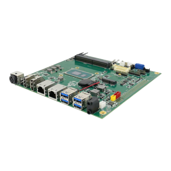
- Page 1 IT70 Motherboard Mini-ITX SBC with Intel® 11th Gen Core i5 processor, HDMI, Display Port, LVDS, Dual Giga Ethernet, USB 3.2 Gen 2 x1, and NGFF Interface User Manual Document Version 1.2 Document Part No. 9171111I104M...
-
Page 3: Table Of Contents
IT70 Motherboard User Manual Contents Preface ............................3 About This User Manual ........................ 5 Chapter 1: General Information ....................6 1.1 Introduction ..........................6 1.2 Features ..........................6 1.3 Motherboard Specifications ....................7 1.4 Functional Description ......................9 1.5 Physical Description ........................ 9 Chapter 2: Hardware Installation .................... - Page 4 IT70 Motherboard User Manual 3.3 Using Recovery Wizard to Restore Computer ............... 49 3.4 How to Enable Watchdog ...................... 50 Chapter 4: Driver Installation ...................... 51 4.1 Chipset Driver ........................51 4.2 Graphic Driver ........................53 4.3 Management Engine (ME) ....................55 4.4 Audio Driver ..........................
-
Page 5: Preface
Preface Preface Copyright Notice No part of this document may be reproduced, copied, translated, or transmitted in any form or by any means, electronic or mechanical, for any purpose, without the prior written permission of the original manufacturer. Trademark Acknowledgement Brand and product names are trademarks or registered trademarks of their respective owners. - Page 6 IT70 Motherboard User Manual Packing List Before using this Motherboard, please make sure that all the items listed below are present in your package: • IT70 Motherboard • User Manual & Driver CD If any of these items are missing or damaged, contact your distributor or sales representative immediately.
-
Page 7: About This User Manual
This User Manual provides information about using the IT70 Motherboard. The documentation set for the IT70 Motherboard provides information for specific user needs, and includes: • IT70 Motherboard User Manual – contains detailed description on how to use the motherboard, its components and features. -
Page 8: Chapter 1: General Information
Chapter 1: General Information 1.1 Introduction Thank you for choosing the IT70 Motherboard. The IT70 Motherboard is powered by Intel® 11th Generation Core™ processor based on 64-bit, multi-core processors built on 10-nanometer process technology. The processors delivers the performance and high scalability cutting-edge embedded computing application. -
Page 9: Motherboard Specifications
Chapter 1: General Information 1.3 Motherboard Specifications Model Name IT70 Mini-ITX SBC Intel® Core™ i5-1135G7 (8M Cache, up to 4.20 GHz, no vPro) Intel® Core™ i5-1145G7 (8M Cache, up to 4.40 GHz, With vPro) System Memory 2 x DDR4 3200 SO-DIMM, up to 64 GB 1 x M.2 M-Key Slot for M.2 2242 SATA SSD or M.2 2280... - Page 10 IT70-100 Mini-ITX SBC Packing List Standard IT70 Mini-ITX SBC Manual & Driver CD NOTE: 1. Accessories and Integrated Options may vary depending on your configuration. The product shown in this document is a standard model. For diagrams that contain customized or optional I/O, please contact the Winmate Sales Team for more information.
-
Page 11: Functional Description
Chapter 1: General Information 1.4 Functional Description Function block (V100) 1.5 Physical Description Board Dimensions... -
Page 12: Chapter 2: Hardware Installation
IT70 Motherboard User Manual Chapter 2: Hardware Installation This chapter provides information on how to use jumpers and connectors on the IT70 Motherboard. Be cautious while working with these modules. Carefully read the content of this chapter in order to avoid any damages. -
Page 13: Solder Side
2.1.3 Solder Side 2.2 Memory Module (SO-DIMM) Installation The IT70 SBC Motherboard has two 260-pin SODIMM slot. The socket supports DDR4. When installing the memory unit, please follow the steps below: 1. Firmly insert the SO-DIMM at an angle of about 30-degree into the slot. Align the SO-DIMM with the slot until it is fully inserted. -
Page 14: I/O Equipment Installation
IT70 Motherboard User Manual 2.3 I/O Equipment Installation 2.3.1 12V DC in The IT70 Motherboard allows plugging 12V DC-IN jack on the board without another power module converter under power consumption by Intel® 11th Generation Core i7/i5/i3 Processor. 2.3.2 Serial COM Port Two COM Port Pin Headers build in the motherboard. -
Page 15: Jumper Settings
Chapter 2: Hardware Installation 2.4 Jumper Settings This section explains how to set jumpers for correct configuration of the motherboard. NOTE: A pair of needle nose pliers may be helpful when working with jumpers. If you have any doubts about the best hardware configuration for your application, contact your local distributor or sales representative before you make any changes. -
Page 16: Jp2: Backlight Power Select
IT70 Motherboard User Manual 2.4.2 JP2: Backlight Power Select Pin № Signal Name 1-2 (Default) +12V 2.4.3 JP3: Backlight Dimming Select Pin № Signal Name 1-2 (Default) PWM Mode DC Mode 2.4.4 JP4: Backlight Dimming Control Select Pin № Signal Name... -
Page 17: Mainboard Connectors
Chapter 2: Hardware Installation 2.5 Mainboard Connectors 2.5.1 Connectors List Connectors Label Function Note Power Din 4P Connector Din 4p dip Quick Lock Power 6P Wafer Wafer 6p dip CN3/ HDMI1 (Optional) HDMI Port Connector HDMI1.4a CN4/ DP Display Port Connector Display Port 1.2 Audio Jack PJD-035-17A... -
Page 18: Connector Description
Lane 3+ Lane 3- AUX_EN_N AUX+ AUX- Hot Plug +3.3V 2.5.2.5 CN5: Audio Jack IT70 Mini-ITX SBC has two stereo audio ports with phone jack connectors, one is Line-out, and the other one is Mic-in. Color Signal Name Line-out Mic-in... - Page 19 Chapter 2: Hardware Installation 2.5.2.6 CN6: SHB Express PCIEx16 No Side B Description Side A Description External pull Side B SMB_SHB_CLK PCIE 12V power Side A SMB_SHB_DATA down Side B PCIE 12V power Side A PCIE 12V power Side B SHB_TDI PCIE 12V power Side A...
- Page 20 IT70 Motherboard User Manual No Side B Description Side A Description Side B CLK_PCIE_SHB_B2_N NC Side A Side B Side A CLK_PCIE_SHB_B3_P Side B Side A CLK_PCIE_SHB_B3_N NC Side B CLK_PCIE_SHB_A0_P Side A Side B CLK_PCIE_SHB_A0_N NC Side A Side B...
- Page 21 Chapter 2: Hardware Installation 2.5.2.7 CN8: NGFF M.2 KEY E Connector The IT70 Mini-ITX SBC NGFF M.2 connecter supports 2 M.2 card applications: • PCIe I/F + USB 2.5.2.8 CN9: Digital Input / Digital Output Pin № Pin № Signal Name...
- Page 22 IT70 Motherboard User Manual 2.5.2.10 CN12: LVDS Connector Pin № Pin № Signal Name Signal Name LCDVDD LVDS0_TX0_N LCDVDD LVDS0_TX0_P LCDVDD LVDS0_TX1_N LVDS0_TX1_P LVDS0_TX2_N LVDS0_TX2_P LVDS0_CLK_N LVDS0_CLK_P LVDS0_TX3_N LVDS0_TX3_P LVDS1_TX0_N LVDS1_TX0_P LVDS1_TX1_N LVDS1_TX1_P LVDS1_TX2_N LVDS1_TX2_P LVDS1_CLK_N LVDS1_CLK_P LVDS1_TX3_N LVDS1_TX3_P 2.5.2.11 CN13: Backlight Connector Pin №...
- Page 23 2.5.1.13 CN24: Speaker Right 2.2.2.16 LAN1, LAN2: LAN Connector IT70 Mini-ITX SBC has two Ethernet connectors located on the front. Ethernet ports provide a standard RJ45 10/100/1000 Mbps jack connector with LED indicators on the front side to show its Active/ Link status and Speed status.
- Page 24 IT70 Motherboard User Manual 2.5.2.17 Panel1: Front Panel Pin Header Pin № Pin № Signal Name Signal Name PW_LED+ HD_LED+ HD_LED- PW_BT BRI+ RST-BT BRI- 5VSB 2.5.2.18 SATA1: SATA connector Pin № Pin № Signal Name Signal Name SATA_TXP SATA_TXN...
- Page 25 Chapter 2: Hardware Installation 2.5.2.20 SATA_PWR1: SATA POWER Connector Pin № Pin № Signal Name Signal Name +V12S +V12S +V5S +V5S 2.5.2.21 FAN1/ FAN2: FAN Connector Pin 1 GND Pin 1 GND Pin 2 +12 V Pin 2 +12 V Pin 3 SENSE Pin 3 SENSE FAN1...
-
Page 26: Chapter 3: Insyde H20 Bios Setup
IT70 Motherboard User Manual Chapter 3: INSYDE H20 BIOS Setup This chapter provides information on how to use BIOS setup, its functions and menu. 3.1 How and When to Use BIOS Setup To enter the BIOS setup, you need to connect an external USB keyboard, external monitor and press Del key when the prompt appears on the screen during start up. -
Page 27: Bios Functions
IT70 SBC User Manual 3.2 BIOS Functions 3.2.1 Main Menu The Main menu displays the basic information about your system including BIOS version, processor RC version, system language, time, and date. When you enter BIOS setup, the first menu that appears on the screen is the main menu. It contains the system information including BIOS version, processor RC version, system language, time, and date. -
Page 28: Advanced
IT70 Motherboard User Manual 3.2.2 Advanced Select the Advanced Tab from the setup menu to enter the advanced BIOS setup screen. You can select any of the items on the left frame of the screen to go to the sub menu for the item, such as CPU Configuration. - Page 29 IT70 SBC User Manual 3.2.2.1 CPU Configuration BIOS Setting Description Setting Option Effect Intel (VMM) Enable or disable Enable/Disable When enabled, a VMM can Virtualization Intel Virtualization utilized the additional hardware Technology Technology. capabilities provided by Vanderpool Technology. Active Processor...
- Page 30 IT70 Motherboard User Manual 3.2.2.2 Power & Performance BIOS Setting Description Setting Option Effect CPU – Power Configure CPU – Enter Enters sub-menu Management Control Power Management Control parameters...
- Page 31 IT70 SBC User Manual BIOS Setting Description Setting Option Effect Boot Performance Configure Boot - Max non-turbo Select the performance state Mode Performance Mode performance that the BIOS will set starting parameters - Max battery from reset vector - Turbo Performance...
- Page 32 IT70 Motherboard User Manual 3.2.2.2.1 How to Enable/Disable Turbo Mode...
- Page 33 IT70 SBC User Manual 3.2.2.3 System Agent (SA) Configuration BIOS Setting Description Setting Option Effect Graphics Configure Graphics Enter Opens sub-menu Configuration Configuration parameters PEG Port Configure PEG Port Enter Opens sub-menu Configuration Configuration parameters Vt-d Intel® Virtualization Enabled Vt-d capability...
- Page 34 IT70 Motherboard User Manual 3.2.2.3.1 Graphics Configuration BIOS Setting Description Setting Option Effect Graphics Turbo Graphics Turbo 14-31 Select Graphics Turbo IMON IMON Current IMON Current Current values supported values supported Primary Display Select Primary Auto Select which of IGFX/PEG/ PCI...
- Page 35 IT70 SBC User Manual 3.2.2.3.2 PEG Port Configuration BIOS Setting Description Setting Option Effect Enable Root Port Configure Root Enabled Enable or disable Root Port Port parameters Disabled Auto Max Link Speed Select Max Link Auto Configure PEG 0:1:0 Max...
- Page 36 IT70 Motherboard User Manual 0.01x 0.001x Program PCIe Program PCIe Disabled PCIe ASPM will be ASPM after ASPM after programmed before OpROM OpROM OpROM Enabled PCIe ASPM will be programmed after OpROM Program Static Program Static Disabled Program Phase1 Presents/...
- Page 37 IT70 SBC User Manual 3.2.2.3.3 VT-d BIOS Setting Description Setting Option Effect Vt-d Intel® Virtualization Enabled Vt-d capability Technology for Directed I/O Disabled 3.2.2.4 PCH-IO Configuration BIOS Setting Description Setting Option Effect PCI Express Configure PCI Express Enter Opens sub-menu...
- Page 38 IT70 Motherboard User Manual 3.2.2.4.1 PCI Express Configuration BIOS Setting Description Setting Option Effect PCI Express Clock PCI Express Clock Enabled PCI Express Clock Gating Gating Gating settings Disabled Enable/ Disable for each root port PCI Port assigned PCI Port assigned to...
- Page 39 IT70 SBC User Manual BIOS Setting Description Setting Option Effect PCI Express Control the PCI Enter Opens sub-menu Root Port 7 Express Root Port 7 Topology Topology settings Unknown Identify the SATA Topology if it is Default or ISATA or...
- Page 40 IT70 Motherboard User Manual 3.2.2.4.2 SATA and RST Configuration 3.2.2.4.3 USB Configuration BIOS Setting Description Setting Option Effect USB Port Disable USB Port Disable Disable Selectively Enable/ Disable Override Override Select Per-Pin the corresponding USB port configuration from reporting a Device...
- Page 41 IT70 SBC User Manual 3.2.2.4.4 State After G3 BIOS Setting Description Setting Option Effect State After G3 State After G3 S0 State Specify what state to go to configuration S5 State when power is re-applied after a power failure (G3 state)
- Page 42 IT70 Motherboard User Manual BIOS Setting Description Setting Option Effect ME State ME State Disabled When Disabled ME will be put configuration Enabled into ME Temporarily Disabled Mode Manageability Manageability Disabled Enable/ Disable Intel Features State Features State Enabled Manageability Features...
- Page 43 IT70 SBC User Manual 3.2.2.6 Super IO BIOS Setting Description Setting Option Effect Serial Port A ~ Configure Serial port Disable No configuration Serial Port D settings Enable User configuration Auto EFI/OS chooses configuration Watchdog Timer Disable Enable or disable...
- Page 44 IT70 Motherboard User Manual 3.2.2.6.1 Hardware Monitor BIOS Setting Description Setting Option Effect FAN1 Mode FAN1 Mode Manual Linear Select FAN1 Mode configuration Stage configuration 3.2.2.6.2 GPIO Configuration BIOS Setting Description Setting Option Effect Internal Resistance Internal resistance Push Pull...
-
Page 45: Security
IT70 SBC User Manual 3.2.3 Security BIOS Setting Description Setting Option Effect TrEE Protocol Choose TrEE TrEE Protocol Version: Version Protocol Version 1.0 or 1.1 When hidden don’t TPM Availability TPM Availability Available configuration Hidden exposes TPM to 0 TPM Operation... -
Page 46: Power
IT70 Motherboard User Manual 3.2.4 Power BIOS Setting Description Setting Option Effect ACPI S3 ACPI S3 Disabled Enable/ Disable ACPI configuration Enabled S1/S3 Sleep state Auto Wake on S5 Auto Wake on S5 Disabled Auto Wake on S5, by Day... -
Page 47: Boot
IT70 SBC User Manual 3.2.5 Boot BIOS Setting Description Setting Option Effect Boot Type Boot Type UEFI Boot Type Select boot type to Dual type, configuration Legacy type or UEFI type Quick Boot Quick Boot Enabled Allows InsydeH20 to skip certain... - Page 48 IT70 Motherboard User Manual...
- Page 49 IT70 SBC User Manual...
-
Page 50: Exit
IT70 Motherboard User Manual 3.2.6 Exit... -
Page 51: Using Recovery Wizard To Restore Computer
IT70 SBC User Manual 3.3 Using Recovery Wizard to Restore Computer Note: Before starting the recovery process, make sure to backup all user data. The data will be lost after the recovery process. Important: Before starting the recovery process, remove any expansion card. -
Page 52: How To Enable Watchdog
IT70 Motherboard User Manual 3.4 How to Enable Watchdog To enable Watchdog, you need to download Winmate Watchdog utility. Find more information on Watchdog in “Watchdog Guide” that you can download from Winmate Download Center or File Share. To enable watchdog in Watchdog AP follow the instructions below: 1. -
Page 53: Chapter 4: Driver Installation
This chapter contains driver installation guide. Follow the instructions below to complete the installation. You will quickly complete the installation. This chapter provides instructions on how to install drivers on the IT70 Motherboard. 4.1 Chipset Driver Follow instructions below to install Chipset driver. - Page 54 Chapter 4: Driver Installation 3. Select Accept to agree with the terms of license agreement. 4. Check the ReadMe file information, select Install to continue. Wait for the driver to be installed. When installation completed, click Finish.
-
Page 55: Graphic Driver
IT70 SBC User Manual 4.2 Graphic Driver Follow instructions below to install Graphic driver. 1. Open the Driver CD (included in the package) and select Installer driver. 2. Installation window will pop up, click Begin installation. - Page 56 Chapter 4: Driver Installation 3. Check the I agree to the Intel Terms and Conditions, then click Next >. 4. After installation is completed, click Finish.
-
Page 57: Management Engine (Me)
IT70 SBC User Manual 4.3 Management Engine (ME) Follow instructions below to install Management Engine (ME) . 1. Open the Driver CD (included in the package) and select MEISetup driver. 2. Select Next to start the installation. - Page 58 Chapter 4: Driver Installation 3. Select Next to agree with the terms of license agreement. 4. When installation completed, select Finish complete installation.
-
Page 59: Audio Driver
IT70 SBC User Manual 4.4 Audio Driver Follow instructions below to install Audio driver. 1. Open the Driver CD (included in the package) and select Setup driver. 2. Select Next to continue. - Page 60 Chapter 4: Driver Installation 3. When installation completed, select Yes, I want to restart my computer now. Then click Finish.
-
Page 61: Ethernet Driver
IT70 SBC User Manual 4.5 Ethernet Driver Follow instructions below to install LAN driver. 1. Open the Driver CD (included in the package) and select LAN driver. 2. When compression is complete, select Next. - Page 62 Chapter 4: Driver Installation 3. Read the license agreement, and then select Next. 4. System displays the installed packages, select Next. 5. Confirm the installation, select Install to start the installation.
-
Page 63: Dtt Driver
IT70 SBC User Manual 6. When installation is completed, select Finish to close the window. 4.6 DTT Driver Follow instructions below to install DTT driver. 1. Open the Driver CD (included in the package) and select DTT driver. - Page 64 Chapter 4: Driver Installation 2. When compression is complete, select Next. 3. Read the license agreement, and then select Yes. 4. System displays the installed packages, select Next.
-
Page 65: Gna Driver
IT70 SBC User Manual 5. When installation is completed, select Finish to close the window. 4.7 GNA Driver Follow instructions below to install GNA driver. 1. Open the Driver CD (included in the package) and select GNA driver. 2. Right click, select Install. -
Page 66: Serial Io Driver
Chapter 4: Driver Installation 4.8 Serial IO Driver Follow instructions below to install SIO driver. 1. Open the Driver CD (included in the package) and select SetupSerialIO driver. 2. Select Next to start the installation. 3. Select Next to agree with the terms of license agreement. - Page 67 IT70 SBC User Manual 4. Click Next. 5. When installation completed, select Yes, I want to restart my computer now. Then click Finish.
-
Page 68: Resistive Touch Driver For Windows 11 System
Chapter 4: Driver Installation 4.9 Resistive Touch Driver for Windows 11 System Follow the instructions below to install the touch driver. 1. Click setup 2. Click Next to continue... - Page 69 IT70 SBC User Manual...
- Page 70 Chapter 4: Driver Installation 3. Click Yes to add this controller. 4. Restart the computer now and finish the setup.
-
Page 71: Chapter 5: Technical Support
We are always ready to give advice on application requirements or specific information on the installation and operation of any of our products. If any problem occurs immediately contact us. 5.1 Drivers The list of drivers available for IT70 Motherboard: Item Driver Audio Driver... - Page 72 NOTE...
- Page 73 Winmate Inc. 9F, No.111-6, Shing-De Rd., San-Chung District, New Taipei City 24158, Taiwan, R.O.C www.winmate.com Copyright © 2022 Winmate Inc. All rights reserved.
Need help?
Do you have a question about the IT70 and is the answer not in the manual?
Questions and answers