
Related Manuals for Winmate IT32


Summary of Contents for Winmate IT32
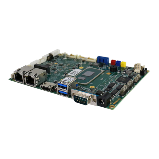
- Page 1 IT32 Motherboard 3.5” SBC with Intel® 11th Generation Core i5 Processor, HDMI, LVDS, Dual 2.5Giga Ethernet, and M.2 NGFF Interface User Manual Document Version 1.1 Document Part No. 9152111I1157...
-
Page 3: Table Of Contents
Contents Contents Preface ............................3 About This User Manual ........................ 5 Chapter 1: General Information ....................6 1.1 Introduction ..........................7 1.2 Features ..........................7 1.3 Motherboard Specifications ....................8 1.4 Functional Description ......................10 1.5 Physical Description ......................11 Chapter 2: Hardware Installation .................... - Page 4 IT32 SBC User Manual 3.9 Resistive Touch Driver for Windows 11 System ..............46 3.10 Thermal Control AP ......................50 Chapter 4: INSYDE H20 BIOS Setup ................... 57 4.1 How and When to Use BIOS Setup ..................58 4.2 BIOS Functions ........................59 4.2.1 Main Menu........................
-
Page 5: Preface
Preface Preface Copyright Notice No part of this document may be reproduced, copied, translated, or transmitted in any form or by any means, electronic or mechanical, for any purpose, without the prior written permission of the original manufacturer. Trademark Acknowledgement Brand and product names are trademarks or registered trademarks of their respective owners. - Page 6 IT32 SBC User Manual Packing List Before using this Motherboard, please make sure that all the items listed below are present in your package: IT32 Motherboard • • User Manual If any of these items are missing or damaged, contact your distributor or sales representative immediately.
-
Page 7: About This User Manual
This User Manual provides information about using the IT32 Motherboard. The documentation set for the IT32 Motherboard provides information for specific user needs, and includes: • IT32 Motherboard User Manual – contains detailed description on how to use the motherboard, its components and features. -
Page 8: Chapter 1: General Information
Chapter 1: General Information Chapter 1: General Information This chapter includes the IT32 Motherboard background information. Introduction Features Motherboard Specifications Functional Description Physical Description... -
Page 9: Introduction
Generation Core™ based on 64-bit, multi-core processor and built on 10-nanometer processor technology. In peripheral connectivity, IT32 Motherboard features one M.2 Key-E with PCIe x1, USB 2.0 for wireless, one M.2 Key-M, 2242/2280 with SATAIII or PCIe SSD, one Serial ATA III (6Gb/s) connectors, one RS232/422/485 (Default RS232) DB9 connector, three serial ports (internal connectors), 2 super-speed USB 3.2 Gen2x1 (10Gbps) connectors and four hi-speed USB 2.0... -
Page 10: Motherboard Specifications
Chapter 1: General Information 1.3 Motherboard Specifications Model Name IT32 Intel Core i5-1135G7 2.4GHz (up to 4.2GHz) Chipset Intel® SoC Integrated System 1 x Non ECC SO-DIMM, DDR4 3200 MHz, Max. 32GB Memory 1 x M.2 M-Key 2242 SATA SSD, Max. 512GB or Storage 1 x M.2 M-Key 2280 NVMe SSD, Max. - Page 11 IT32 SBC User Manual Model Name IT32 x4 SSD Security TPM 2.0 Mechanical Dimensions 146 (W)x 102(L) mm Specifications Operating 0°C ~ 60°C Temp. Environment Storage -40°C ~ 70°C Considerations Temp. Operating 10% ~ 95%, non-condensing Humidity Power Input +12V Power Input...
-
Page 12: Functional Description
Chapter 1: General Information 1.4 Functional Description Function block... -
Page 13: Physical Description
IT32 SBC User Manual 1.5 Physical Description Board Dimensions... -
Page 14: Chapter 2: Hardware Installation
Chapter 2: Hardware Installation Chapter 2: Hardware Installation This chapter provides information on how to use jumpers and connectors on the IT32 motherboard. Motherboard Components Memory Module Installation I/O Equipment Installation Jumper Settings Motherboard Connectors... -
Page 15: Motherboard Components
IT32 SBC User Manual This chapter provides information on how to use jumpers and connectors on the IT32 Motherboard. Be cautious while working with these modules. Carefully read the content of this chapter in order to avoid any damages. 2.1 Motherboard Components... -
Page 16: I/O Side
Chapter 2: Hardware Installation 2.1.2 I/O Side 2.1.3 Solder Side... -
Page 17: Memory Module (So-Dimm) Installation
IT32 SBC User Manual 2.2 Memory Module (SO-DIMM) Installation The IT32 SBC Motherboard has one 262-pin SODIMM slot. The socket supports DDR4. When installing the memory unit, please follow the steps below: 1. Firmly insert the SO-DIMM at an angle of about 30-degree into the slot. Align the SO-DIMM with the slot until it is fully inserted. -
Page 18: I/O Equipment Installation
Chapter 2: Hardware Installation 2.3 I/O Equipment Installation 2.3.1 12V DC in The IT32 Motherboard allows plugging 12V DC-IN jack on the board without another power module converter under power consumption by Intel® 11th Generation Core i5 Processor. 2.3.2 Serial COM Port One RS-232 connectors build-in the rear I/O can optional supports RS-422/ 485. -
Page 19: Jumper Settings
IT32 SBC User Manual 2.4 Jumper Settings This section explains how to set jumpers for correct configuration of the motherboard. NOTE: A pair of needle nose pliers may be helpful when working with jumpers. If you have any doubts about the best hardware configuration for your application, contact your local distributor or sales representative before you make any changes. -
Page 20: Jp3: Vr/Chipset Control Selector
Chapter 2: Hardware Installation 2.4.2 JP3: VR/Chipset Control Selector Pin № Signal Name Chipset 2-3(Default) VR Control 2.4.3 JP4: Backlight Power Selector Pin № Signal Name 1-2 (Default) +12V 2.4.4 JP5: PWM/DC Mode Control Selector Pin № Signal Name 1-2 (Default) PWM Mode DC Mode... -
Page 21: Mainboard Connectors
RJ45+LED Clear CMOS, Reset Button 2.5.1.1 DCJACK1: Power 2.5 DC Jack Connector φ The DC power input for the IT32 Motherboard allows a voltage input of 12V DC. Pin № Signal Name Pin № Signal Name 12VDC 2.5.1.2 COM1: D-Sub9 (Male) Pin №... - Page 22 DDC_CLOCK DDC_DATA 2.5.1.5 LAN1, LAN2: 2.5Gigabit Ethernet IT32 has two Ethernet connectors located on the front. Ethernet ports provide a standard RJ45 jack connector with LED indicators on the front side to show its Active/ Link status and Speed status.
-
Page 23: Internal I/O Side Connectors
IT32 SBC User Manual 2.5.2 Internal I/O Side Connectors Label Function Note Connectors Backlight Connector 7p P:2.0mm DIP 180° Backlight Brightness Control 3p P:2.0mm DIP 180° Power 6P Wafer Wafer 6p DIP USB2 USB2.0 Wafer 2*4p P:2.0mm DIP 180° USB3 USB2.0 Wafer... - Page 24 Chapter 2: Hardware Installation 2.5.2.1 CN2: Backlight Connector Pin № Signal Name Pin № Signal Name +BKLPWR_R +BKLPWR_R +BKLPWR_R BRIGHT BLON_5V Note: Please refer to JP1 settings to select Power Rating. 2.5.2.2 CN3: Backlight Brightness Control VR Knob Pin № Signal Name Pin №...
- Page 25 IT32 SBC User Manual 2.5.2.5 BT1: RTC Battery Connector Pin № Signal Name Pin № Signal Name +3.3V 2.5.2.6 SPK_L, SPK_R: Speaker Out Pin № Signal Name Pin № Signal Name LOUT+ LOUT- 2.5.2.7 AUDIO1: Audio Pin № Signal Name Pin №...
- Page 26 Chapter 2: Hardware Installation 2.5.2.8 EDP1: eDP Connector Pin № Signal Name Pin № Signal Name EMB_AUXN EMB_AUXP DP_TXN3_C +VCC_EDP_BKLT DP_TXP3_C +VCC_EDP_BKLT EPD_HPD DP_TXN2_C DP_TXP2_C DP_TXN1_C DP_TXP1_C LCDVDD LCDVDD DP_TXN0_C LCDVDD DP_TXP0_C LCDVDD +VCC_EDP_BKLT 2.5.2.9 LVDS1: LVDS Connector Pin № Signal Name Pin №...
- Page 27 IT32 SBC User Manual 2.5.2.10 SATA1: SATA Connector Pin № Signal Name Pin № Signal Name SATA_TXP SATA_TXN SATA_RXN SATA_RXP 2.5.2.11 SATA_PWR1: SATA Power Connector Pin № Signal Name Pin № Signal Name +12V +12V 2.5.2.12 5V1: 5V Power Output Pin №...
- Page 28 Chapter 2: Hardware Installation 2.5.2.15 PANEL1: Front Panel Pin Header Pin № Signal Name Pin № Signal Name +3.3V SATA_LED# PWRBTN# Backlight_ADJ+ FP_RST_N Backlight_ADJ- 2.5.2.16 CPU_FAN1: Fan Connector Pin № Signal Name Pin № Signal Name +12V SENSE 2.5.2.17 DIDO1: Digital Input / Digital Output Pin №...
- Page 29 IT32 SBC User Manual 2.5.2.19 NGFF_KEY_E1: NGFF M.2 KEY E Connector IT32 NGFF M.2 connector supports M.2 card applications: 1. PCIe I/F + USB 2.5.2.20 NGFF_KEY_M1: NGFF M.2 KEY M Connector IT32 NGFF M.2 connector supports M.2 card applications: 1. PCIe I/F + USB...
-
Page 30: Chapter 3: Driver Installation
Chapter 3: Driver Installation Chapter 3: Driver Installation This chapter contains driver installation instructions for IT32 motherboard Chipset Driver Installation Graphic Driver Installation Management Engine (ME) Audio Driver Installation Ethernet Driver Installation DTT Installation GNA Installation Serial IO Driver Resistive Touch Driver for Windows 11 System... -
Page 31: Chipset Driver
This chapter contains driver installation guide. Follow the instructions below to complete the installation. You will quickly complete the installation. This chapter provides instructions on how to install drivers on the IT32 Motherboard. 3.1 Chipset Driver Follow instructions below to install Chipset driver. - Page 32 Chapter 3: Driver Installation 3. Select Accept to agree with the terms of license agreement. 4. Check the ReadMe file information, select Install to continue.
- Page 33 IT32 SBC User Manual 5. Wait for the driver to be installed. When installation completed, select Restart Now to restart your computer.
-
Page 34: Graphic Driver
Chapter 3: Driver Installation 3.2 Graphic Driver Follow instructions below to install Graphic driver. 1. Open the Driver CD (included in the package) and select Installer driver. 2. Installation window will pop up, click Begin installation... - Page 35 IT32 SBC User Manual 3. Check the I agree to the Intel Terms and Conditions, then click Next >. 4. After installation is completed, click Finish.
-
Page 36: Management Engine (Me)
Chapter 3: Driver Installation 3.3 Management Engine (ME) Follow instructions below to install Management Engine (ME) . 1. Open the Driver CD (included in the package) and select MEISetup driver. 2. Select Next to start the installation. - Page 37 IT32 SBC User Manual 3. Select Next to agree with the terms of license agreement. 4. When installation completed, select Finish complete installation.
-
Page 38: Audio Driver
Chapter 3: Driver Installation 3.4 Audio Driver Follow instructions below to install Audio driver. 1. Open the Driver CD (included in the package) and select Setup driver. 2. Select Next to continue. - Page 39 IT32 SBC User Manual 3. When installation completed, select Yes, I want to restart my computer now. Then click Finish.
-
Page 40: Ethernet Driver
Chapter 3: Driver Installation 3.5 Ethernet Driver Follow instructions below to install LAN driver. 1. Open the Driver CD (included in the package) and select LAN driver. 2. When compression is complete, select Install Drivers. - Page 41 IT32 SBC User Manual 3. Select OK. 4. Select Close to close the window.
-
Page 42: Dtt Driver
Chapter 3: Driver Installation 3.6 DTT Driver Follow instructions below to install DTT driver. 1. Open the Driver CD (included in the package) and select DTT driver. 2. When compression is complete, select Next. - Page 43 IT32 SBC User Manual 3. Read the license agreement, and then select Yes. 4. System displays the installed packages, select Next.
-
Page 44: Gna Driver
Chapter 3: Driver Installation 5. When installation is completed, select Finish to close the window. 3.7 GNA Driver Follow instructions below to install GNA driver. 1. Open the Driver CD (included in the package) and select GNA driver. -
Page 45: Serial Io Driver
IT32 SBC User Manual 2. Right click, select Install. 3.8 Serial IO Driver Follow instructions below to install SIO driver. 1. Open the Driver CD (included in the package) and select SetupSerialIO driver. - Page 46 Chapter 3: Driver Installation 2. Select Next to start the installation. 3. Select Next to agree with the terms of license agreement.
- Page 47 IT32 SBC User Manual 4. Click Next.
-
Page 48: Resistive Touch Driver For Windows 11 System
Chapter 3: Driver Installation 5. When installation completed, select Yes, I want to restart my computer now. Then click Finish. 3.9 Resistive Touch Driver for Windows 11 System Follow instructions below to install touch driver. 1. Click setup... - Page 49 IT32 SBC User Manual 2. Click Next to continue...
- Page 50 Chapter 3: Driver Installation...
- Page 51 IT32 SBC User Manual 3. Click Yes to add this controller.
-
Page 52: Thermal Control Ap
Chapter 3: Driver Installation 4. Restart the computer now and finish the setup. 3.10 Thermal Control AP Follow instructions below to install Thermal Control AP. Click Driver. - Page 53 IT32 SBC User Manual Click WMMIO_64bit.
- Page 54 Chapter 3: Driver Installation...
- Page 55 IT32 SBC User Manual...
- Page 56 Chapter 3: Driver Installation Click AP.
- Page 57 IT32 SBC User Manual...
- Page 58 Chapter 3: Driver Installation...
-
Page 59: Chapter 4: Insyde H20 Bios Setup
Chapter 4: INSYDE H20 BIOS Setup Chapter 4: INSYDE H20 BIOS Setup This chapter describes the different settings available in the INSYDE BIOS that comes with the board. How and When to Use BIOS Setup BIOS Functions Using Recovery Wizard to Restore Computer How to Enable Watchdog... -
Page 60: How And When To Use Bios Setup
IT32 SBC User Manual 4.1 How and When to Use BIOS Setup To enter the BIOS setup, you need to connect an external USB keyboard, external monitor and press Del key when the prompt appears on the screen during start up. The prompt screen shows only few seconds so need press Del key quickly. -
Page 61: Bios Functions
Chapter 4: INSYDE H20 BIOS Setup 4.2 BIOS Functions 4.2.1 Main Menu The Main menu displays the basic information about your system including BIOS version, processor RC version, system language, time, and date. When you enter BIOS setup, the first menu that appears on the screen is the main menu. It contains the system information including BIOS version, processor RC version, system language, time, and date. -
Page 62: Advanced
IT32 SBC User Manual 4.2.2 Advanced Select the Advanced Tab from the setup menu to enter the advanced BIOS setup screen. You can select any of the items on the left frame of the screen to go to the sub menu for the item, such as CPU Configuration. - Page 63 Chapter 4: INSYDE H20 BIOS Setup 4.2.2.1 CPU Configuration BIOS Setting Description Setting Option Effect Intel (VMM) Enable or disable Enable/Disable When enabled, a VMM Virtualization Intel Virtualization can utilized the additional Technologyl Technology. hardware capabilities provided by Vanderpool Technology. Active Processor Number of core to AII / 1 / 2/ 3...
- Page 64 IT32 SBC User Manual 4.2.2.2 Power & Performance BIOS Setting Description Setting Option Effect CPU – Power Configure CPU – Enter Enters sub-menu Management Power Management Control Control parameters...
- Page 65 Chapter 4: INSYDE H20 BIOS Setup BIOS Setting Description Setting Option Effect Boot Performance Configure Boot - Max non-turbo Enters sub-menu Mode Performance Mode performance parameters - Max battery - Turbo Performance Intel SpeedStep Configure Intel Enabled/ Disabled Allows more than two (ta) SpeedStep (ta) frequency ranges to be...
- Page 66 IT32 SBC User Manual 4.2.2.2.1 How to Enable/Disable Turbo Mode...
- Page 67 Chapter 4: INSYDE H20 BIOS Setup 4.2.2.3 System Agent (SA) Configuration BIOS Setting Description Setting Option Effect Graphics Configure Graphics Enter Opens sub-menu Configuration Configuration parameters PEG Port Configure PEG Port Enter Opens sub-menu Configuration Configuration parameters Vt-d Intel® Virtualization Enabled Disabled Vt-d capability Technology for...
- Page 68 IT32 SBC User Manual 4.2.2.3.1 Graphics Configuration BIOS Setting Description Setting Option Effect Graphics Turbo Graphics Turbo IMON 14-31 Select Graphics Turbo IMON IMON Current Current values Current values supported supported Primary Display Select Primary Display Auto Select which of IGFX/PEG/ PCI...
- Page 69 Chapter 4: INSYDE H20 BIOS Setup 4.2.2.3.2 VT-d BIOS Setting Description Setting Option Effect VT-d Intel® Virtualization Enabled Disabled Vt-d capability Technology for Directed I/O...
- Page 70 IT32 SBC User Manual 4.2.2.4 PCH-IO Configuration BIOS Setting Description Setting Option Effect PCI Express Configure PCI Express Enter Opens sub-menu Configuration settings SATA And RST Configure SATA And RST Enter Opens sub-menu Configuration settings USB Configuration Configure USB settings...
- Page 71 Chapter 4: INSYDE H20 BIOS Setup 4.2.2.4.1 PCI Express Configuration BIOS Setting Description Setting Option Effect PCI Express Clock PCI Express Clock Gating Enabled PCI Express Clock Gating settings Gating Enable/ Disable Disabled for each root port PCI Port assigned to PCI Port assigned to LAN Value Choose value...
- Page 72 IT32 SBC User Manual BIOS Setting Description Setting Option Effect PCI Express Root Control the PCI Express Enter Opens sub-menu Port 5 Root Port 5 Topology Topology settings Unknown Identify the SATA Topology if it is Default or ISATA or Flex or...
- Page 73 Chapter 4: INSYDE H20 BIOS Setup Gen1 Gen2 Gen3 PCH PCIE4 LTR PCH PCI Latency Reporting Disabled PCH PCI Latency Enable/ Disable Enabled Reporting Enable/ Disable PCIE4 LTR Lock PCIE4 LTR Lock settings Disabled PCIE4 LTR Enabled Configuration Lock PCIE4 CLKREQ PCIE4 CLKREQ Mapping Default PCIE4 CLKREQ...
- Page 74 IT32 SBC User Manual 4.2.2.4.3 USB Configuration BIOS Setting Description Setting Option Effect USB Port USB Port Disable Disable Select Selectively Enable/ Disable the Disable Override Override Per-Pin corresponding USB port from reporting configuration a Device Connection to the controller...
- Page 75 Chapter 4: INSYDE H20 BIOS Setup 4.2.2.4.4 State After G3 BIOS Setting Description Setting Option Effect State After G3 State After G3 S0 State Specify what state to go to when configuration S5 State power is re-applied after a power failure (G3 state)
- Page 76 IT32 SBC User Manual 4.2.2.5 PCH-FW Configuration BIOS Setting Description Setting Option Effect ME State ME State Disabled When Disabled ME will be put configuration Enabled into ME Temporarily Disabled Mode Manageability Manageability Disabled Enable/ Disable Intel Features State Features State...
- Page 77 Chapter 4: INSYDE H20 BIOS Setup JHI Support JHI Support Disabled Enable/Disable Intel DAL Host Enabled Interface Service (JHI) Core BIOS Done Core BIOS Done Disabled Enable /Disable Core BIOS Message Message Enabled Done message sent to ME Firmware Update Firmware Update Enter Opens sub-menu...
- Page 78 IT32 SBC User Manual 4.2.2.6.1 Hardware Monitor BIOS Setting Description Setting Option Effect FAN1 Mode FAN1 Mode configuration Manual Linear Stage Select FAN1 Mode configuration...
- Page 79 Chapter 4: INSYDE H20 BIOS Setup 4.2.2.6.2 GPIO Configuration BIOS Setting Description Setting Option Effect Internal Internal Resistance Push Pull User can pull internal resistance Resistance configuration Open Drain push-pull / open-drain Input/ Output GPIO pin configuration Input Set GPIO pin is input or output Mode Output...
-
Page 80: Security
IT32 SBC User Manual 4.2.3 Security BIOS Setting Description Setting Option Effect TrEE Choose TrEE TrEE Protocol Version: Protocol Protocol Version 1.0 or 1.1 Version TPM Availability TPM Availability Available When hidden don’t configuration Hidden exposes TPM to 0 TPM Operation... -
Page 81: Power
Chapter 4: INSYDE H20 BIOS Setup 4.2.4 Power BIOS Setting Description Setting Option Effect ACPI S3 ACPI S3 Disabled Enable/ Disable ACPI S1/S3 Sleep Enabled configuration state Auto Wake on S5 Auto Wake on S5 Disabled Auto Wake on S5, by configuration Day or Month or fixed By Every Day... -
Page 82: Boot
IT32 SBC User Manual 4.2.5 Boot BIOS Setting Description Setting Effect O ti Boot Type Boot Type UEFI Boot Select boot type to Dual type, configuration Type Legacy type or UEFI type Quick Boot Quick Boot Enabled Allows InsydeH20 to skip certain... - Page 83 Chapter 4: INSYDE H20 BIOS Setup 4.2.5.1 PXE Boot 1. Press del to boot BIOS setup utility then change "Network Stack" setting to enable at Boot page. 2. Change Boot capability to UEFI:Ipv4/IPv6 that support both protocol.
- Page 84 IT32 SBC User Manual 3. Type F10 to save setting and exit then reboot it will auto connects media server. If you see picture as bellow please checks your server. 4. You also can press "esc" go into boot manager to choose which one LAN you want to do PXE if...
-
Page 85: Exit
Chapter 4: INSYDE H20 BIOS Setup 4.2.6 Exit... -
Page 86: Using Recovery Wizard To Restore Computer
IT32 SBC User Manual 4.3 Using Recovery Wizard to Restore Computer Note: Before starting the recovery process, make sure to backup all user data. The data will be lost after the recovery process. Important: Before starting the recovery process, remove any expansion card. -
Page 87: How To Enable Watchdog
Chapter 4: INSYDE H20 BIOS Setup 4.4 How to Enable Watchdog To enable Watchdog, you need to download Winmate Watchdog utility. Find more information on Watchdog in “Watchdog Guide” that you can download from Winmate Download Center or File Share. -
Page 88: Chapter 5: Technical Support
Chapter 5: Technical Support Chapter 5: Technical Support This chapter contains directory to technical support. Drivers Software Development Kit (SDK) -
Page 89: Drivers
Resistive Touch Driver Package Power Control Driver Winset_Watch Dog Driver WMDIO APP To find the Drivers, please refer to Winmate website or contact us. 5.2 Software Development Kit (SDK) The list of SDK available for IT32 Motherboard Item File Type... - Page 90 NOTE...
- Page 91 NOTE...
- Page 92 Winmate Inc. 9F, No.111-6, Shing-De Rd., San-Chung District, New Taipei City 24158, Taiwan, R.O.C www.winmate.com Copyright © 2023 Winmate Inc. All rights reserved.
Need help?
Do you have a question about the IT32 and is the answer not in the manual?
Questions and answers