
Related Manuals for Winmate IV70


Summary of Contents for Winmate IV70
-
Page 1: User Manual
IV70 Motherboard Mini ITX SBC with Intel ® 3rd Generation Core™ i7/i5 Processors HDMI, LVDS, VGA, Dual Giga Ethernet, 4 x USB3.0, PCle x16 V120 User Manual Version 1.3 Document Part Number: 9171111I102J... -
Page 2: Preface
(e. g., with A for October, B for November and C for December). For example, the serial number 1W16Axxxxxxxx means October of year 2016. IV70 Motherboard... - Page 3 Before using this Motherboard, please make sure that all the items listed below are present in your package: IV70 Motherboard User Manual & Driver CD If any of these items are missing or damaged, contact your distributor or sales representative immediately.
- Page 4 CPU card. Modern electronic devices are very sensitive to static electric charges. As a safety precaution, use a grounding wrist strap at all times. Place all electronic components in a static-dissipative surface or static-shielded bag when they are not in the chassis. IV70 Motherboard...
- Page 5 C. The equipment has been exposed to moisture. D. The equipment does not work well, or you cannot get it to work according to the user’s manual. E. The equipment has been dropped and damaged. F. The equipment has obvious signs of breakage. IV70 Motherboard...
-
Page 6: About This User Manual
This User Manual provides information about using the IV70 Motherboard. The documentation set for the IV70 Motherboard provides information for specific user needs, and includes: IV70 Motherboard User Manual – contains detailed description on how to use the motherboard, its components and features. NOTE: Some pictures in this guide are samples and can differ from actual product. -
Page 7: Table Of Contents
3.2 G ......................32 RAPHIC RIVER NSTALLATION 3.3 P ....................... 36 ANEL ESOLUTION ETTING 3.4 A ......................38 UDIO RIVER NSTALLATION 3.5 E ......................39 THERNET RIVER NSTALLATION 3.6 I ® M .................... 42 NTEL ANAGEMENT NGINE OFTWARE IV70 Motherboard... - Page 8 4.2.3 Chipset Setting ........................74 4.2.4 Boot ............................80 4.2.5 Security ..........................83 4.2.6 Save & Exit ........................... 84 CHAPTER 5 TECHNICAL SUPPORT ..................... 86 5.1 D ............................86 RIVERS 5.2 S (SDK) ....................86 OFTWARE EVELOPMENT IV70 Motherboard VIII...
-
Page 9: General Information
General Information This chapter includes the IV70 Motherboard background information. IV70 Motherboard... -
Page 10: Chapter 1 General Information
This chapter includes the IV70 Motherboard background information. 1.1 Introduction Thank you for choosing the IV70 Motherboard. The IV70 Motherboard is powered by Intel® HM76 chipset which designed with Intel’s mobile platform. Intel® HM76 platform delivers the performance and high scalability cutting-edge embedded computing application. -
Page 11: Motherboard Specifications
2 x 2-pin pin-header for speaker (with Amplifier): Left, Right 1 x 10-pin pin-header for DIO 1 x 3-pin digital panel backlight brightness controller 1 x 7-pin inverter 1 x 2x2-pin DC-in 12V connector 1 x 10-pin wafer for Front Panel(2x5) IV70 Motherboard... - Page 12 Environment Storage Temp. -40°C ~ 70°C Considerations Operating 10% ~ 95%, non-condensing Humidity Power Power Supply +12V Power Input Management IV70-100 Single Board Computer Packing List Standard IV70 SBC Use Manual V1.0 IV70 Manual & Driver CD V1.0 IV70 Motherboard...
-
Page 13: Functional Description
User Manual Chapter 1 General Information 1.4 Functional Description Function block (V120) IV70 Motherboard... -
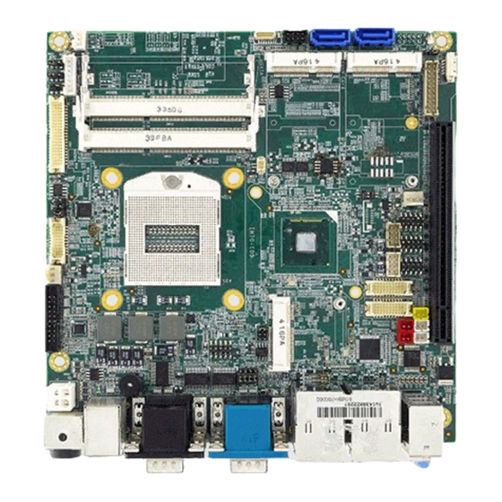
Page 14: Physical Description
User Manual Chapter 1 General Information 1.5 Physical Description Board Dimensions (V120) IV70 Motherboard... -
Page 15: Hardware Installation
Hardware Installation This chapter provides information on how to use jumpers and connectors on the IV70 motherboard. IV70 Motherboard... -
Page 16: Chapter 2 Hardware Installation
Chapter 2 Hardware Installation This chapter provides information on how to use jumpers and connectors on the IV70 Motherboard. Be cautious while working with these modules. Carefully read the content of this chapter in order to avoid any damages. 2.1 Motherboard Components 2.1.1 Front Side... -
Page 17: I/O Side
Hardware Installation 2.1.2 I/O Side 2.2 Memory Module (SO-DIMM) Installation The IV70 SBC Motherboard has two 204-pin SODIMM slot. The socket supports up to 8GB DDR3L 1333/1600 SDRAM. When installing the –memory unit, please follow the steps below: Step 1 Firmly insert the SO-DIMM at an angle of about 30-degree into the slot. Align the SO-DIMM with the slot until it is fully inserted. -
Page 18: I/O Equipment Installation
2.3.2 PS/2 Keyboard and PS/2 Mouse The Motherboard provides two PS/2 interface. The PS/2 connector supports Keyboard 7 IV70 Motherboard User Manual and Mouse. In other cases, especially in embedded applications, a mouse is not used. Therefore, the BIOS standard setup menu allows you to select* “All, But Keyboard”... -
Page 19: Audio Jack ( Pin-Header)
SHORT. The illustration below shows a 3-pin jumper; pins 1 and 2 are short. If you remove the jumper cap, the jumper is OPEN. PIN 1-2 SHORT PIN 3 OPEN CAUTION To avoid damaging the module, always turn off the power supply before setting jumpers or clearing CMOS. IV70 Motherboard... -
Page 20: Jumper List
11-12 JP2: COM1 RS232 / RS422 / RS485 Function Selector The jumper can be configured to operate COM1 in RS-232/422/485 mode. And the setting must be cooperated with the JP1 settings. Pin № Function RS232 (Default RS422 RS485 IV70 Motherboard... - Page 21 Remember to set jumper back to Normal before turning on the power supply. CAUTION TURN OFF the power supply before setting Clear CMOS. Pin № Function Clear CMOS 2-3 (Default) Normal JP6: Brightness Control (VR/Software) Pin № Function VR Control Software JP7: Brightness Control (DC/PWM) Pin № Function DC (VR) IV70 Motherboard...
- Page 22 JP8: Back Light PWR Pin № Function +12V JP9: PWM Level Pin № Function +3.3V JP10: LCD Panel Voltage Select JP10 can be configured to operate in 3.3Volts / 5Volts / 12Volts mode. Pin № Name 1-2* +3.3V +12V IV70 Motherboard...
-
Page 23: Connectors And Pin Assignment
SATA-tP-DIPI80 SIM card connector 6 pin Header DIMM1 / DDR3L Connector DDR3-SODIMM_204P DIMM2 USB1/2 USB PIN HEADER 4x2 header, pitch2.0mm 12V (Yellow) 12V External Power 2x1 header, pitch 2.54mm 5V (Red) 5V External Power 2x1 header, pitch 2.54mm IV70 Motherboard... - Page 24 CN6: 12V Output Pin № Signal Name +12V CN7: Digital I/O Connector Pin № Signal Name Pin № Signal Name Out3 Out1 Out0 Out2 CN8: 5V output Pin № Signal Name CN9: 5V Output Pin № Signal Name IV70 Motherboard...
- Page 25 User Manual Chapter 2 Hardware Installation CN10: Mini PCIe Pin № Signal Name Pin № Signal Name PCIE_WAKE# +V3.3V_MINIPCIE1 +V1.5S CLK_SLOT4_OE# VREG_USIM CLK_PCIE_SLOT4_N CLK_PCIE_SLOT4_P WLAN-RFON2 BUF_PLT_RST2# PCIE_RXN3_SLOT4 +V3.3A PCIE_RXP3_SLOT4 +V1.5S SMB_CLK PCIE_TXN3_SLOT4 SMB_DATA PCIE_TXP3_SLOT4 USB_PN5 USB_PP5 +3.3V_MINIPCIE1 +3.3V_MINIPCIE1 +V3.3_MINIPCIE1 IV70 Motherboard...
- Page 26 Black Light Control 3G/Wi-Fi CN18/ CN19: Mini PCIe Pin № Signal Name Pin № Signal Name PCIE_WAKE# +3.3V BT_EN +1.5V CLK_OE# USIM_PWR USIM_DATA PCIE_CLKM USIM_CLOCK PCIE_CLKP USIM_RESET USIM_VPP Wireless_ENABLE PCIE_RESET PCIE_RXM +3.3V PCIE_RXP +1.5V SMB_CLK PCIE_TXM SMB_DATA PCIE_TXP USB_D- IV70 Motherboard...
- Page 27 Hardware Installation USB_D+ +3.3V +3.3V +1.5V +3.3V +3.3V COM2/ COM5/COM6: Serial port The serial port which is Winbond I/O support is RS232 only. Pin № Signal Name Pin № Signal Name NDCD1A NDSR1A NRXD1A NRTS1A NTXD1A NCTS1A NDTR1A NRI1A IV70 Motherboard...
- Page 28 Chapter 2 Hardware Installation CON1: LVDS Connector Pin № Signal Name Pin № Signal Name LCDVDD LVDS0_TX0_N LCDVDD LVDS0_TX0_P LCDVDD LVDS0_TX1_N LVDS0_TX1_P LVDS0_TX2_N LVDS0_TX2_P LVDS0_CLK_N LVDS0_CLK_P LVDS0_TX3_N LVDS0_TX3_P LVDS1_TX0_N LVDS1_TX0_P LVDS1_TX1_N LVDS1_TX1_P LVDS1_TX2_N LVDS1_TX2_P LVDS1_CLK_N LVDS1_CLK_P LVDS1_TX3_N LVDS1_TX3_P IV70 Motherboard...
- Page 29 User Manual Chapter 2 Hardware Installation CPU_FAN1 / NB_FAN1: FAN Connectors FAN1_NB FAN2_CPU HDD PWR: 5V/ 12V External Power J1/J2: Front Audio IV70 Motherboard...
- Page 30 Signal Name MIC1_L AZ_FOUT_L LINE1_L SW_B LINE2_JD SW_C AUGND AUGND AUGND AUGND AZ_FOUT_R LINE1_R MIC1_R J6: DVI Connector Pin № Signal Name Pin № Signal Name TMDS0- TMDS0+ DDC_CLK DDC_DATA TMDS1- TMDS1+ TMDS2- TMDS2+ CLK+ CLK- HPD2 DVI_EXT_5V DVI_EXT_5V IV70 Motherboard...
- Page 31 TMDS1- TMDS1+ TMDS2- TMDS2+ CLK+ CLK- HPD1 HDMI_EXT_5V HDMI _EXT_5V LPT1: Parallel Port Pin № Signal Name Pin № Signal Name LPT_STB# LPT_PD0 LPT_PD2 LPT_PD1 LPT_PD3 LPT_PD4 LPT_PD5 LPT_PD6 LPT_PD7 ACK# Busy SLCT LPT_AFD# LPT_INIT# ERR# 18-25 LPT_SLIN# IV70 Motherboard...
- Page 32 HD_LED- PW_BT1 RT_BT1 PW_BT2 RT_BT2 RSEV 5VSB SATAI / SATA II: SATA Connector Pin № Signal Name Pin № Signal Name SATA_TXP SATA_TXN SATA_RXN SATA_RXP SIM: SIM Card Connector Pin № Signal Name VREG_USIM MSM_USIM_RESET MSM_USIM_CLK MSM_USIM_VPP MSM_USIM_DATA IV70 Motherboard...
- Page 33 User Manual Chapter 2 Hardware Installation DIMM1 / DIMM2: DDR3L Connector USB1/2: USB PIN HEADER Pin № Signal Name Pin № Signal Name USB_DATA0- USB_DATA1- USB_DATA0+ USB_DATA1+ IV70 Motherboard...
-
Page 34: I/O Side
USB 3.0 USB Type A Video Graphics Array D-Sub 15 2.3.3.1 Audio: Line In/Line Out/Mic Color Signal Blue Line In Green Line Out Pink Microphone 2.3.3.2 COM1: D-Sub 9 Pin № RS232 RS422 RS485 TxD- TxD+ RxD+ RxD- IV70 Motherboard... - Page 35 Pin № Signal Name +12V *Note: Pin 3 is not visible for use 2.3.3.5 LAN1, LAN2: Gigabit Ethernet Pin № Signal Name Pin № Signal Name TX1+ TX1- TX2+ TX2- TX3+ TX3- TX4+ TX4- 2.3.3.6 PSKBM1: PS2 Keyboard/Mouse Connector IV70 Motherboard...
- Page 36 Signal Name Pin № Signal Name USB_D- USB_D+ STDA_SSRX- STDA_SSRX+ GND_DRAIN STDA_SSTX- STDA_SSTX+ 2.3.3.8 VGA: Video Graphics Array Pin № Signal Name Pin № Signal Name GREEN BLUE ID2/RES RED_RTN GREEN_RTN BLUE_RTN KEY/PWR ID0/RES ID1/SDA HSync VSync ID3/SCL IV70 Motherboard...
-
Page 37: Driver Installation
Driver Installation This chapter contains driver installation instructions for IV70 motherboard. IV70 Motherboard... -
Page 38: Chapter 3 Driver Installation
3.1 Chipset Driver Installation Step 1 Insert the CD that comes with the motherboard. Open the file document “Chipset Driver”. Step 2 Double-click “infinst_auto.exe” to install the driver. Step 3 Click on “Yes” to agree with the license terms. IV70 Motherboard... - Page 39 User Manual Chapter 3 Driver Installation Step 4 Click “Next” to install the driver. Step 5 Click “Next” to continue. IV70 Motherboard...
- Page 40 User Manual Chapter 3 Driver Installation Step 6 Click “Yes, I want to restart this computer now“ to continue. IV70 Motherboard...
-
Page 41: Graphic Driver Installation
Chapter 3 Driver Installation 3.2 Graphic Driver Installation IV70 Motherboard is equipped with Intel NM10 Companion Device. The Intel Graphic Drivers should be installed first, and it will enable “Video Controller (VGA compatible). Step 1 Insert the CD that comes with the Motherboard. Open the file document “Graphic Driver”. - Page 42 User Manual Chapter 3 Driver Installation Step 3 Click on “Next” to install the driver. Step 4 Click on “Yes” to agree with the license terms. IV70 Motherboard...
- Page 43 User Manual Chapter 3 Driver Installation Step 5 Click “Next” to continue the installation. Step 6 Click “Next” to continue the installation. IV70 Motherboard...
- Page 44 User Manual Chapter 3 Driver Installation Step 7 Click “Yes, I want to restart this computer now” to continue. IV70 Motherboard...
-
Page 45: Panel Resolution Setting
Driver Installation 3.3 Panel Resolution Setting Step 1 Right-click on the desktop, in the drop-down menu choose Properties. Step 2 In the Display Properties dialog box, go to the Settings tab. Step 3 Go to the Monitor tab. IV70 Motherboard... - Page 46 User Manual Chapter 3 Driver Installation Step 4 Click on “Hide modes that this monitor cannot display” to remove this option. Step 5 Click on “Setting”, then could choose 32bit color qualify. IV70 Motherboard...
-
Page 47: Audio Driver Installation
Step 1 Insert the CD that comes with the motherboard. Open the file document “alc655_driver” and click on “Vista_Win7_R260.exe” to execute the setup. Step 2 Click Yes to install the driver. Step 3 Click “Yes, I want to restart my computer now” to finish installation. IV70 Motherboard... -
Page 48: Ethernet Driver Installation
Driver Installation 3.5 Ethernet Driver Installation The Users must make sure which operating system you are using on the IV70 Motherboard before installing the Ethernet drivers. Follow the steps below to complete the installation of the Broadcom BCM57780 Gigabit Ethernet controller LAN drivers. - Page 49 User Manual Chapter 3 Driver Installation Step 3 Click on “Update Driver” to execute the setup. Step 4 Click on “Browse my computer for driver software” to install driver. IV70 Motherboard...
- Page 50 User Manual Chapter 3 Driver Installation Step 5 Choose the path to install driver. Step 6 Click on “Close” to exit driver installation menu. IV70 Motherboard...
-
Page 51: Intel® Management Engine Software
Platform on which you are installing, and install only those components that matches your platform capabilities. Step 1 Insert the driver CD and select the “Intel ME 9.0” folder and click “Setup.exe” Step 2 Click the checkbox for Install Intel® Control Center & click “Next”. IV70 Motherboard... - Page 52 User Manual Chapter 3 Driver Installation Step 3 Click “Yes” to agree with the License terms. IV70 Motherboard...
- Page 53 User Manual Chapter 3 Driver Installation Step 5 Click “Finish” to complete the software installation. IV70 Motherboard...
-
Page 54: Fintek Com Port Driver Installation
Step 3 Double-click batch file (patch.bat) to install driver. Step 4 Check driver install success. Before the update or update fail. After the update and update success. Step 5 You need to restart your computer. Type in this command from the Run menu: C:\Windows\System32\UserAccountControlSettings.exe or uac IV70 Motherboard... - Page 55 User Manual Chapter 3 Driver Installation To turn off UAC, move the slider to the Never notify position, and then click OK. If you're prompted for an administrator password or confirmation, type the password or provide confirmation. IV70 Motherboard...
- Page 56 To turn UAC back on, move the slider to choose when you want to be notified, and then click OK. If you're prompted for an administrator password or confirmation, type the password or provide confirmation. Restart your computer to turn off UAC. IV70 Motherboard...
-
Page 57: Usb 3.0 Driver Installation (Only For Windows 7)
Step 1 Locate the hard drive directory where the driver files are stored with the browser or the explore feature of Windows*. Step 2 Double click the “Setup.exe” from this directory. Step 3 Click “Next” to continue. IV70 Motherboard... - Page 58 User Manual Chapter 3 Driver Installation Step 4 Read License Agreement and click “Yes” to proceed. Step 5 Review Readme File Information and click “Next” to proceed. IV70 Motherboard...
- Page 59 User Manual Chapter 3 Driver Installation Step 6 When the Setup Progress is complete click “Next” to proceed. IV70 Motherboard...
- Page 60 User Manual Chapter 3 Driver Installation Step 7 Click “Yes, I want to restart this computer now” to finish the installation and restart your computer. IV70 Motherboard...
-
Page 61: Ami Bios Setup
AMI BIOS Setup This chapter describes the different settings available in the AMI BIOS that comes with the board. This chapter offers information on the Award BIOS installation utility. IV70 Motherboard... -
Page 62: Chapter 4 Ami Bios Setup
Display the boot menu. Lists all bootable devices that are connected to the system. With cursor ↑and cursor ↓and by pressing <ENTER>, select the device used for the boot. Pause Pressing the [Pause] key stops the POST. Press any other key to resume the POST. IV70 Motherboard... - Page 63 Goes to the next item Cursor ← Moves to the previous item Cursor → Goes to the next item NOTE: You can press the F1, F2, F3, F4, –/+, and Esc keys by connecting a USB keyboard to your computer. IV70 Motherboard...
-
Page 64: Bios Functions
The advanced menu also uses to set configuration of the CPU and other system devices. There are sub menus on the left frame of the screen. CAUTION Handle advanced BIOS settings page with caution. Any changes can affect the operation of your computer. IV70 Motherboard... - Page 65 User Manual Chapter 4 AMI BIOS Setup 4.2.2.1 PCI Subsystem Settings IV70 Motherboard...
- Page 66 Maximum Payload Set maximum payload of PCI express device or allow system BIOS to select the value(128~4096 bytes) Maximum Read Request Set maximum Read Request size of PCI express device or allow system BIOS to select the value(128~4096 bytes) IV70 Motherboard...
- Page 67 Sleep State). This option may be not effective with some OS. ACPI Sleep State Select the ACPI sleep state the system will enter, when the SUSPEND button is pressed. Lock Legacy Resources Enables or Disables lock of legacy resources. IV70 Motherboard...
- Page 68 User Manual Chapter 4 AMI BIOS Setup 4.2.2.4 Trusted Computing BIOS Setting Description Security Device Support Security Device Support Enable or disable BIOS support for security device. IV70 Motherboard...
- Page 69 Turns on/off the MLC streamer prefetcher. Adjacent Cache Line Prefetch To turn on/off prefetching of adjacent cache lines. TCC Activation offset Offset from the factory TCC activation temperature. Primary Plane Current value The maximum instantaneous current allow for Primary plane. IV70 Motherboard...
- Page 70 SATA Mode Selection This item allows users to select mode of SATA controller(s). SATA Test Mode This item allows users to enable or disable the Test mode. Aggressive LPM Enable PCH to aggressively enter link power state. Support IV70 Motherboard...
- Page 71 User Manual Chapter 4 AMI BIOS Setup Software Feature Mask Configuration 4.2.2.7 Thermal Configuration IV70 Motherboard...
- Page 72 Passive TSP value This value sets the TSP value for the ACPI passive cooling formula. 4.2.2.8 Intel® Rapid Start Technology BIOS Setting Description Intel® Rapid Start This item allows users to enable or disable Intel rapid start Technology technology. IV70 Motherboard...
- Page 73 User Manual Chapter 4 AMI BIOS Setup 4.2.2.9 PCH-FW Configuration This item allows users to enable or disable Me FW image re-flash function. 4.2.2.10 Intel Anti-Theft Technology Configuration IV70 Motherboard...
- Page 74 This item allows users to enable or disable Intel AT in bios for Technology testing only. Intel® Anti-theft Set the number of times recovery attempted will be allowed. Technology Rec 4.2.2.11 Acoustic Management Configuration BIOS Setting Description Automatic Acoustic Option to enable or disable automatic acoustic management. Management IV70 Motherboard...
- Page 75 USB transfer time-out Time-out value for control, bulk, and interrupt transfers. Device reset time-out USB mass storage device starts unit command time-out. Device power-up Maximum time the device will take before it properly report itself delay to the host controller. IV70 Motherboard...
- Page 76 User Manual Chapter 4 AMI BIOS Setup 4.2.2.13 SMART Settings BIOS Setting Description Smart Self Test Enable or disable Run SMART Self Test on all HDDs during Post. 4.2.2.14 F81865 Super IO Configuration IV70 Motherboard...
- Page 77 4.2.2.15 F81865 H/W Monitor BIOS Setting Description Fan1/Fan2 Smart Fan This field enables or disables the smart fan feature. At a certain Control temperature, the fan starts turning. Once the temperature drops to a certain level, it stops turning again. IV70 Motherboard...
- Page 78 Fan1/Fan2 Smart Fan Control. This field enables or disables the smart Enable fan feature. At a certain temperature, the fan starts turning. Once the temperature drops to a certain level, it stops turning again. 4.2.2.17 Intel Smart Connect Technology IV70 Motherboard...
- Page 79 Services (EMS) to allow for remote management of a Windows Server OS. Terminal Type VT-UTF8 is the preferred terminal type for out-of-band management. The next best choice is VT100+ and then VT100. See above, in Console Redirection Settings page, for more Help with Terminal Type/Emulation. IV70 Motherboard...
- Page 80 Disabled: all clocks turned on. Enabled: clocks for empty PCI/PCIe PCI/PCIe clocks slots will be turned off to save power. Lock ICC registers All registers: all ICC registers will be locked. Static only: only static ICC registers will be locked. IV70 Motherboard...
- Page 81 User Manual Chapter 4 AMI BIOS Setup 4.2.2.20 Intel RC Drivers Version Detail 4.2.2.21 CPU PPM Configuration IV70 Motherboard...
- Page 82 This item allows users to enable or disable ACPI T state function. 4.2.2.22 Sandybridge DTS Configuration CPU BIOS Setting Description CPU DTS This item allows users to select the ACPI thermal management uses EC reported temperature value function. IV70 Motherboard...
-
Page 83: Chipset Setting
High Precision Timer Enables or disables the high precision timer. SLP_S4 Assertion Width This item allows users to set a delay of sorts. Restore AC Power Loss This item allows users to select off, on and last state. IV70 Motherboard... - Page 84 PCIe-USB glitch W/A for bad USB device connected behind PCIE/PEG port. Subtractive Decode Enable or disable PCI Express subtractive decode. PCI Express Root Port 1~7 This item allows users to enable or disable the PCI Express Root Port. IV70 Motherboard...
- Page 85 XHCI Mode This item allows user to enable or disable XHCI Mode. EHCI 1/2 Enables or disables the EHCI controller. USB Ports pre-port Disable This item allows users to enable or disable each USB port Control individually. IV70 Motherboard...
- Page 86 User Manual Chapter 4 AMI BIOS Setup 4.2.3.3 PCH Azalia Configuration This item allows user to enable or disable azalea device. 4.2.3.4 BIOS Security Configuration Enable or disable SMI/BIOS/GPIO/BIOS interface/RTC RAM Lock. IV70 Motherboard...
- Page 87 User Manual Chapter 4 AMI BIOS Setup 4.2.3.5 System Agent Bridge Name This item allows users to enable or disable VT-d. 4.2.3.6 Graphic Configuration IV70 Motherboard...
- Page 88 4.2.3.7 NB PCIe Configuration BIOS Setting Description PEG0 - Gen x Select PEG0 speed. Enable PEG This item allows users to enable or disable PEG always. PEG Sampler This item allows users to enable or disable PEG sampler calibrate Calibrate function. IV70 Motherboard...
-
Page 89: Boot
User Manual Chapter 4 AMI BIOS Setup 4.2.3.8 Memory Information 4.2.4 Boot IV70 Motherboard... - Page 90 INT19 Trap Response This item allows option ROMs to trap interrupt 19 Boot Option #1, #2, #3 Selects the boot sequence of the device. Hard Drive BBS Set the order of the legacy devices in this group. Priorities IV70 Motherboard...
- Page 91 Controls the execution of UEFI and legacy storage OpROM. policy Launch Video OpROM policy Controls the execution of UEFI and legacy video OpROM. Other PCI device ROM For PCI device than Network, mass storage or video defines priority which OpROM to launch. IV70 Motherboard...
-
Page 92: Security
This section allows you to configure and improve your system and allows you to set up some system features according to your preference. BIOS Setting Description Administrator Password Sets Setup Administrator Password. User Password Sets User Password. HDD 0: FUJITSU MHY2 Sets the HDD password. IV70 Motherboard... -
Page 93: Save & Exit
Save as User Defaults Save the changes done so far as User Defaults. Restore User Defaults Restore the User Defaults to all the setup options. Reset System with ME ME will run into the temporary disable mode. disable Mode IV70 Motherboard... -
Page 94: Technical Support
Technical Support This chapter contains directory to technical support. IV70 Motherboard... -
Page 95: Chapter 5 Technical Support
We are always ready to give advice on application requirements or specific information on the installation and operation of any of our products. If any problem occurs immediately contact us. 5.1 Drivers The list of drivers available for IV70 Motherboard: Item Driver Windows 10 64bit...
Need help?
Do you have a question about the IV70 and is the answer not in the manual?
Questions and answers