
Related Manuals for Clarke Woodworker CTS10D


Summary of Contents for Clarke Woodworker CTS10D
- Page 1 © 0504 10” TABLE SAW 10” TABLE SAW Model CTS10D Model CTS10D Part Number 6500750 Operating & Maintenance Instructions PRODUCT SERIAL/BATCH NO......
-
Page 3: Table Of Contents
Thank you for purchasing your new CLARKE 10” TABLE SAW, which is designed for DIY, and hobby use ONLY. Before attempting to operate this machine, please read this instruction manual thoroughly and follow all directions carefully. In doing so you will ensure the safety of both yourself and others around you, and, at the same time, you should look forward to it providing long and trouble free service. -
Page 4: Specifications
SPECIFICATIONS Model No ..........CTS10D Part No........... 6500751 Motor ............. 230V~ 50Hz 1ph Power rating ......1.5Kw Speed ........4500 rpm Fuse rating ......... 13Amps Saw Blade ..........10” dia. - 5/8” bore (254x16mm) TCT Maximum depth of cut at 90 .... -
Page 5: General Safety Rules
GENERAL SAFETY RULES WARNING As with all machinery, there are certain hazards involved with their operation and use. Exercising respect and caution will considerably lessen the risk of personal injury. However, if normal safety precautions are overlooked or ignored, personal injury to the operator or damage to property may result. READ and BECOME FAMILIAR with the entire operating manual. -
Page 6: Additional Safety Rules For Table Saws
19. DON’T OVERREACH. Keep your proper footing and balance at all times. For best footing wear rubber soled shoes or boots. Keep the floor clear of oil, scrap wood, etc. 20. WEAR PROPER APPAREL. Loose clothing or jewellery may get caught in moving parts. Wear protective hair covering to contain long hair. -
Page 7: Electrical Connections
ELECTRICAL CONNECTIONS WARNING! THIS APPLIANCE MUST BE EARTHED. Connect the mains lead to a 230 volt (50Hz) domestic electrical supply via a standard 13 amp BS 1363 plug fitted with a 13 amp fuse, or a suitably fused isolator switch. IMPORTANT: The wires in the mains lead are coloured in accordance with the following code: Green &... -
Page 8: Features
This is explained in detail under ‘Mounting the Saw on page 15. NOTE: The stand illustrated is designed specifically for the CTS10D and is available from your Clarke dealer. The Blade Height Adjuster Wheel raises or lowers the blade and may be locked in position by tightening the large ring nut on the adjuster shaft. -
Page 9: Glossary Of Terms
A Mitre Gauge may be used either side of the saw blade, in the groove provided. A Mitre Gauge fence allows workpieces to be held securely at any angle for accurate cross cutting. The Blade Guard protects the operator and must ALWAYS be in place and working properly. -
Page 10: Unpacking And Checking Contents
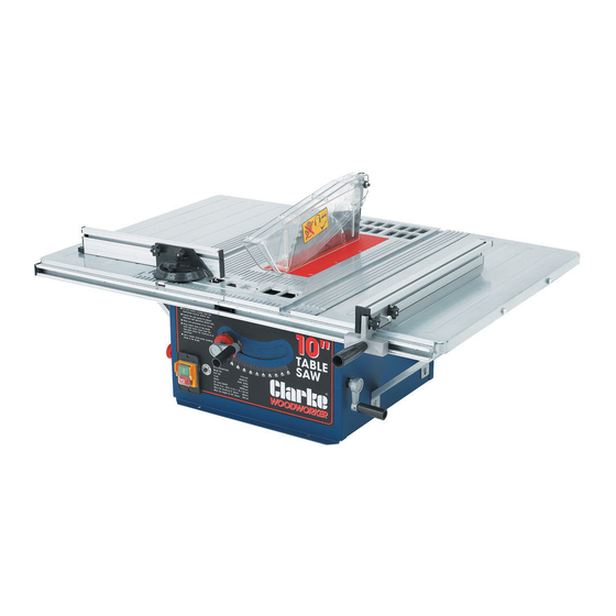
CLARKE Customer Service Department on 020 8558 7400 Fig.1 Note: The Saw is shown, mounted on the optional Stand, available from your Clarke dealer. We strongly recommend the stand be used for stability and to increase the level of safety. -
Page 11: Assembly Instructions
Mitre Gauge Fence* Rip Fence Handle These may be attached to the respective fences These items may be pre-assembled *** T his item may be assembled to machine Should any component be deficient, or damaged, please contact you Clarke dealer immediately... - Page 12 A. Table Extension Carefully invert the saw assembly so that it rests on its table on a firm, level surface and remove the bottom grille - 4 securing screws. Remove the polystyrene motor support (used for transit purposes). Attach 4 Table Extension Support struts, each with a single M6x15 bolt (A), with flat washer on the inside, and flat and spring washer on the outside against the strut.
- Page 13 D. Riving Knife Remove the Table Insert (8 countersunk head screws). Raise the blade to its fullest extent..it is helpful also, to turn the angle adjuster so as to lay the blade on its side to some degree IMPORTANT: Take great care to avoid contact with the saw teeth which are extremely sharp when performing the following operations.
- Page 14 Fig.8 E. Blade Guard Attach the Blade Guard to the Riving Knife, as shown in Fig. 8, ensuring the large plastic washer (B) is used. Tighten the self locking nut (A) sufficiently for the Guard to be secure, but capable of dropping fully under its own weight.
-
Page 15: Mounting The Saw
If the table saw is to be used in a permanent location, it should be fastened securely to a firm supporting surface such as a stand or workbench, using the four mounting holes in the base. A Floor Stand, specially designed for your CTS10D Table Saw is available from your CLARKE dealer . -
Page 16: Important Checks Before Starting
IMPORTANT CHECKS - BEFORE STARTING IMPORTANT: Before attempting to use the machine, it is necessary to ensure the various components are correctly adjusted, and checked for security. ALWAYS raise the blade and check for security. Ensure the Blade Guard is fitted and is secure, capable of dropping under its own weight. Remove all tools or pieces of wood from the table. -
Page 17: Rip Cutting
2. Ripping or Rip Cutting Fig.12 This is the term used for cutting timber in the same direction as the grain, i.e usually lengthwise. To assist in producing a straight, true cut, a RIP FENCE is used. This may be positioned to the right or left of the saw blade, and may be adjusted to suit the width of cut required, and firmly secured in place, ensuring it is parallel to the blade, by... -
Page 18: Crosscutting
PUSH STICK AND PUSH BLOCK 304mm Make the Push Block using pieces of 10mm plywood and 19mm hardwood as shown in Fig.10. The small piece of wood 10x10x64mm should be GLUED to the plywood. DO NOT USE NAILS or SCREWS. This is to prevent damaging the saw blade 130mm 10mm in the event you mistakenly cut into the push block. -
Page 19: Repetitive Cutting
The graduations on the mitre gauge provide accuracy for average woodworking. In some cases where extreme accuracy is required, when making angle cuts for example, make a trial cut and then recheck it with an accurate square or protractor. For maximum accuracy when using the mitre gauge, always favour one side of the groove in the table. -
Page 20: Mitre Cutting
Slide the workpiece along the mitre gauge until it touches the block, hold it securely. When cutting long workpieces, make sure the end is supported - from the floor. Make the cut, pull the workpiece back and push the cut-off piece off the table with a long push stick, DO NOT ATTEMPT TO PICK IT UP AS THIS COULD ENDANGER YOUR HANDS WARNING! NEVER USE THE RIP FENCE AS A LENGTH STOP BECAUSE THE CUT-OFF PIECE COULD BIND... -
Page 21: Maintenance
A coat of wax applied to the table will help to keep the surface clean and allow workpieces to slide more freely. 1. Changing the Blade IMPORTANT: 1. Use only Clarke Blade, (see parts list for part numbers). 2. Replace the blade when teeth become damaged or dull. WARNING! 1. -
Page 22: Saw Blade Adjustments
2. Adjusting 90 and 45 Degree Positive Stops WARNING! ENSURE THE PLUG IS DISCONNECTED FROM THE POWER SUPPLY BEFORE PROCEEDING 2A. Adjusting Positive Stop at 90 Degrees Fig.22 Raise the blade to maximum height. (ii) Turn machine so that it rests on its back edge, and (iii) Turn the blade angle adjusting handle until it hits the 90... -
Page 23: Trouble Shooting
TROUBLE SHOOTING TROUBLE PROBABLE CAUSE REMEDY Saw will not start 1. Saw not plugged in 1. Plug in the machine 2. Fuse blown or circuit breaker 2. Replace fuse or reset circuit tripped breaker 3. Power cable damaged 3. Have cable replaced by authorised service centre Does not make 1. -
Page 24: Parts Lists And Diagrams
PARTS LISTS No. Description Part No No. Description Part No Connecting Bolt CTS10D001 Bearing CTS10D044 Flat Washer CTS10D002 Gear Shaft CTS10D045 Blade Guard CTS10D003 CTS10D046 CTS10D004 Gear CTS10D047 Riving Knife CTS10D005 Retaining Ring CTS10D048 Locking Knob CTS10D006 Gear Box CTS10D049 Washer CTS10D007 Screw... - Page 25 CTS10D107 PARTS AND SERVICE CONTACTS For Spare Parts and Service, please contact your nearest dealer, or CLARKE International, on one of the following numbers. PARTS & SERVICE TEL: 020 8988 7400 PARTS & SERVICE FAX: 020 8558 3622 e-mail as follows: PARTS: Parts@clarkeinternational.com...
- Page 26 PARTS DIAGRAM...
Need help?
Do you have a question about the Woodworker CTS10D and is the answer not in the manual?
Questions and answers