
Related Manuals for Emerson Liebert CRV


Summary of Contents for Emerson Liebert CRV
- Page 1 Precision Cooling For Business- Critical Continuity ® Liebert 10-50 kW A/W/C, 50 Hz Versions USER MANUAL 273870 English Cod. Rev. 11.10.2013 Refrigerant R410A proper tools...
- Page 3 IMPORTANT SAFETY INSTRUCTIONS SAVE THESE INSTRUCTIONS CAUTION The manual is retained for the entire service life of the machine; The user reads the manually carefully before carrying out any operations on the machine; The control is used exclusively for the purpose for which it is intended; incorrect use of the control shall release the manufacturer any liability.
- Page 4 WARNING Risk of refrigerant system rupture or explosion from overpressurization. Can cause equipment damage, injury or death. If a pressure relief device is not provided with the condenser unit, the system installer must provide and install a discharge pressure relief valve rated for a maximum of 609 psig (42bar) in the high side refrigerant circuit.
- Page 5 DATA PLATE MODEL AND SERIAL NO. Attention: data relevant to the supplied unit are indicated on the inboard label (see below empty fax-simile). Data in the manual are referred to stan- dard conditions and can be modified wi- thout any advance notice. FRONT VIEW Data plate fac-simile for 50 Hz units, CE marked...
- Page 6 C R 0 1 0 Digit 1 and 2 Digit 3, 4 and 5 Family Size: Cooling Capacity “kW” (approx.) Liebert CRV Nominal Cooling Capacity Digit 6 - Air Discharge Digit 15 - Coil Air Discharge Horizontal airflow Coil - Air cooled - water cooled two ways water valve...
-
Page 7: Table Of Contents
INDEX IMPORTANT SAFETY INSTRUCTIONS ............SAVE THESE INSTRUCTIONS . - Page 8 10.0 Maintenance / Spare Parts ............. . 10.1 Safety instructions .
-
Page 9: Important Safety Instructions
± 0.05 m ± 0.05 m ± 0.10 m 0.54 0.30 0.75 0.52 0.30 0.71 0.50 0.30 0.80 0.54 0.30 0.80 0.54 0.30 0.80 The center of gravity on the Liebert CRV varies with the options and the model’s size. -
Page 10: Operating Limits
Preliminary Operations Fig. a - Unit handling weight ± 5% [kg] Air-cooled Water/Glycol-cooled 400/3/50 400/3/50 400/3/50 Chilled water 400/3/50 400/3/50 Weights of full version units without packaging Operating limits The units are designed to operate within working ranges (see Tab. a). These limits are referred to new machines or to those that have been correctly installed and ser... -
Page 11: Noise Level Limits
Remote Condenser To ensure correct operation, best performance, and longest life the units must be connected to remote condensers approved by Emerson Network Power. The warranty clauses are no longer valid if unit is connected to a not approved remote condenser. -
Page 12: Product Description
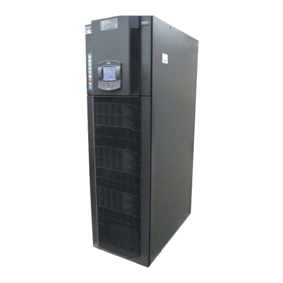
Unit without iCOM Display iCOM Display The Liebert CRV is a range of full-featured compressorized (air, water, glycol cooled) and chilled water cooling units to be installed within a row of high density computing racks in a “hot-aisle-cold- aisle“ configuration. - Page 13 Fig. d - Component location Liebert CRV Air-cooled (A), Water/Glycol-cooled (W), Chilled water (C) units iCOM Control...
- Page 14 Preliminary Operations Fig. e - Component location Liebert CR010-020-035 Air - cooled (A) units Termostatic ex pansion valve Solenoid valve Sight glass Filter dryer Liquid receiver Safety valve Humidity/Temp. sensor Humidifier Top refrigerant connections Bottom refrig. connections È È È È È È È È È È È È È È È È...
- Page 15 Preliminary Operations Fig. g - Component location Liebert CR040-050 Chilled water unit Top CW connections Filters Three way CW valve Bottom CW connections Humidifier Unit with 3 fans Unit with 2 fans...
-
Page 16: Positioning - Unit Placement
1. Placement in the row of racks For single row application with one Liebert CRV unit it is not preferred to put the unit in the middle of the row because of possible hot spots at top part of racks, unless in combination with CoolFlex or in application with more Liebert CRV units. - Page 17 Positioning - unit placement 2. Number of racks / length of the row Standard application with one Liebert CRV unit is with 2-6 racks. The exact number of racks depends on size of Liebert CRV unit used and heat load per rack. Whenever...
- Page 18 Not advised approach: As you can see on CFD result above, it is not advised to place Liebert CRV at the wall in single row layout. On the contrary, it is not an issue in application with two rows and two or more Liebert CRV units.
- Page 19 Following an example of more complex applications where N+1 redundancy provided. Please note the number and size of Liebert CRV units have to be designed in order to achieve required cooling capacity if any of the units fails. The other option to easily achieve redundancy is CoolFlex (Cold aisle containment), see point 5 below.
- Page 20 Please find following an example layout of typical installation with two rows of racks with Liebert XDV modules. Two Liebert CRV units are used to support the Liebert XD system and to ensure N+1 redundancy on humidity control. See also CFD result showing site view of the room.
-
Page 21: Unpacking And Installation
Unpacking and installation Unpacking and installation NPACKING AND INSTALLATION Reference guide for receiving, unpacking, and preparing for installation. DO NOT THROW AWAY! WARNING RISK OF TOP HEAVY UNIT FALLING OVER! IMPROPER HANDLING CAN CAUSE EQUIP MENT DAMAGE, INJURY, OR DEATH! READ ALL OF THE FOLLOWING INSTRUCTIONS BEFORE ATTEMPTING TO MOVE, LIFT, REMOVE PACKAGING FROM, OR PREPARING UNIT FOR INSTALLATION. -
Page 22: Unpacking The Unit
Unpacking and installation S When handling the packaged unit with a fork lift or pallet jack, the unit shall not be lifted any higher than 51102 mm off the ground. All bystanding personnel shall be no closer than 3.7 m to the handled packaged unit. S If circumstances require the unit to be lifted higher than 102 mm great care shall be excercised and all bystanding personnel are to be no closer than 5 m to the lift point of the unit. - Page 23 Unpacking and installation S Acquire a set of piano jacks rated to properly handle the unit weight and size. S Raise the forks of the piano jacks to contact the bottom of the unit base. S Place the piano jacks against unit as shown. Place, nonabrasive, protective material...
-
Page 24: Removal Of Piano Jacks
Unpacking and installation Removal of Piano Jacks S Remove the piano jack strapping and care fully pull the piano jacks away from the unit. S Remove all material used for panel protec tion. S Unit is now resting on the wood spacer boards. -
Page 25: Installation
Unpacking and installation Installation 1. Opening the frontup panel, there are: S serial number of the unit for service (a) Using a screwdriver open the electrical panel and the front down panel to prepare installation: Using the keys (b) make the same on the rear. The documents are on reardown vain (c). 2. - Page 26 4. Before Startup adjust the frontal panel baffles to give right air flow direction. This operation is very important to obtain the maximum efficiency from Liebert CRV unit and to prevent rack’s overheating in the system. For any doubt contact Liebert Service people.
- Page 27 Unpacking and installation Turn the baffles (if necessary) to direct right or left the air flow Remove the screws (1 on left and 1 on right side) Disassemble only the wrong baffles Rotate around a horizontal axle to adjust direction Reassemble and lock the screws 5.
-
Page 28: Refrigeration Connections
Refrigeration Connections Refrigeration Connections EFRIGERATION ONNECTIONS Use only condenser unit design for R410A refrigerant The unit is designed both from top and bottom side. Refrigeration pipeline connections Air - cooled (A) units Top refrigeration pipeline connections Bottom refrigeration pipeline connections: if you are using botton ones, de-braze pipes across square dot line and re- move pipes to the top of the unit. -
Page 29: Pipe Diameter And Thickness
Tab. b - Condenser positioning CONDENSER AND CONDENSER BELOW CONDENSER CONDENSER ABOVE CONDITIONER CONDITIONER POSITION CONDITIONER AT SAME LEVEL (not recommended) int. necessary necessary necessary ext. only for aesthetic reasons only for aesthetic reasons only for aesthetic reasons SULA- no (expose to cold int. - Page 30 Refrigeration Connections S soft copper: by hand or bending device. S hard copper: use preformed curves. Do not overheat the pipes when brazing so as to minimize oxidation. 2) Connect the pipes to the condenser: S Condensers with butt-brazed pipe connections: cut the pipe, enlarge it and braze it to the pipeline.
-
Page 31: Vacuum Creation And Refrigerant Charge
Refrigeration Connections Vacuum creation and refrigerant charge Check the refrigerant type to be used on the data plate of the air conditioner and on the refrigerating compressor. Fig. i - Pump and refrigerant charging cylinder connection for vacuum creation and refrigerant charge R.L. -
Page 32: R410A Precharge Air - Cooled (A) Units
Refrigeration Connections 4.2.1 R410A precharge Air - cooled (A) units 1) Open all cocks of the system including those used for pressurizing (ambient unit and condens- ing unit). By this operation all the components of the refrigerating circuit must be subject to vacuum. 2) Connect a proper, high efficiency vacuum pump (10) suitable for polyester oils to the coup- lings: Compressor intake and delivery using, if available, the three-way Rotalock cocks, coup-... -
Page 33: Water Connections
Water Connections Water Connections ATER CONNECTIONS OPTION TOP connections DOWN connections. Condensate pump + humidifier Available choice Available choice Condensate pump Available choice Available choice Humidifier single choice Nothing (drain only) single choice Top connections: e) supply and drain water connection (all types unit). f) chilled water (C unit) or cooling water (W unit) connections. -
Page 34: Chilled Water Connections Water/Glycol - Cooled (W) Units
S It is advisable to use hoses to be connected, with 3-piece joints, to the condenser water inlet and outlet couplings. S Install a 16-20 mesh strainer on the chilled water supply to the Liebert CRV. The strainer is needed to prevent particles in the chilled water from entering the heat exchanger of the Liebert CRV. -
Page 35: Notes For Open Circuit Applications
Water Connections 5.3.1 Notes for open circuit applications S Use the unit with mains or well water. DO NOT USE WATER FROM AN EVAPORATIVE COOLING TOWER UNLESS THE FILLING WATER HARDNESS IS CONTROLLED. S The water pressure must be 2 - 10 bar (if this is not so, contact the Technical Support Depart- ment). - Page 36 Water Connections Advised Dry cooler Installation Fig. l - filling water disconnect after charge Stand---by pump APPLIANCE (optional) Stand---by pump shut-off valve thermostat air separator } (*) Variex (opt.) charge group (filter, pump reducer, check valve) check valve safety valve filling meter manometer expansion tank...
-
Page 37: Electrical Connections
Electrical Connections Electrical Connections LECTRICAL ONNECTIONS Electrical connections Use cable ties to fix high and low voltage wires to plastic clamps Low voltage signal entry port (g) Power supply entry port (h) Routing cables from the floor. Routing cables from the top. 1) Before proceeding with the electrical connections, ensure that: S all electrical components are undamaged;... -
Page 38: Protective Features Of Ec Fan
Electrical Connections Protective features of EC fan The EC fan has been provided with the following protective fea- tures: S Over temperature of electronics S Over temperature of motor S Locked rotor protection S Short circuit at the motor output With any of these failures, the motor stops (electronically - no po- tential separation), the status relay is released. - Page 39 Liebert 2T Sensor Placement Guidelines The Liebert 2T sensors come with the Liebert CRV unit to help avoid any problem spots in the row. Using the rack sensors can help combat cooling problems users experience related to: recirculation air, uneven rack loading, and air distribution.
- Page 40 Electrical Connections Temperature remote sensor --- THB type Fig. n - SENSOR POSITION IN FRONT OF THE RACK FIRST SENSOR CABLE CONNECTION SENSOR CHAIN TOP INLET FRONT VIEW BOTTOM INLET (possible with raised floor)
- Page 41 Electrical Connections Temperature remote sensor --- 2T type Fig. o - TEMPERATURE SENSOR 1 (Install temperature sensors on DOOR the perforated portion of the rack RACK door using the supplier zip-ties) POST OF THE RACK EARTH WIRE CAGE SCREW VELCRO 2T SENSOR HOUSING TEMPERATURE SENSOR 2...
-
Page 42: Start-Up
Start-up Start-up TART-UP First start-up (or after long standstill) TO PREVENT COMPRESSOR DAMAGE THE CRANKCASE(S) MUST BE PREHEATED FOR AT LEAST 4 HOURS BEFORE CONDITIONER START-UP (FAILURE TO DO SO INVALID- ATES THE GUARANTEE). Start the air conditioner as follows: 1. -
Page 43: Automatic Restart
Checking the refrigeration piping pressure drops Liebert CRV is equipped with connections to check the refrigeration piping pressure drops: room unit → condenser → room unit To carry out this operation it is necessary to use 2 calibrated manometers and connect them as follows: M1, connected to the compressor delivery valve;... -
Page 44: Operation
Operation Operation PERATION Unit operation is completely automatic. The below sequence explains how the unit operates : S The air, sucked in by the fans, which operate continuously, enters the unit. S The air is immediately filtered. S The TEMPERATURE sensor or HUMITEMP (temperature + rel. humidity) sensor (check type installed), verifies the state of the inlet air, and relays this information to the control sys- tem. -
Page 45: Calibrations & Regulation (At Start-- Up)
Calibrations & Regulation Calibrations & Regulation ALIBRATIONS & EGULATION (AT START-UP) The air conditioner has already been factory-tested and calibrated, but it is very important to check, at start-up, the superheating of thermostatic valve (A/W versions). S The air conditioner has already been factory. S For calibrations of instruments installed on the external condensers/Dry coolers refer to the relevant manual. -
Page 46: Safety Instructions
10.2 Spare parts Only original spare parts made by Emerson Network Power may be used. Using third-party mater- ial can invalidate the warrantee. When making inquiries always refer to the "Component List" supplied with the equipment and specify the model number, serial number and, if available, the part number as well. -
Page 47: Air Filter Check Or Substitution
Maintenance / Spare Parts 10.4 Air filter check or substitution Every month it’s important to check the state of air filter to maintain a good efficiency of air distri- bution throw the evaporator coil. First switch off the CRV, then open the rear panel with the key, access to the fan panel rotating the three locks with the black key. -
Page 48: Condensate Drain And Condensate Pump Systems
Maintenance / Spare Parts 10.5 Condensate Drain and Condensate Pump Systems 10.5.1 Condensate Drain Check and clear obstructions in tubing during routine maintenance 10.5.2 Condensate Pump S Disconnect power to unit using disconnect switch. S Check and clear obstructions in gravity lines leading to condensate pump. S Remove sump and clean with a stiff nylon brush and flush with water. -
Page 49: Refrigeration Circuit
Maintenance / Spare Parts MAINTENANCE PERIOD EVERY COMPONENT COMPONENT Check cylinder & pan STEAM GENER- Check steam hoses conditions ATING HUMIDIFI- Verify filling solenoid valve proper operation Circuit leakage/general condition check COOLING WATER Check water(-glycol) inlet temperature CIRCUIT Check water regulating valve operation Check in/out water(-glycol) ∆t (W and C units) Check mixture glycol level (if applicable) -
Page 50: Oil Topping ---Up Of An Installed Circuit
Maintenance / Spare Parts These oils rapidly absorb the humidity present in the air when they are exposed to the atmosphere. If the oil absorbs humidity, the ester molecules can break down, forming acidity. We therefore recommend exposing the oil for as short a time as possible (no more than a few minutes) and, in case of topping up, using exclusively the oil indicated on the refrigerating com- pressor. - Page 51 Maintenance / Spare Parts S Direct methods of leakage checking approved by the manufacturer (Reg. 1516/2007 and Reg. 1497/2007) a. gas detection device adapted to the refrigerant in the system; the sensitive of portable gas detection devices (as a direct test method) shall be at least five grams par year. b.
-
Page 52: Unit Diagnostic
Maintenance / Spare Parts 10.11 Unit diagnostic PROBLEM POSSIBLE CAUSE CORRECTIVE ACTION Dirty filters Replace filters False filter clogs Call Liebert Service Incorrect positioning of remote temperature Verify remote temperature sensors sensor/s correct positioning Remote temperature sensor/s issue Call Liebert Services (A units) verify remote condenser fan/ s are running (W units) check cooling water supply... -
Page 53: Humidair Humidifier
App. A - Humidair humidifier App. A - Humidair humidifier App. A H UMIDAIR HUMIDIFIER App. A.1 Preface The HUMIDAIR represents the best humidifier technology available, guaranteeing the steam as clean as possible together with simple maintenance. In order to obtain optimum performance from the HUMIDAIR it is advisable to read this manu- al carefully. - Page 54 App. A - Humidair humidifier Fig. b Drain water connection WATER DRAIN TUBING It is supplied a hose with an integ- ral drain trap. DISMANTLE DRAIN TRAP. S DO NOT DISMANTLE THE DRAIN TRAP . S The hose is already fitted onto the humidifier drain outlet (K).
- Page 55 App. A - Humidair humidifier App. A.4 Start-up and operation App. A.4.1 Start-up Before using the humidifier, check the following: Supply and drain connections. That the cut-off tap is open. All wiring. Earthing. Steam hose connection between steam cylinder and distributor. To start the humidifier simply switch on the air conditioner, which will in turn automatically start and stop the humidifier as required.
- Page 56 App. A - Humidair humidifier App. A.5.3 Annual maintenance Annually (e.g. before any close-down period) carry out the following service on the humidifier (see Fig. c): Carry out the instructions in para. App. A.5.1. Disconnect the supply (F) and drain (D) valve wires. Unscrew and remove the drain tank (T).
-
Page 57: Technical Data Table
Technical data table Technical data table Tab. 1 - Electrical data RESIDUAL-CURRENT CIRCUIT Power Configuration Model supply BREAKERS Inn = 0.3A (400V) (*) 20 A Curve C CR010 Cooling 22.3 40 A Curve C CR020 Fan + compressor 28.0 50 A Curve C CR035 17.0 25 A Curve C... - Page 58 Technical data table Tab. 3 - Calibrations of electrical components Refrigeration Circuit Item COMPONENT SETTING NOTES Contact Range 0-45 barg High Pressure 18--- 19 Transducer Output 0-5V (see iCom manual) Range 0-17.3 barg Low Pressure Transducer Output 0-5V (see iCom manual) STOP 37.0±1 barg START 30.0±1.5 barg...
- Page 59 N.B.: The air conditioner is supplied complete with refrigerant and oil. (1) The recommended oil is EMKARATE RL 32--- 3MA. (2) For distance D see Fig. 1. Tab. 6 - Liebert CRV Sound Data The following tables show sound levels for every octave band frequency. CR010 Air Cooled Tested...
-
Page 60: Installation Drawing
Installation Drawing Installation Drawing Fig. 1. OVERALL DIMENSIONS / SERVICE AREA REAR VIEW FRONT VIEW ACCESS REQUIRED TO SERVICE WITHIN ROW ATTENTION REAR SERVICE AREA UNIT IS S+B OR S+A WHEN B IS NOT AVAILABLE TOP VIEW ACCESS REQUIRED TO REMOVE FROM ROW C - 1... - Page 61 Installation Drawing Fig. 2. HOLE ON THE RAISED FLOOR FOR PIPING AND ELECTRICAL CONNECTIONS FRONT VIEW UNIT AREA 195.5 324.5 UNIT AREA 31.5 154.5 4 (2 3/16”) 55.5 544.5 FRONT VIEW C - 2...
- Page 62 Installation Drawing Fig. 3. AIR BLEEDING VALVE POSITION CW REAR VIEW Fig. 4. ELECTRICAL CONNECTIONS - ENTRY TOP INLET FRONT VIEW BOTTOM INLET (possible with raised floor) C - 3...
-
Page 63: Refrigerant, Hydraulic And Electrical Connections
Refrigerant, Hydraulic and Electrical Connections Refrigerant, Hydraulic and Electrical Connections Fig. 1. CR010RA - CR020RA - CR035RA connections Unit with 1 fan Unit with 2 fans REAR VIEW TOP CONNECTIONS 247.5 324.5 225.5 HF/HD 76.5 CD or DP EC- - HV EC- - HV EC- - LV EC- - LV... - Page 64 Refrigerant, Hydraulic and Electrical Connections Fig. 2. CR010RW - CR020RW - CR035RW connections Unit with 1 fan Unit with 2 fans REAR VIEW TOP CONNECTIONS 247.5 324.5 225.5 HF/HD 76.5 EC- - HV CD or DP EC- - LV EC- - HV EC- - LV 55.5 BOTTOM CONNECTIONS...
- Page 65 Refrigerant, Hydraulic and Electrical Connections Fig. 3. CR040RC - CR050RC connections Unit with 2 fans Unit with 3 fans REAR VIEW 247.5 324.5 TOP CONNECTIONS 225.5 (8 7/8") HF/HD 76.5 EC- - HV CD or DP EC- - LV EC- - HV EC- - LV BOTTOM CONNECTIONS 55.5...
- Page 66 Refrigerant, Hydraulic and Electrical Connections Fig. 4. Electrical board layout SPRING TERMINALS WKMF 2.5/15 Wire bridge SPRING TERMINALS WKMF 2.5/15 D - 4...
- Page 67 Refrigerant, Hydraulic and Electrical Connections ELECTRICAL FIELD CONNECTIONS DESCRIPTIONS - 50 Hz STANDARD ELECTRICAL CONNECTIONS Primary high voltage entrance - 64mm; 44mm; 35mm diameter concentric knockouts located in bot- tom of box Secondary high voltage entrance - 64mm; 44mm; 35mm diameter concentric knockouts located in top of box Primary low voltage entrance - Quantity (3) 28mm diameter knockouts located in bottom of unit Secondary low voltage entrance - Quantity (3) 28mm diameter knockouts located in top of box...
-
Page 68: Refrigeration & Hydraulic Circuits
Refrigeration & Hydraulic Circuits Refrigeration & Hydraulic Circuits Fig. 1. LIEBERT CRV: CR010RA - CR020RA - CR035RA (on CR035 only) (external on: CR010 and CR020) (to disconnect for bottom connections) POS. POS. DESCRIPTION DESCRIPTION Compressor Check valve Crankcase heater Shut--- off valve... - Page 69 Refrigeration & Hydraulic Circuits Fig. 2 - LIEBERT CRV: CR010RA - CR020RA - CR035RA (with EEV valve) (on CR035 only) (external on: CR010 and CR020) REMOTE CONDENSER (to disconnect for bottom connections) POS. POS. DESCRIPTION DESCRIPTION Compressor Check valve Crankcase heater...
- Page 70 Refrigeration & Hydraulic Circuits Fig. 3. LIEBERT CRV: CR010RW - CR020RW - CR035RW (on CR035 only) (external on: CR010 and CR020) (on CR010 and CR020 only) WATER/GLYCOL OUTLET (top connections) WATER/GLYCOL OUTLET (bottom connections) (only with WATER/GLYCOL INLET (top connections)
- Page 71 Refrigeration & Hydraulic Circuits Fig. 4 - LIEBERT CRV: CR010RW - CR020RW - CR035RW (with EEV valve) (on CR035 only) (external on: CR010 and CR020) (on CR010 and CR020 only) WATER/GLYCOL OUTLET (top connections) WATER/GLYCOL OUTLET (bottom connections) (only with...
- Page 72 Refrigeration & Hydraulic Circuits Fig. 5. LIEBERT CRV: CR040RC - CR050RC CHILLED WATER INLET (top connections) (only with optional 2 ---way valve) CHILLED WATER OUTLET (top connections) CHILLED WATER OUTLET (bottom connections) CHILLED WATER INLET (bottom connections) POS. Components POS.
- Page 73 Fabricante --- Tillverkare --- Fabrikant --- Valmistaja --- Produsent Fabrikant --- Κατασκεναστηζ --- Producent Emerson Network Power S.r.l. --- Zona Industriale Tognana Via Leonardo da Vinci, 16/18 --- 35028 Piove di Sacco --- Padova (Italy) Il Fabbricante dichiara che questo prodotto è conforme alle direttive Europee: The Manufacturer hereby declares that this product conforms to the European Union directives: Der Hersteller erklärt hiermit, dass dieses Produkt den Anforderungen der Europäischen Richtlinien gerecht wird:...
- Page 74 Specifications subject to change without notice. EmersonNetworkPower.eu Emerson, Business- -Critical Continuity and Emerson Network Power are trademarks of Emerson Electric Co. or one of its affiliated companies. 2013 Emerson Electric Co. EMERSON. CONSIDER IT SOLVED.
Need help?
Do you have a question about the Liebert CRV and is the answer not in the manual?
Questions and answers