
Related Manuals for Emerson XEV22D


Summary of Contents for Emerson XEV22D
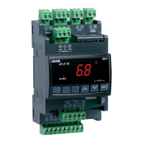
- Page 1 026-1206 Rev 3 13-DEC-2012 XEV22D Driver for Stepper Electronic Expansion Valves Installation and Operation Manual...
- Page 3 Emerson Climate Technologies Retail Solutions 1065 Big Shanty Road NW, Suite 100 Kennesaw, GA 30144, USA Phone: 770-425-2724 Fax: 770-425-9319...
-
Page 5: Table Of Contents
5.2. P XEV22D ............................. 4 OWERING THE 5.2.1. Choosing Transformer Sizes ..........................4 5.2.2. XEV22D Power Wiring............................5 5.2.3. Wire Type and Maximum Distances ........................5 6 VALVE CONNECTIONS AND CONFIGURATION ....................6 7 ABSOLUTE MAXIMUM POWER ..........................8 8 FRONT PANEL ................................9 8.1. - Page 6 19.3.1. Set Up Network Ports............................23 19.3.2. Add and Connect the Device ..........................23 19.4. W ................................25 IRING YPES 19.5. MODBUS T ........................... 25 ERMINATION LOCKS 20 STANDARD VALUES .............................. 26 vi • XEV22D I&O Manual 026-1206 Rev 3 13-DEC-2012...
-
Page 7: Introduction
1.1. General Warning 2.1. General Description Please read the following safety precautions and The XEV22D controller is capable of driving a warnings before using this manual: wide variety of stepper electronic expansion valves. The controller regulates the superheat (SH) of the flu-... -
Page 8: Wiring Connections
The superheat regulation is performed only when the cooling digital input is enabled. Figure 3-1 shows how the device takes the request of cooling: Figure 3-1 - How XEV22D Acts on Cooling Request See Figure 3-2 for wiring. The “First Level” indicates the connections on the floor of the 4-DIN module and “Second Level”... -
Page 9: Wiring Guidelines
Wiring Guidelines DEVICE TYPE RETAIL SOLUTIONS ANALOG TEMP SENSOR BELDEN #8761 #22-2 SHIELDED DIGITAL INPUT Retail Solutions P/N 035-0002 RS-485 NETWORK BELDEN #8761 #22-2 SHIELDED Retail Solutions P/N 035-0002 BELDEN #8641 #24-2 SHIELDED Retail Solutions P/N 135-8641 PRESSURE TRANSDUCER **BELDEN #8771 #22-3 SHIELDED Retail Solutions P/N 135-8771 **#8771 for alternate 600v rated wire use BELDEN #8618 16 *STEPPER VALVE... -
Page 10: Mounting And Powering
Mounting and In some instances, an installer may be required to mount the XEV22D. There are no restrictions on the Powering location of the XEV22D; however, the controller should be mounted in a location protected from mois- ture. Typically, mounting inside the electrical control panel of a package unit is acceptable. -
Page 11: Xev22D Power Wiring
18 AWG: 9ft. (rounded down) 5.2.2. XEV22D Power Wiring Sensors requiring 24VAC should not be powered The XEV22D can be powered by one of the 50VA from the same transformer powering the input board. non-center-tapped transformers listed in Table 5-2. -
Page 12: Valve Connections And Configuration
In any case, the unique and valid reference has to be considered the datasheet made by manufacturer of the valve: Connection SPORLAN ALCO EX* DANFOSS ETS Numbering SEI-SEH BLUE WHITE BLACK BROWN BLACK WHITE BLACK WHITE GREEN GREEN Table 6-2 - 4-Wire Valves (Bipolar) 6 • XEV22D I&O Manual 026-1206 Rev 3 13-DEC-2012... - Page 13 XEV22D controller must not exceed 30 stant current valve driver. XEV controllers use a feet (10 meters).
-
Page 14: Absolute Maximum Power
9. If step 8 reading was less than 0.3A, power down the XEV22D and move the meter red lead from the NOTE: The electrical power absorption of the meter 10A terminal to the meter 400 mA or 300mA valve can be unrelated to refrigeration power terminal. -
Page 15: Front Panel
Front Panel Function To lock and unlock the keyboard. To enter programming mode. Table 8-1- XEV22D Front Panel Keys and Functions 8.2. XEV22D LEDS Each LED function is described in Table 8-2: Mode Function Low pressure alarm Maximum operating pres-... -
Page 16: User Interface
NOTE: The set value is stored even when the time-out expires and ends the procedure. 1. Press the SET + DOWN arrow keys for about 3 sec- onds. 10 • XEV22D I&O Manual 026-1206 Rev 3 13-DEC-2012... -
Page 17: How To Assign Amodbus Address
9.7. How to Assign a MODBUS Address 1. To enter the programming mode, press and hold the SET and DOWN arrow keys together for about three (3) seconds or until the dots at the top of the display start flashing. 2. -
Page 18: Parameters
CAUTION! When this parameter is changed, the valve must be re-ini- tialized. The controller performs this procedure automatically and re- starts its normal functioning when the programming mode ends. Table 10-1 - List of Parameters 12 • XEV22D I&O Manual 026-1206 Rev 3 13-DEC-2012... - Page 19 Code Description Function Maximum number of steps (LSt to 800*10) Selects the maximum number of steps. At this number of steps, the valve should be opened completely. Read the datasheet provided by the valve manufacturer to set this parameter correctly. The maximum number of steps should be set within the advised range of functioning.
- Page 20 (0.0 to 42.0 min: tens of seconds) ulation Time between digital input activation (configured as CCL) and alarm signaling. The LSH alarm is always signaled also during this time. Table 10-1 - List of Parameters 14 • XEV22D I&O Manual 026-1206 Rev 3 13-DEC-2012...
- Page 21 Code Description Function Type of alarm signaled by relay (ALL, SH, PrE, di) ALL = all alarm; SH = superheat alarm; PrE = pressure alarm; di = ac- tivation only when digital input configured as rL is activated. Lower pressure limit for super- (PA4 to P20 bar/ psi) heat regulation When the suction pressure comes down to LPL, the regulation is per-...
- Page 22 MODBUS-RTU protocol is used. Parameters map (Read only) It identifies the parameters map written by factory. Release firmware (Read only) It shows the firmware release. Second level menu Table 10-1 - List of Parameters 16 • XEV22D I&O Manual 026-1206 Rev 3 13-DEC-2012...
-
Page 23: Digital Inputs
The recommended temperature probe placement is illustrated in Figure 13-1, between 0 and 180 degrees The XEV22D comes with two (2) digital inputs: a of inclination with respect to the horizontal pipe sec- voltage-free input and a high voltage input; both can tion. -
Page 24: How To Use The Hot Key
End LED. 4. After 10 seconds, the controller will restart work with the new parameters. 5. Remove the Hot Key. 18 • XEV22D I&O Manual 026-1206 Rev 3 13-DEC-2012... -
Page 25: Display Messages
16 Display Messages 16.1. Alarm Recovery Probe alarms P1 and P2 start a few seconds after the fault in the probe; they automatically stop few sec- onds after the probe restarts normal operation. Check the connections before replacing the probe. Maxi- Message Cause Outputs... -
Page 26: Specifications
Operating: 0 to 60°C Temperature Storage: -25 to 60 °C 20 to 85% (no condensing) Relative Humidity 0.1°C or 1°F Resolution ±0.7°C ±1 digit Precision at 25°C Table 17-1 - XEV22D Specifications 20 • XEV22D I&O Manual 026-1206 Rev 3 13-DEC-2012... -
Page 27: E2 Modbus Network Wiring
16 terminal. • Terminate the end of the MODBUS network at the last XEV22D device on the daisy chain with the MODBUS ter- mination block (P/N 535-2711), or by connecting a 150 ohm resistor between the MODBUS +/- terminals. -
Page 28: Ect Modbus Networking To E2S
Figure 19-1 - Location of E2 COM Ports (E2 Versions 3.xx and Below) Connecting an XEV22D controller to an E2 re- quires the E2 to be version 2.84 or above. Contact Re- tail Solutions for upgrade information if the controller is a version before 2.84. -
Page 29: Com Port Associations - E2 Versions 4.2 And Above
3. Press to open the Serial tab of the General 19.2. COM Port Associations Controller Info setup screens: - E2 Versions 4.2 and Above Figure 19-4 - Serial Communications Manager Screen 4. This screen will have a “Connection” field for all COM ports on the E2. - Page 30 . In the list of MODBUS devices, choose the address number corresponding to the address set up 24 • XEV22D I&O Manual 026-1206 Rev 3 13-DEC-2012...
-
Page 31: Wiring Types
19.5. MODBUS Termination Blocks Because the XEV22D device has no on-board means of termination, use the MODBUS termination block (P/N 535-2711) for termination that can be wired to the end of the cable segment using the three- pin connector. -
Page 32: Standard Values
-12.0 to 12.0 bar/ -174 to 174 psi Type of temperature probe PtM to ntC Temperature probe calibration -12.0 to 12.0°C/ -21 to 21°F DIGITAL INPUTS XEV22D Standard Parameter Values Table 20-1 - 26 • XEV22D I&O Manual 026-1206 Rev 3 13-DEC-2012... - Page 33 Read only Main voltage digital input state Read only Serial address 1 to 247 MODBUS type StD – AdU Parameters map Release software Second level menu XEV22D Standard Parameter Values Table 20-1 - MODBUS Termination Blocks Standard Values • 27...
- Page 36 Emerson Climate Technologies Retail Solutions, Inc. and/or its affiliates (collectively “Emerson”), reserves the right to modify the designs or specifications of such products at any time without notice. Emerson does not assume responsibility for the selection, use or maintenance of any product. Responsibility for proper selection, use and maintenance of any product remains solely with the purchaser and end-user.
Need help?
Do you have a question about the XEV22D and is the answer not in the manual?
Questions and answers