Emerson PACSystems IC695CPE400 Quick Start Manual
64 mb rackless cpu with pacedge + connext. 64 mb rackless cpu with pacedge + webhmi
Hide thumbs
Also See for PACSystems IC695CPE400:
- Quick start manual (37 pages) ,
- Quick start manual (33 pages)

Related Manuals for Emerson PACSystems IC695CPE400


Summary of Contents for Emerson PACSystems IC695CPE400
- Page 1 PACSystems™ IC695CPE400 64 MB Rackless CPU with PACEdge + Connext IC695CPE410 64 MB Rackless CPU with PACEdge + WebHMI QUICK START GUIDE GFK-3053G Aug 2021...
-
Page 3: Table Of Contents
Contents Contents ......................ii Introduction ..................... 2 Front Panel Description ..................2 Switches ......................3 Displays and Indicators (LEDs) ................4 OLED Display........................4 Status Indicators (LEDs) ..................... 5 Bottom Ethernet Indicators (PACEdge RJ45 Built-in LED) ........... 7 Interfaces and Connectors .................. 8 USB Ports ........................... -
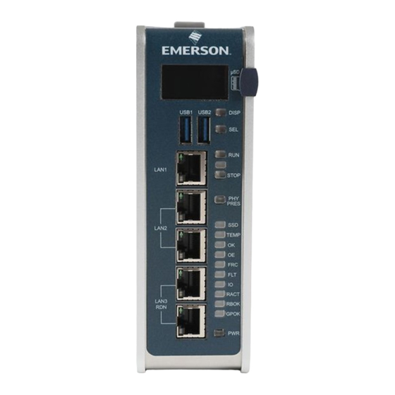
Page 5: Introduction
Introduction The PACSystems™ RX3i CPL410/CPE400 deploys with PACEdge, which is Emerson’s software suite for data analytics and visualization. Front Panel Description Figure 1: Display, Lights, and Connectors on the CPL410/CPE400 Rackless CPU w/PACEdge Quick Start Guide GFK-3053G... -
Page 6: Switches
Switches All user-accessible switches are provided as pushbuttons on the front panel as described below. Pushbutton Function DISP Permits user to navigate menus in the OLED display. Permits user to select the menu item on the OLED display. Activates OLED Menu to select RUN/Enabled or RUN/Disabled Mode for the embedded PLC. -
Page 7: Displays And Indicators (Leds)
Displays and Indicators (LEDs) OLED Display The monochrome organic light-emitting diode (OLED) display is used to display CPL410/CPE400 system menus. It interacts with the DISP pushbutton, which jogs the cursor from one menu item to the next, and with the SEL pushbutton, which activates the currently indicated menu item for further action. -
Page 8: Status Indicators (Leds)
Status Indicators (LEDs) LED State Operating State On Green PLC is in RUN mode. MODE PLC is in STOP mode. Blinking CPU is updating an internal programmable in unison hardware device. On Green TPM Physical Presence (not functional). PRES On Green Activity detected on Solid State Disk. No activity detected on Solid State Disk. - Page 9 LED State Operating State On Green Output scan is enabled. Output scan is disabled. One or more Overrides active in I/O Reference Yellow Table(s). No Overrides active in any I/O Reference Table. PLC is in STOP/Faulted mode: a fatal fault has On Red occurred.
-
Page 10: Bottom Ethernet Indicators (Pacedge Rj45 Built-In Led)
Front Ethernet Indicators (LAN1, LAN2, LAN3 RJ45 Built-in LEDs) LED State Operating State The corresponding link has been established. Green Link Status Blinking Traffic is detected at the corresponding port. (upper) Green No connection established at corresponding port. Link Corresponding data speed is 1 Gbps or 100 Mbps. Green Speed (lower) -
Page 11: Interfaces And Connectors
Interfaces and Connectors USB Ports On the front panel CPL410/CPE400 features 2 USB 3.0 ports, labeled USB1 and USB2. • USB1 is assigned to PACEdge and can be used for storage devices. For other USB devices an appropriate Linux driver will need to be installed. -
Page 12: Pacedge Port
To establish Ethernet communications between the PME programming and configuration software and the CPU, the user will first need to know the target IP address. Use the OLED menu function to check the IP Address. The factory-shipped settings are: CPL410/CPE400 CPL410/CPE400 CPL410/CPE400 LAN1... -
Page 13: Serial Com Port
Serial COM Port Figure 2: Underside Ports & Connections The RJ45 port marked Serial COM is located on the underside of the CPL410/CPE400, as shown in Figure 2. Effective with firmware release 9.40, the CPL410/CPE400 supports the serial port. This port supports Serial IO protocol. -
Page 14: Energy Pack Connector
Energy Pack Connector The CPL410/CPE400 compatible Energy Pack, IC695ACC403, is supplied with a purpose-built cable, IC695CBL003, which installs in the 24 VDC In and Energy Pack Control & Status connectors shown in Figure 2. Use of the Energy Pack is optional. When used, it allows the CPL410/CPE400 to save its current state upon loss of power. -
Page 15: Hardware Installation
As the consignee, it is the user’s responsibility to register a claim with the carrier for damage incurred during shipment. Emerson will fully cooperate with the user, however, should such action be necessary. After unpacking the equipment, record all serial numbers. Serial numbers are required if the user should need to contact Customer Care during the warranty period. -
Page 16: Installation
Installation For instructions on wall mounting instructions, DIN rail mounting instructions, or minimum clearances required, please consult GFK-2222, RX3i CPU Reference Manual. As shipped, the CPL410/CPE400 is intended for mounting on a DIN rail. A panel-mount adaptor is also available. If panel-mounting is required, replace the DIN-rail adaptor with the panel-mount adaptor using the screws supplied with that adaptor. -
Page 17: Connect To Power Supply
Connect to Power Supply Figure 3: 24 VDC Power The 24 VDC power input connector is Input Connector located on the underside of the CPL410/CPE400, as shown in Figure 3. The signal pinouts are also indicated. The mating connector for the CPL410/CPE400 24Vdc power input is the 3- pin Phoenix 1827716 shown in Figure 4. - Page 18 The user-supplied SELV power supply must supply voltage in the range of 18Vdc to 30Vdc. Figure 4: 24 VDC Power Once the power supply cable (or compatible Input Module Connector Energy Pack ACC403) has been attached to the CPL410/CPE400 and the power supply has been turned on, the unit will start booting.
- Page 19 Overvoltage Protection In the CPL410/CPE400, the voltage to the inner loads is clamped to 33 VDC. At 33 VDC, the internal clamping diode starts conducting at 1 mA. Any further increase in the voltage will cause the internal current fuse to blow and/or the clamping diode to break.
-
Page 20: Module Start-Up
Module Start-up Equipment Needed This PACSystems Rackless RX3i CPU. ▪ A compatible SELV 24Vdc, 48W power supply (72W if Energy Pack ▪ attached). (Optionally) A compatible Energy Pack, IC695ACC403, and corresponding ▪ cable. If no Energy Pack is to be attached, use the power supply cable described in ▪... -
Page 21: Basic Start-Up Steps
Basic Start-up Steps For startup and configuration of the CPL410/CPE400, complete the following steps. For full details on CPL410/CPE400 operation, refer to the PACSystems RX3i and CPU Reference Manual, GFK-2222Y or later. 1. Mount the CPL410/CPE400, as described in the Installation section and per the Installation and Maintenance Requirements document, GFK-3004. -
Page 22: Cpl410/Cpe400 Plc Configuration
event the ACC403 is faulty or is not communicating, CPL410/CPE400 commences operation without the Energy Pack. Note: In the event of loss of power, with the ACC403 Energy Pack connected and charged up, the CPL410/CPE400 remains on for 4 seconds to backup user memory into its non-volatile memory. -
Page 23: Profinet Controller Configuration
PROFINET Controller Configuration An Embedded PROFINET Controller may be configured on LAN2. To enable the PROFINET Controller in a CPL410/CPE400 project, select the CPL410/CPE400 target in the PME Navigator (Figure 5) and open the Hardware Configuration. On the Settings tab, change the designated LAN Mode of the selected port to PROFINET. -
Page 24: Redundancy Configuration
Redundancy Configuration It is possible to configure the RX3i PLC part of CPL410/CPE400 as a Hot Standby Redundancy CPU with PROFINET IO. The two ports on LAN3 are used exclusively for this purpose: they provide a high-speed data synchronization link between the two CPUs. Connect the upper LAN3 port of the Primary CPU to the upper LAN3 port of the Secondary CPU and connect the lower LAN3 port of the Primary to the lower LAN3 port of the Secondary. -
Page 25: Pacedge
WebHMI provides HMI/SCADA and productivity tools, which will in turn improve up-time. Note: Customers that have a previous model of the CPL410 without the PACEdge+Connect are able to download and license the software from the MAS Customer Portal free of charge. https://emerson-mas.force.com/communities/ Rackless CPU w/PACEdge Quick Start Guide GFK-3053G... -
Page 26: Pacedge Quick Start
PACEdge Quick Start CPL410/CPE400 units come with pre-installed PACEdge software. Following chapters will describe how to get started with PACEdge. PACEdge Usage Model PACEdge software on CPL410/CPE400 is designed to be used in a headless mode, with the user accessing it remotely via Ethernet using a web browser. Figure 6: Use Case PACEdge User PACs Controller User... - Page 27 Getting Started 1. Connect the Ethernet cable to the Ethernet port on the bottom of the unit, labeled ETH. 2. Setup the User PC Ethernet port IP address to be statically assigned as follows: a. IPv4 Static IP: 192.168.3.10 (or similar in the same subnet) b.
- Page 28 Please click on Advanced and Accept to proceed. Please read and accept the Emerson End User License Agreement (EULA). Once EULA has been accepted the user will be redirected to the Password Services screen.
- Page 29 Figure 7: Password Services Screen (The Left Side will Display the User Level Passwords) Figure 8: Password Services Screen (The Right Side will Display the Portainer and Cockpit/Linux Passwords) Rackless CPU w/PACEdge Quick Start Guide GFK-3053G...
- Page 30 Once the passwords have been changed, click on the Emerson logo in the upper-left corner. The logo is a shortcut to the PACEdge Landing Page, which has further shortcuts to Node-RED, Grafana, Cockpit, Portainer, and other applications. The user can return to the Password Services screen from the PACEdge landing page by clicking Password Management in the Settings drop-down list on the right side.
-
Page 31: Factory Reset
After the Factory Reset has been triggered, a manual power cycle must be ▪ executed. Important: Emerson recommends disconnecting the power to the PLC instead of using the power button. Using the power button may result in the loss of User Memory in RAM. -
Page 32: Additional Information
Note: All PACEdge data, user modifications, updates, database content will be deleted during the factory reset process. Therefore, consider making backups of all databases and changes applied to PACEdge frequently. Additional Information PAC Logic Developer-PLC Getting Started GFK-1918 PACSystems RX3i and RSTi-EP CPU Reference Manual GFK-2222 PACSystems RX3i and RSTi-EP TCP/IP Ethernet Communications User’s Manual GFK-2224... -
Page 33: General Contact Information
All Rights Reserved. We reserve the right to modify or improve the designs or specifications of the products mentioned in this manual at any time without notice. Emerson does not assume responsibility for the selection, use or maintenance of any product.
Need help?
Do you have a question about the PACSystems IC695CPE400 and is the answer not in the manual?
Questions and answers