
Subscribe to Our Youtube Channel
Related Manuals for Emerson PACSystem RX3i


Summary of Contents for Emerson PACSystem RX3i
- Page 1 PACSystem™ RX3i Central Processing Unit IC695CPE305 Quick Start Guide GFK-2934B Sept 2019...
-
Page 2: Table Of Contents
Contents User Features ................. 2 Switches ..................4 Switch Operation ................4 Real-Time Clock Ba ttery ..............5 Ethernet Port ................. 5 Serial Port ..................6 Removable Data S torage Devices (RDSDs) ..........6 Energy Pa ck ........ -
Page 3: User Features
User Features The PACSystems™ RX3i CPE305 can be used to perform real time control of machines, processes, and material handling systems. The CPU communicates with the programmer via the internal Ethernet port or a serial port. It communicates with I/O and Intelligent Option modules over a dual PCI/Serial backplane. - Page 4 Supports most Series 90-30 modules and expansion racks. For supported I/O, ▪ Communications, Motion, and Intelligent modules, refer to the PACSystems RX3i Hardware and Installation Manual, GFK-2314 Supports up to 512 program blocks (Maximum size for a block is 128KB) ▪...
-
Page 5: Switches
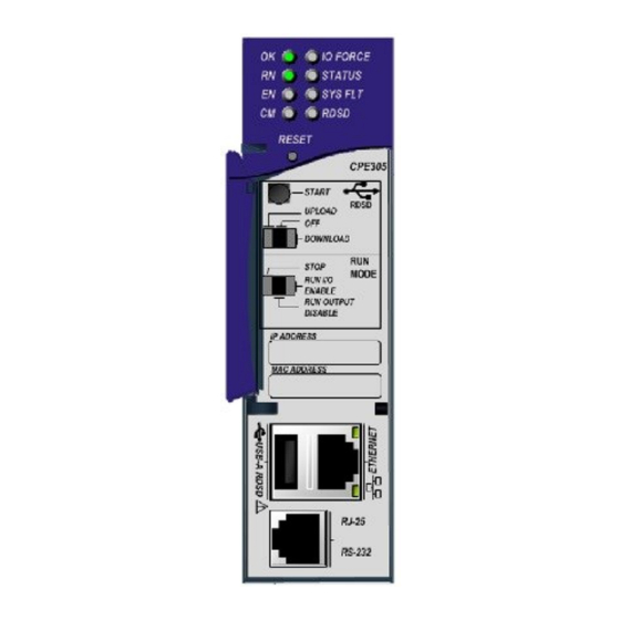
Switches The RDSD and Run Mode switches are located behind the front protective door. The Reset switch is not used. Switch operation is given in the following table. Switch Operation RDSD Switches Function Start pushbutton Pressing this switch initiates RDSD data transfer. (The three-position switch must be set to Upload or Download.) Three-position switch... -
Page 6: Real-Time Clock Battery
Real-Time Clock Battery The CPE305 is shipped with a real time Figure 1: Real-Time Clock clock (RTC) battery (IC690ACC001) Battery installed, with a pull-tab on the battery. The pull tab should be removed before installing the CPE305. There are no diagnostics or indicators to monitor RTC battery status. -
Page 7: Serial Port
Serial Port The CPE305 provides one RS-232 serial interface to external devices. This port can be used for firmware upgrades. The port is electrically isolated. For serial port pin assignments and details on serial communications, refer to the PACSystems RX3i CPU Reference Manual, GFK-2222. The RS-232 port does not supply the 5 VDC power offered by other RX3i and Series 90-30 CPUs. -
Page 8: Energy Pack
Energy Pack The CPE305 preserves user memory using an Energy Pack without the need to periodically replace batteries. The IC695ACC400 Energy Pack powers the CPU long enough for the CPU to write its user memory contents to the CPU’s non-volatile storage during a system power loss. Installation of the Energy Pack is found below. - Page 9 Green, CPU is in boot mode and is waiting blinking in for a firmware update through a unison with serial port. EN — indicates outputs enabled. Green, ON Output scan is enabled. steady Output scan is disabled. CM — indicates activity on the serial communications port. Green, blinking Signal activity on the COM1 port.
- Page 10 Energy Pack near its end of life and should Red, blinking replaced soon. Energy Pack is charged above its Green, ON minimum operating voltage. steady SYS FLT — indicates presence of a fatal fault. No fatal faults. CPU is in Stop/Faulted mode because a fatal fault Red, ON has occurred.
-
Page 11: Hardware Installation
As the consignee, it is your responsibility to register a claim with the carrier for damage incurred during shipment. Emerson Automation Solutions will fully cooperate with you, however, should such action be necessary. After unpacking the RX3i equipment, record all serial numbers. Serial numbers are required if you should need to contact Customer Care during the warranty period. -
Page 12: Installation In Hazardous Areas
installing RX3i rack systems, refer to the PACSystems RX3i System Manual, GFK-2314. If you need technical help, contact Technical Support. For phone numbers and email addresses, see the back cover of this Guide. Installation in Hazardous Areas The following information is for products bearing the UL marking for Hazardous Areas or ATEX marking for explosive atmospheres: Class 1 Division 2 Groups ABCD •... -
Page 13: Atex Zone 2
ATEX Zone 2 This product must be mounted in an enclosure certified in accordance with EN60079-15 for use in Zone 2, Group IIC and rated IP54. The enclosure shall only be able to be opened with the use of a tool. Module Installation For initial startup and configuration of the CPE305, complete the following steps. -
Page 14: Module Initial Startup
threaded holes in the bottom of the backplate and screw them several turns using a #1 Phillips screwdriver. Tighten to 0.7 N-m (6 in-lbs.). 5. Mount the Energy Pack on the left side of the module in slot 0 of the rack (typically a power supply). -
Page 15: Initial Configuration
Initial Configuration 1. Using PAC Machine Edition (PME) software, configure the CPE305 in an RX3i target. Note: If you intend to use the module’s embedded Ethernet interface, you will probably need to assign it a new IP address. To configure the embedded Ethernet interface in Machine Edition, expand the CPU slot to display the Ethernet daughterboard. - Page 16 2. Go online with the target and download the configuration. You can use one of the following methods for the initial connection to the CPE305: a. Using an IC693CBL316 cable, connect to the module’s RJ-25 RS-232 serial port to the programmer computer. The computer must be equipped with an RS-232 serial port with a standard AT-style nine-pin male D-connector.
- Page 17 PACSystems RX3i System Manual GFK-2314 PACSystems RX3i IC695CPE305 CPU Important Product GFK-2714 Information PACSystems RX3i TCP/IP Ethernet Communications User GFK-2224 Manual User manuals, product updates and other information sources are available on the Support website https://www.emerson.com/en-us/support PACSystems™ RX3i Central Processing Unit IC695CPE305 GFK-2934B...
- Page 18 All Rights Reserved. We reserve the right to modify or improve the designs or specifications of the products mentioned in this manual at any time without notice. Emerson does not assume responsibility for the selection, use or maintenance of any product.
Need help?
Do you have a question about the PACSystem RX3i and is the answer not in the manual?
Questions and answers