Table of Contents
Advertisement
Quick Links
Warranty
All products manufactured by ICP DAS are warranted against defective
materials for a period of one year from the date of delivery to the original purchaser.
Warning
ICP DAS assume no liability for damages consequent to the use of this product.
ICP DAS reserves the right to change this manual at any time without notice. The
information furnished by ICP DAS is believed to be accurate and reliable. However,
no responsibility is assumed by ICP DAS for its use, nor for any infringements of
patents or other rights of third parties resulting from its use.
Copyright
Copyright 1999 by ICP DAS. All rights are reserved.
Trademark
The names used for identification only may be registered trademarks of their
respective companies.
User's Manual for DIO Daughter Boards (Ver.2.5, Jan/2004,DPH-000-25)
DB-16R/DB-16P/DB-16P8R/DB-24R/DB-24RD/DB-24PR/DB-24PRD
DB-24C/DB-24OD/DB-24POR/DB-24SSR/DB-24P
Digital I/O
Daughter Board
User's Manual
Advertisement
Table of Contents

Related Manuals for ICP DAS USA DB-16R


Summary of Contents for ICP DAS USA DB-16R
- Page 1 Copyright Copyright 1999 by ICP DAS. All rights are reserved. Trademark The names used for identification only may be registered trademarks of their respective companies. User’s Manual for DIO Daughter Boards (Ver.2.5, Jan/2004,DPH-000-25) DB-16R/DB-16P/DB-16P8R/DB-24R/DB-24RD/DB-24PR/DB-24PRD DB-24C/DB-24OD/DB-24POR/DB-24SSR/DB-24P...
-
Page 2: Table Of Contents
Contents DIO Daughter Board ..................4 1.1. How to select daughter board..................4 1.2. Selection Table ......................5 DB-16R 16 Relay Output Board................8 2.1. Features ........................8 Specifications ......................9 2.2. Layout........................10 2.3. 2.4. Jumper Setting......................10 2.5. Pin Assignment ......................11 DB-16P 16 Opto-Isolated Digital Input Terminal Board ........12... - Page 3 5.3. Layout........................25 5.4. Pin Assignment ......................26 DB-24PR / DB-24PRD ..................28 6.1. Features ........................28 Specifications ......................29 6.2. 6.3. Applications ......................30 6.4. Layout........................30 6.5. Pin Assessment......................31 DB-24C 24-Channel Open-Collector Output Board ........33 7.1. Features ........................33 Applications ......................
- Page 4 10. DB-24SSR 24-Channel Solid State Relay Board..........44 10.1. Features ........................44 Applications ......................45 10.2. 10.3. Specification ......................45 Layout........................46 10.4. Block Diagram ......................47 10.5. 10.6. Wiring Diagram......................47 Pin Assignment ......................48 10.7. DB-24P 24 Photo-Isolated Digital Input Terminal Board ......49 11.1.
-
Page 5: Dio Daughter Board
1. DIO Daughter Board We provide all kind magnetic relay, SSR, open-collector, photo-mos relay and isolated digital input, daughter boards for I/O control applications. 1.1. How to select daughter board You must make sure which digital I/O board you choose and what kind applications you designed. -
Page 6: Selection Table
1.2. Selection Table Output Type Daughter Board Spec. DB-16R DB-24R DB-24RD Type Magnetic Relay Magnetic Relay Magnetic Relay Contact 1c(1 Form C) 1C(1 Form C) 1C(1Form C) Arrangement (Each channel ) Channel number Contact rating 0.5A/120VAC 0.5A/120VAC 0.5A/120VAC 1A/30VDC 1A/30VDC... - Page 7 Spec. DB-24OD DB-24SSR DB-24POR Type Open-darin Solid-state Relay PhotoMos Relay Contact N-MOS 1A (1 Form A) 1A (1 Form A) Arrangement (Each channel ) Channel number Contact rating 250mA 4A / 50-250VAc Expected Life Very Long life 200,000t 200,000t (Rated Load) Maintenance free Coil rate voltage External Power...
- Page 8 Input Type Daughter Board Spec. DB-16P DB-24P DB-24PD Optically Isolated Optically Isolated Optically Isolated Type Channels Input Range 5~24V DC/AC 5~24V DC/AC 5~24V DC/AC Input Impedance 1.2K ohm 1.2K ohm 1.2K ohm connector 20-pin header 50-pin header 50-pin header 37-pin D-sub connector DIN-Rail Mounting No DB-24P/DIN...
-
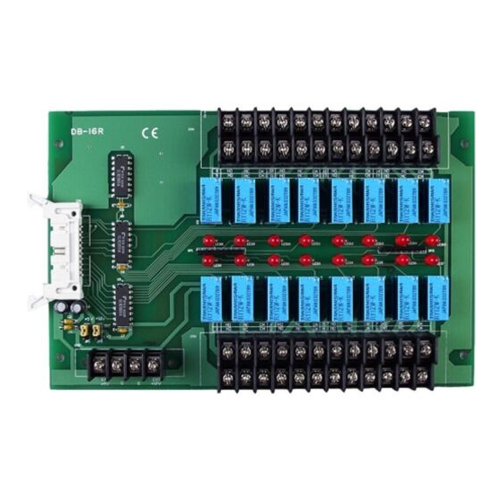
Page 9: Db-16R 16 Relay Output Board
2. DB-16R 16 Relay Output Board The DB-16R, 16 channel Relay Output Board, consists of 16 form c relays for efficient switch of load by programmed control. It is connector and functionally compatible with 785 series board but with industrial type terminal block. The DB-16R can be connected to DIO-64, A-626, A82x DAS board and PCI-series multi-function board or any other compatible DAS board. -
Page 10: Specifications
DB -16R 2.2. Specifications Type : form c Nominal load :……………………….0.5 A/120VAC , 1A /24VDC Max. Switching Power : …………….60VA,24W Max. Switching Voltage : …………..120VAC , 60VDC Max. Switching Current : …………...1A Life Expectancy : ……………………Electrical (20 Millions Times ) Time Value : Operate ……………….6ms Release …….......…….….3ms Control Logic : ………………………Input TTL high (+5V) , relay on... -
Page 11: Layout
INT: Internal Power Source EXT: External Power Source Don’t install too much DB-16R in one PC if the jumper is set in the internal power. Some PC’s power supply is small and used to power PC only. The power supply will be damaged, if install too much DB-16R and using internal power. -
Page 12: Pin Assignment
The CN1 is 20-pin header linked to TTL digital I/O board via 20-pin flat cable. The CN2 is an external power input connector for external power input wiring. The CN3 and CN4 are relay contact screw terminal blocks. DB-16R -CN1 : 20 Pin connector CN2: External Power Input Connector +5V GND GND +12V Note : Don’t wiring to external power input connector if the power... -
Page 13: Db-16P
DB –16P 3. DB-16P 16 Opto-Isolated Digital Input Terminal Board The DB-16P is a 16 channel isolated digital input daughter board for A-82x DAS board or any 812PG, 711 series DAS boards. The optically isolated inputs of the DB-16P consist of a bi-directional LED with a resistor for current sensing. -
Page 14: Specifications
DB –16P 3.2. Specifications I/O connector Electrical Specifications Configuration: optically isolated digital input channels Compatibility: TTL compatible Digital Input Number of channels: 16 Channels, each channel with its own ground reference isolated from other channels Maximum input voltage: 24 VDC or 24 VAC Digital Logic Level: Level Minimum... -
Page 15: Layout
DB –16P 3.4. Layout 3.5. Jumper setting With filter for AC signal Without filter for DC signal If you are using AC signal, You must short the AC FILTER jumper. If you are using DC input signals, the AC FILTER is optional. If the response time of input signals less than 20µs, set the filter off. -
Page 16: Isolated Input
DB –16P Photo-Couple 3.6. Isolated Input The normal input voltage range is 5 to 24 V AC or DC . The normal input range can be changed by choosing suitable resistor to limit the current through the Photo-isolator to about 10 mA(If). The default resistor is 1.2KΩ/1 W. -
Page 17: Pin Assignment
DB –16P 3.7. Pin Assignment CN1 Pin assignment TB1 Pin assignment 17 18 Number Label 0H 0L 1H 1L 2H 2L 3H 3L 4H 4L 5H 5L 6H 6L 7H 7L F.G. F.G TB2 Pin assignment Number 8H 8L 9H 9L 10H 10L 11H 11L 12H 12L 13H 13L 14H 14L 15H 15L +5V +12V Label User’s Manual for DIO Daughter Boards (Ver.2.5, Jan/2004 ) -
Page 18: Db-16P8R
DB –16P8R 4. DB-16P8R The DB-16P8R is a 16-channel isolated/non-isolated input & 8-channel relay output board. The isolated digital input can be used to sense 3.5V to 24V DC signal. The non-isolated digital input are used to sense dry contact. The relay output consists of 16 form C power relays. -
Page 19: Board Layout
DB –16P8R 4.2. Board Layout User’s Manual for DIO Daughter Boards (Ver.2.5, Jan/2004 ) -
Page 20: External Power & Relay Output
DB –16P8R 4.3. External Power & Relay Output Relay Output User’s Manual for DIO Daughter Boards (Ver.2.5, Jan/2004 ) -
Page 21: Digital Input Configuration
DB –16P8R 4.4. Digital Input Configuration JP?? Select Isolated D/I JP?? Select Non-Isolated D/I User’s Manual for DIO Daughter Boards (Ver.2.5, Jan/2004 ) -
Page 22: Leds & Jumper Mapping
DB –16P8R 4.5. LEDs & Jumper Mapping OPTO-22 LEDs Relays / DIs CON5(50-pin) CON6(30-pin) LED0 Relay-0 Pin-47 Pin-37 LED1 Relay-1 Pin-45 Pin-36 LED2 Relay-2 Pin-43 Pin-35 LED3 Relay-3 Pin-41 Pin-34 LED4 Relay-4 Pin-39 Pin-33 LED5 Relay-5 Pin-37 Pin-32 LED6 Relay-6 Pin-35 Pin-31 LED7... -
Page 23: Pin Assignment Of Con5 & 6
DB –16P8R 4.6. Pin Assignment of CON5 & 6 CON6: 37-pin D-Sub connector Pin Number Description Pin Number Description N.C. N.C. N.C. XXXXX This pin is not available User’s Manual for DIO Daughter Boards (Ver.2.5, Jan/2004 ) -
Page 24: Db-24R / Db-24Rd
DB –24R/24RD 5. DB-24R / DB-24RD The DB-24R / DB-24RD, 24 channel Relay Output Board, consists of 24 form c relays for efficient switch of load by programmed control. The DB-24R can be connected to DIO-24, DIO-48, DIO-D96, DIO-144, PIO-D144, PIO-D96 and PIO-D48 and any other OPTO-22 compatible Digital I/O board The relays are energized by apply 5 volt signal to the appropriate relay channel on the 50-pin header or 37-pin D-sub connector (DB-24RD). -
Page 25: Specification
DB –24R/24RD 5.2. Specification Type : form c Nominal load :…………… 0.5 A/120VAC , 1A /24VDC Max. Switching Power : … 60VA,24W Max. Switching Voltage : … 120VAC , 60VDC Max. Switching Current : … 1A Life Expectancy : ………… Electrical (20 Millions Times ) Time Value : Operate ……... -
Page 26: Layout
DB –24R/24RD 5.3. Layout 50-pin Header External power input screw terminal DB-24R DB-24RD 37-pin D-sub connector 50-pin header External power input screw terminal DB-24PR and DB-24R support external power supply only. DB-24R/12V, DB-24RD/12V for DC 12V external power supply DB-24R/12V, DB-24RD/24V for DC 24V external power supply CN3 / CN4 DIO Board DB-24R / DB-24RD... -
Page 27: Pin Assignment
DB –24R/24RD 5.4. Pin Assignment CN6: OPTO-22 50-Pin Header Pin assignment for DB-24R and DB-24RD +5V input CN7 : 37-pin D-sub connector Pin-Assignment for DB-24RD only N.C. N.C. N,C, N.C. CH10 CH11 CH16 CH08 CH12 CH17 CH13 CH18 CH10 CH14 CH19 CH11 CH15... - Page 28 DB –24R/24RD CN 1 /CN 2 : Screwing terminal CH 12 CH 14 CH 16 CH 18 CH 20 CH 22 CH 13 CH 15 CH 17 CH 19 CH 21 CH 23 CN 3 / CN 4 : Screwing terminal CH 0 CH 2 CH 4...
-
Page 29: Db-24Pr / Db-24Prd
DB –24PR/24PRD 6. DB-24PR / DB-24PRD The DB-24PR / DB-24PRD, 24 channel power relay output board, consists of 8 form C & 16 form A electromechanical relays for efficient switching of load by programmed control. The contact of each relay can control a 5A load at 250VAC/30/VDC. -
Page 30: Specifications
DB –24PR/24PRD 6.2. Specifications Form A relays Type : 1 form A (SPST-NO) Rating : Nominal Load …………………..…..5A 250VAC or 30VDC Max. Switching Power…………....90W Max Switching Voltage……………..270VAC,150VDC. Max. Switching Current……………..5A Life expectancy: Mechanical……………………..…..…20 millions operations Time Value: Operate………………………..……….10ms Release…………………………..…….5ms Form C Relays Type : 1 form C ( SPDT ) Rating :... -
Page 31: Applications
DB –24PR/24PRD 6.3. Applications Test Automation Laboratory & Factory Automation On/Off Control 6.4. Layout 50-pin header 20-pin header DB-24PR 37-pin D-sub connector DB-24PRD 50-pin header Form C relay External Form A relay power input Note : DB-24PR, DB-24PRD provides external power input only. The input power has two versions: External Power +12Vdc input for 12V Version External Power +24Vdc input for 24V version... -
Page 32: Pin Assessment
DB –24PR/24PRD 6.5. Pin Assessment CN6: 20-pin header (DB-24PR only) CN5 : 50-pin header ( DB-24PR & DB-24PRD ) +5V input CN6: 37-pin D-sub connector ( DB-24PRD only ) N.C. N.C. CH10 N,C, CH11 CH12 N.C. CH13 CH14 CH16 CH08 CH15 CH17 CH16... - Page 33 DB –24PR/24PRD CN1 : Screw terminal CM NC NO CM NC NO CM NC NO CM NC NO CN2 : Screw terminal CM NC NO CM NC NO CM NC NO CM NC NO CN3 : screw terminal CH23 CH21 CH19 CH17 CH15...
-
Page 34: Db-24C 24-Channel Open-Collector Output Board
DB –24C 7. DB-24C 24-Channel Open-Collector Output Board The DB-24C has 24 channels of optically isolated digital outputs, arranged into four isolated banks. Each digital output offers a darlington transistor and integral suppression diode for inductive load. The board interface to field logic signals, eliminating ground-loop problems and isolating the host computer from damaging voltages. -
Page 35: Applications
DB –24C 7.2. Applications Leds indicate the status of transistor Screw terminals for easy field wiring OPTO-22 Compatible connector. D-sub connector 37-pin connector connects directly to PIO-D144, PIO-D96 and PIO-D24 board or another OPTO-22 board with ADP-37 adapter 7.3. Specification The maximum loading current of each high current output channel: 600mA The maximum loading current of each low current output channel: 100mA Power consumption: DC+5V @ 0.4Amax. -
Page 36: Layout
DB –24C 7.4. Layout Pico fuse 37-pin D-sub connector 130mm 50-pin header 20-pin header 220mm CN1 : External Power: 5~24VDC External Power: 5~24VDC GND GND Exp2 GND GND Exp1 CH5~12 Max. Load :100mA CH1~4 Max. Load :600mA CN2 : External Power: 5~24VDC External Power: 5~24VDC GND GND Exp4... -
Page 37: Block Diagram
DB –24C 7.5. Block Diagram DC+5~24V Pico Fuse External Power Open Collector TTL Signal Output 24 Channel Photo-couple isolated Open Collector Output Wiring DC5V~24V Diagram Max. Current EXP 1 600 A - Load + - Load + - Load + External Power UN2064 Output Channels: 1,2,3,4,13,14,15and 16 are 600mA (Max.) -
Page 38: Db-24Od
DB –24OD 8. DB-24OD 24-Channel Open Drain Output Board The DB-24OD has 24-channel optically isolated digital output. The board is the interface for field logic signals, elimination ground-loop problems and isolating the host computer from damaging voltages. The DB-24OD has a single 37-pin D-sub connector, one 50-pin OPTO-22 compatible male header and a 20-pin male header. -
Page 39: Application
DB –24OD 8.3. Application On/off control Energy management Test Automation Process Control Power EXPWR1 EXPWR2 EXPWR3 Input Voltage 10~24VDC 10~24VDC 10~24VDC Input Current 250mA 250mA 250mA 8.4. Layout 20-pin Header 130mm 50-pin header 220mm 37-pin D-sub connector User’s Manual for DIO Daughter Boards (Ver.2.5, Jan/2004 ) -
Page 40: Pin Assignment
DB –24OD 8.5. Pin Assignment External Power Input Output pin EXPWR1, GND1 D0~D7 EXPWR2, GND2 D8~D15 EXPWR3, GND3 D16~D23 8.6. Block Diagram External Power Open Drain Output Photo-couple isolated Short circuit protect User’s Manual for DIO Daughter Boards (Ver.2.5, Jan/2004 ) -
Page 41: Db-24Por
DB –24POR 9. DB-24POR 24-Channel Photo Output Board The DB-24POR includes 24 normally open, form A, Photo-MOS relays. The board interface to field logic signals, eliminating ground-loop problems and isolating the host computer from damaging voltages. The user can use the DB-24POR to switch load, up to 350VAC and up to 130mA, The relay is energized by applying a 5 voltage signal to the appropriate relay channel on the 50-pin OPTO-22 compatible connector or 37-pin D-sub connector. -
Page 42: Applications
DB –24POR 9.2. Applications ON/OFF Control Energy management IC factory Automation Test Automation 9.3. Specification Photo-MOS Relay Item Spec. Note Turn On Time 0.7mS Typical Turn Off time 0.05mS Typical Output On resistance Typical 23Ω Load Voltage 350VAC Peak AC Continuous load current 130mA Peak AC... -
Page 43: Layout
DB –24POR 9.4. Layout CN3 CN4 CN5 Channel 0~23 Form A Normal Open Common Form A type Photo-MOS Relay User’s Manual for DIO Daughter Boards (Ver.2.5, Jan/2004 ) -
Page 44: Block Diagram
DB –24POR 9.5. Block diagram Photo-MOS Relay 9.6. Wiring Diagram 350VAC@130mA(max.) Load AC/DC Power Measurement Meter AC/DC Signal User’s Manual for DIO Daughter Boards (Ver.2.5, Jan/2004 ) -
Page 45: Db-24Ssr
DB –24SSR 10. DB-24SSR 24-Channel Solid State Relay Board The DB-24SSR includes 24 normally open, or form A, solid-state relays The board interface to filed logic signals, eliminating ground-loop problems and isolating the host computer from damaging voltages. The user can use the DB-24SSR to switch high voltage load, up to 240VAC and up to 4A. -
Page 46: Applications
DB –24SSR 10.2. Applications ON/OFF control Energy management Test Automation Process Control 10.3. Specification Solid State Relay ( AC) Load Voltage 50~250VAC Maxi. Load Current Repetitive Peak OFF Voltage 600V Max. “ON-state “ Voltage Drop 1.5V Surge Current Maxi. “OFF-State” Leakage Current Mini. -
Page 47: Layout
DB –24SSR 10.4. Layout Channel 0~23 Form A Normal Open Common Varistor User’s Manual for DIO Daughter Boards (Ver.2.5, Jan/2004 ) -
Page 48: Block Diagram
DB –24SSR 10.5. Block Diagram 10.6. Wiring Diagram 50~250VAC@4A Load User’s Manual for DIO Daughter Boards (Ver.2.5, Jan/2004 ) -
Page 49: Pin Assignment
DB –24SSR 10.7. Pin Assignment DB-24C / DB-24POR / DB-24SSR CN3 Pin Assignment CN4 Pin Assignment +5V input N.C. N.C. N,C, N.C. CH16 CH08 CH17 CH18 CH10 CH10 CH19 CH11 CH11 CH20 CH12 CH12 CH21 CH13 CH13 CH22 CH14 CH14 CH23 CH15. -
Page 50: Db-24P
DB –24P/24PD 11. DB-24P 24 Photo-Isolated Digital Input Terminal Board The general specification of DB-24P is the same as DB-16P. But DB-24P has one Opto-22 compatible 50-pin connector and can be used for 24 channel photo-isolated digital input . The DB-24PD is almost the same as DB-24P. But DB-24PD has one 37-pin D-sub connector. -
Page 51: Specification
DB –24P/24PD 11.3. Specification I/O connector Electrical Specifications Configuration: optically isolated digital input channels Compatibility: TTL compatible Digital Input Number of channels: 24 Channels each channel with its own ground reference isolated from other channels Maximum input voltage: 24 VDC or 24 VAC Digital Logic Level: Level Minimum... -
Page 52: Layout
DB –24P/24PD 11.4. Layout DB-24P / DB-24PD User’s Manual for DIO Daughter Boards (Ver.2.5, Jan/2004 ) -
Page 53: Jumper Setting
DB –24P/24PD 11.5. Jumper setting With filter for AC signal Without filter for DC signal If you are using AC signal, You must short the AC FILTER jumper. If you are using DC input signals, the AC FILTER is optional. If the response time of input signals less than 20µs, set the filter off. -
Page 54: Isolated Input
DB –24P/24PD 11.6. Isolated Input The normal input voltage range is 5 to 24 V AC or DC . The normal input range can be changed by choosing suitable resistor to limit the current through the Photo-isolator to about 10 mA(If). The default resistor is 1.2KΩ/1 W. - Page 55 DB –24P/24PD TB3 Pin Assignment Number Label Number 10H 10L 11H 11L GND GND Label TB2 Pin Assignment Number 12H 12L 13H 13L 14H 14L 15H 15L 16H 16L 17H 17L 18H Label Number 18L 19H 19L 20H 20L 21H 21L 22H 22L 23H 23L +5V +5V Label User’s Manual for DIO Daughter Boards (Ver.2.5, Jan/2004 )
- Page 56 DB –24P/24PD DB-24P: CN1 OPTO-22 Connector Pin Assignment DB-24PD : D-sub connector Pin Assignment DB-24P: Pin Assignment +5V input N.C. N.C. N,C, N.C. CH16 CH08 CH17 CH18 CH10 CH10 CH19 CH11 CH11 CH20 CH12 CH12 CH21 CH13 CH13 CH22 CH14 CH14 CH23 CH15...
-
Page 57: Configuration
12. Configuration 12.1. Connect to DIO Board DB-16P / DB-16R connect to 20-pin digital input / output connector DB-16P linked to digital input port of multi-function board DB-16R linked to digital output port of multi-function board User’s Manual for DIO Daughter Boards (Ver.2.5, Jan/2004 ) - Page 58 The DB-16P / DB-16R linked to Multi-Function board via ADP-20 extender. CA-2002 User’s Manual for DIO Daughter Boards (Ver.2.5, Jan/2004 )
- Page 59 50-pin OPTO-22 compatible connector directly connected DIO-24 DIO-48 DB-24R / DB-24RD DIO-144 DB-24PR / DB-24PRD PIO-D144 DB-24C / DB-24POR PIO-D96 DB-24SSR PIO-D48 User’s Manual for DIO Daughter Boards (Ver.2.5, Jan/2004 )
- Page 60 Connect to 37-pin D-sub connector PIO-D144 / PIO-D96 / PIO-D48 37-pin D-sub DI/O card DB-24RD DB-24PRD DB-24C / DB-24POR 50-pin header convert to 37-pin D-sub DB-24SSR connector via the ADP-37 DB-24R DIO-24 DIO-48 DB-24RD DIO-144 PIO-D144 PIO-D96 PIO-D48 User’s Manual for DIO Daughter Boards (Ver.2.5, Jan/2004 )
-
Page 61: Din-Rail Mounting
12.2. DIN-Rail Mounting The DB-24P,DB-24R, DB-24PR, DB-24C, DB-24POR, DB-24SSR, DB-16P8R series daughter boards can choose DIN-OPTO22 kit for DIN-Rail mounting. DB-24P/DIN DB-24PD/DIN DB-24R/DIN DB-24RD/DIN DB-24PR/DIN DB-24PRD/DIN DB-24C/DIN DB-24POR/DIN DB-24SSR/DIN DB-16P8R/DIN User’s Manual for DIO Daughter Boards (Ver.2.5, Jan/2004 )
Need help?
Do you have a question about the DB-16R and is the answer not in the manual?
Questions and answers