Table of Contents
Advertisement
Advertisement
Table of Contents

Subscribe to Our Youtube Channel
Related Manuals for HID ENTRYPROX


Summary of Contents for HID ENTRYPROX
- Page 1 NTRY ANUAL 4045-905, Rev. C.4 September 2016 hidglobal.com...
-
Page 2: Revision History
HID Global Corporation. Trademarks HID GLOBAL, HID, the HID logo, and EntryProx are the trademarks or registered trademarks of HID Global Corporation, or its licensors, in the U.S. and other countries. All other trademarks, service marks, and product or service names are trademarks or registered trademarks of their respective owners. -
Page 3: Table Of Contents
EntryProx User Manual, 4045-905, Rev. C.4 Contents Introduction ..........................5 Product Overview ........................6 2.1 Unit Capacity ............................6 2.2 Transactions ............................6 2.3 Pre-Programming the Unit Before Installation ................6 2.4 Specifications ............................7 2.5 Default Settings ............................7 Installation ..........................8 3.1 Assembly Parts ............................ - Page 4 EntryProx User Manual, 4045-905, Rev. C.4 Changing Operating Parameters ..................29 8.1 Changing the Main Relay Time ......................29 8.2 Invalid PIN Lockout ..........................29 8.3 Resetting the Master Cod and System Defaults Only ............... 30 8.4 Erasing Entire Memory/Resetting System Defaults ..............30 8.5 Turning KeyPress Audible Feedback On/Off................
-
Page 5: Introduction
IMPORTANT: READ BEFORE PROGRAMMING THE ENTRYPROX UNIT • Keep a User List – When programming cards and PIN codes into your EntryProx, record each User Location, Card Number, PIN Code and the Name of the User. Use the blank form in Appendix: A: Users Chart for Record Keeping as a photocopy master. -
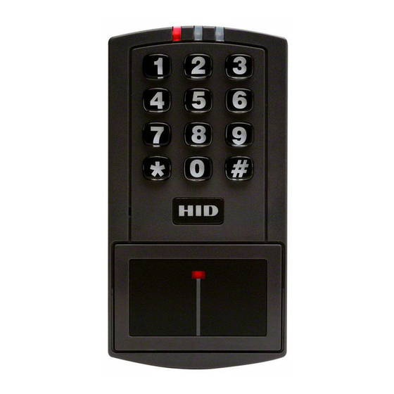
Page 6: Product Overview
PIN code, it unlocks the door or performs some other action that has been programmed for that user. The EntryProx unit is compatible with all HID proximity access cards or key tags encoded with up to 37 bits of data. All programming options are performed using the controller keypad. Manual or batch card/tag programming via the keypad can be completed for 26-bit format only. -
Page 7: Specifications
4000 Hz, defeatable LEDs Bi-Color (red/green) Amber Infrared 2.5 Default Settings The EntryProx unit is shipped with the following default settings. Parameter Default Setting Master Code (User Location 1) 1234* Code must be changed before programming the unit. Main Relay energizes for... -
Page 8: Installation
EntryProx User Manual, 4045-905, Rev. C.4 3 Installation You can install the EntryProx unit by using a standard installation method or a secure installation method. Both installation methods require that you mount the EntryProx unit to a wall or glass surface. -
Page 9: Installed Supplied Parts List
EntryProx User Manual, 4045-905, Rev. C.4 3.2 Installed Supplied Parts List • Appropriate DC power supply (10-15VDC, linear type) • Appropriate separate power supply for door locking unit • Appropriate electrical tools • Recommended remote antenna cable ALPHA 1294C (22AWG) •... -
Page 10: Mounting
4 Mounting If you mount the EntryProx unit to a wall, you can install an electrical junction box to hold the unit and the wires in place. The mounting hole cutouts on the backplate line up with the screw holes on a standard junction box. -
Page 11: Beginning Entryprox Installation
EntryProx User Manual, 4045-905, Rev. C.4 4.2 Beginning EntryProx Installation To mount the EntryProx unit, perform these instructions, referring to the following figures: Remove the hex screw located at the bottom of the EntryProx unit. 2. Disconnect the backplate of the EntryProx unit from the controller keypad. -
Page 12: Controller Keypad Wiring - Standard Installation
CAUTION: For compliance with the UL294 Standard for access control, additional installation requirements must be met. See Section 4.7: Installation and Compliance for UL 294 . To wire the EntryProx unit for a standard installation, refer to perform these steps, referring to the following figure for clarification. -
Page 13: Controller Keypad Wiring - Secure Installation
Note: This is appropriate for exterior doors or medium-to-high risk locations. To wire the EntryProx unit for a secure installation, refer to the following two figures as applicable and perform these instructions. - Page 14 10. Reattach the main circuit board to the controller keypad unit. 11. Insert the blank filler piece into the controller keypad unit. 12. Attach the controller keypad unit to the mounted backplate and secure the EntryProx unit with a hex screw or tamper screw.
-
Page 15: Antenna Housing - Secure Installation
EntryProx User Manual, 4045-905, Rev. C.4 4.5 Antenna Housing – Secure Installation Mount and wire the antenna housing no more than 10 feet away from the controller keypad unit. To mount and wire the antenna housing, refer to the following two figures as applicable and follow these instructions. -
Page 16: Standard Filler Or Secure Filler As Request To Exit Label Installation
EntryProx User Manual, 4045-905, Rev. C.4 4.6 Standard Filler or Secure Filler as Request to Exit Label Installation The filler piece replaces the antenna housing on the controller keypad when you use the high security installation. 4.6.1 Standard Installation To use the filler piece: Insert the filler piece into the opening on the controller keypad. -
Page 17: Secure Installation
EntryProx User Manual, 4045-905, Rev. C.4 4.6.2 Secure Installation To use the filler piece as a Request to Exit switch: Remove the two plastic side tabs on the filler piece. 2. Insert the silicone rubber cushion over the two alignment pins on the switch activator. -
Page 18: Installation And Compliance For Ul 294
EntryProx User Manual, 4045-905, Rev. C.4 4.7 Installation and Compliance for UL 294 The EntryProx Model 4045CGNU0 complies with the UL294 Standard for access control units in a standard, wall-mount installation, when installed to the following specifications: • Electric locking mechanisms may only be connected to the NO contacts of the Main Relay. -
Page 19: Wall Mounting
EntryProx User Manual, 4045-905, Rev. C.4 4.9 Wall Mounting Use an Ademco PR-20451 magnet and reed switch (or equivalent) with foam-backed adhesive tape. 2. Remove the backing sheet from the tape on the magnet and stick the tape to the plastic spacer, which is factory-installed to the back of the Keypad board at location B as shown in the figure in Section 4.9: Wall Mounting. -
Page 20: Wiring
The following figure illustrates the location and description of the four pin connectors on the main circuit board and its use. Connector P5 is not used. Pin Locator Diagram The main relay for the door-locking device is wired to connector P1 on the EntryProx main circuit board. Gate Actuator You can make the wire connections for a gate actuator by connecting the Blue (C) wire and the Green (N/O) wire directly to the input. -
Page 21: Auxiliary Relay
The alarm shunt operation allows you to use the auxiliary relay to bypass a door contact that is monitored by a separate alarm system. If the entry or exit is controlled by the EntryProx unit, an intrusion alarm will not be generated if the door is opened using an access card or PIN number, or by pressing the REX button. -
Page 22: Programming
IMPORTANT: READ BEFORE PROGRAMMING THE ENTRYPROX UNIT • Keep a User List - When programming cards and PIN codes into your EntryProx, record each User Location, Card Number, PIN Code and the Name of the User. Use the blank form in Appendix: A: Users Chart for Record Keeping as a photocopy master. -
Page 23: Led Indication During Program Mode
Press * to clear the error condition, then enter a new code or PIN, or re-enter the command sequence as required. Note: If the unit does not go into program mode, contact your dealer or HID Technical Support. 6.3 Changing the Master Code The EntryProx cannot be programmed before you change the master code. -
Page 24: Pin Code/Card Programming Basics
6.9 Entering User PIN Codes EntryProx user PIN codes consist of a minimum of one digit and a maximum of six digits. Note that a leading “0” is considered a digit, and that the 5-digit code 12345 is different from the six-digit code 012345. -
Page 25: Card/Pin Programming Sequences
Place the EntryProx unit in program mode. Press: 99 # Master Code * 2. On the EntryProx keypad, for Code Quick Enroll Press: user location # PIN * PIN * OR for Card Quick Enroll press: user location # ** <present card>... -
Page 26: Programming Pin Code Only Use
EntryProx User Manual, 4045-905, Rev. C.4 7.3 Programming PIN Code Only Use To program PIN Code operation with Command 50, use the following program sequence: Place the EntryProx unit in program mode. Press: 99 # Master Code * 2. On the EntryProx keypad... -
Page 27: Batch Load Cards By Keypad Entry
Existing data in the User Locations being programmed is overwritten, unless you present a card that is already programmed into the EntryProx, in which case an error is generated. To clear the error, press the * key; then continue presenting cards. -
Page 28: Deleting Users
EntryProx User Manual, 4045-905, Rev. C.4 7.8 Deleting Users To delete a user from the EntryProx, you must know the User Location in which the information is stored. Place the EntryProx unit in program mode. Press: 99 # Master Code * 2. -
Page 29: Changing Operating Parameters
When a preset number of invalid entries is exceeded (set by using Command 32 – option 4, default is 5) the EntryProx will either trigger the Forced Door output, or the keypad will be disabled for a user-configurable time period (select the action, using Command 30, option 19, and then set lockout time by using Command 32 –... -
Page 30: Resetting The Master Cod And System Defaults Only
EntryProx User Manual, 4045-905, Rev. C.4 8.3 Resetting the Master Cod and System Defaults Only Command 40 erases everything from the EntryProx memory except the user list and transaction log and restores the default settings. This is useful if the EntryProx unit has experienced programming problems, or if you wish to delete earlier programming. -
Page 31: Turning Keypress Visual Feedback On/Off
The factory-shipped default setting is ON, but it can be toggled ON and OFF as desired. Place the EntryProx unit in program mode. Press: 99 # Master Code * 2. -
Page 32: Wiegand Mode
EntryProx User Manual, 4045-905, Rev. C.4 9 Wiegand Mode If you program the EntryProx unit to operate in Wiegand mode with a separate access control panel, the following features are not accessible: The EntryProx unit does not control door lock or unlocking operations. -
Page 33: Programming Commands
EntryProx User Manual, 4045-905, Rev. C.4 10 Programming Commands Read the following table before completing programming of your EntryProx unit; it describes various programming commands and how to execute them. As with the previously described commands, you must first press 99 # (Master Code) * to enter programming mode, enter the desired command sequence, and then press * to exit programming mode. - Page 34 EntryProx User Manual, 4045-905, Rev. C.4 Option Press Details Change Wiegand & 32 # parameter # Parameter/Value Miscellaneous parameters value # ** 0, Wiegand pulse width, default=8, 160µs, (1=20µs), range= 1- 255 1, Wiegand interpulse spacing, default=32, 640µs, (1=20µs), range=1-255...
- Page 35 EntryProx User Manual, 4045-905, Rev. C.4 Option Press Details Program user: 52 # user-type # user location # Code OR Card code* repeat code * <present card> Program a group of consecutive 53 # user type # Programs card-only users. Stops at user...
-
Page 36: Led/Sounder Status Indications
EntryProx User Manual, 4045-905, Rev. C.4 11 LED/Sounder Status Indications LED or Sounder Visual/Audible Condition Description Yellow LED Slow blink Unit is in Program mode Rapid blink Verify mode is active (checking that the last two values in sequence match) Steady Program error;... -
Page 37: Appendix: A Users Chart For Record Keeping
EntryProx User Manual, 4045-905, Rev. C.4 Appendix: A Users Chart for Record Keeping Note: Do not write on this page. Use it as a photocopy master and follow the applicable recommendations: Make the number of copies required to record all programmed users. - Page 38 hidglobal.com...
Need help?
Do you have a question about the ENTRYPROX and is the answer not in the manual?
Questions and answers