Table of Contents
Advertisement
Advertisement
Table of Contents

Related Manuals for HID VertX EVO V1000


Summary of Contents for HID VertX EVO V1000
-
Page 1: Installation Guide
VertX EVO V1000 Installation Guide 71000-901, Rev. A.4 July 2016 hidglobal.com... -
Page 2: Revision History
HID Global Corporation. Trademarks HID GLOBAL, HID, the HID logo, and VertX are the trademarks or registered trademarks of HID Global Corporation, or its licensors, in the U.S. and other countries. Revision History... -
Page 3: Table Of Contents
VertX EVO V1000 User Guide, 71000-901, Rev. A.4 Contents Introduction ..........................4 Parts List ..............................4 Product Specifications ........................4 Cable Specifications ..........................5 Overview……………………………………………………………………………………………………………………….6 Connect………………………………………………………………………………………………………………………… 7 What you need before getting started ..................7 V1000 ................................ 7 Mounting Instructions ........................7 Wiring VertX EVO .......................... -
Page 4: Introduction
8 ea. V1000 • 2.2K EOL resistors • Quick Installation Guide • Installation Wiring Diagram Example Note: One or more VertX Interface panels are required when installing a VertX EVO V1000 controller. Product Specifications Description Specification Power Supply 12-24VDC Maximum Current at 12-24VDC per Unit... -
Page 5: Cable Specifications
VertX EVO V1000 User Guide, 71000-901, Rev. A.4 Cable Specifications Cable Type Length Specification 4000 feet (1220 m) to Using Belden 3105A, 22AWG twisted pair, shielded 100Ω RS-485 * host cable, or equivalent. 2-conductor, shielded, using ALPHA 1292C (22AWG) or... -
Page 6: Overview
VertX EVO V1000 User Guide, 71000-901, Rev. A.4 2 Overview The following outlines what is required to install VertX EVO controllers. Page 6 of 25 July 2016... -
Page 7: Connect
VertX EVO V1000 User Guide, 71000-901, Rev. A.4 3 Connect What you need before getting started Prior to starting the installation, completely read this guide. See Section Appendix C: Configuration Checklist - Static, and gather the information before proceeding with these instructions. -
Page 8: Wiring Vertx Evo
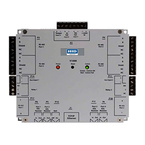
VertX EVO V1000 User Guide, 71000-901, Rev. A.4 3.4 Wiring VertX EVO WARNING: VertX EVO V1000 is a NON-PoE device. DO NOT connect J1 (Ethernet port) to a PoE capable port. This applies to both direct PoE Power Sourcing Equipment (Endspan PSE) and PoE injector (Midspan PSE) equipment. - Page 9 VertX EVO V1000 User Guide, 71000-901, Rev. A.4 3. RS-485 Connections: The V1000 has two RS-485 connectors and uses the 10-pin connector on P3 and P4. Each RS-485 bus can support a maximum of 16 V100-Series panels using one or two ports.
- Page 10 VertX EVO V1000 User Guide, 71000-901, Rev. A.4 4. Output Connections (VertX EVO V1000): All Output connections are used for general purpose controls. The following table shows where the various outputs are located. Pin numbers shown use the convention “NO/C/NC”.
- Page 11 VertX EVO V1000 User Guide, 71000-901, Rev. A.4 They can be configured for supervisory resistors of 1K – 6K Ohm. The setup of supervised inputs should be done during configuration of the VertX EVO devices through the host. Example: Input 1, V1000 is: P14 Pin1 is + (plus) and Pin 2 is – (minus).
-
Page 12: Contact
VertX EVO V1000 User Guide, 71000-901, Rev. A.4 4 Contact Contact the VertX controller through the following methods. Discovery Client (DHCP or Static TCP/IP Configurations Only) Virtual Port 4.1 Discovery GUI (for DHCP networks) The Discovery Client provides a technician with a method of locating all of the VertX controllers that are connected to a network. -
Page 13: Configure
VertX EVO V1000 User Guide, 71000-901, Rev. A.4 5 Configure This section describes the communications configuration that enables the controller to communicate with the host software. There are two methods of communication possible on a V1000 controller: Dynamic Host Configuration Protocol (DHCP) TCP/IP Addressing ... -
Page 14: Confirmation
VertX EVO V1000 User Guide, 71000-901, Rev. A.4 Extended ASCII such as £ (pound) and € (euro) are NOT supported as they lie outside of the original ASCII range. Once configuration changes have been made, click Submit, and the Confirmation window displays. -
Page 15: Communicate
VertX EVO V1000 User Guide, 71000-901, Rev. A.4 6 Communicate Now that the controller is connected, contacted and configured, communicate with the controller using the host. Basic setup is now complete! Additional troubleshooting tools are available on the System Status and Supplemental Configuration windows. -
Page 16: Appendix: A Troubleshooting
VertX EVO V1000 User Guide, 71000-901, Rev. A.4 Appendix: A Troubleshooting A.1 System Status System Status provides a technician with a method of validating the VertX installation, field wiring and installed devices. Perform the System Status at any time after the VertX controller has been installed and power is available. -
Page 17: System Time
VertX EVO V1000 User Guide, 71000-901, Rev. A.4 A.4 System Time System Time provides the ability to view and set the date, time, and time zone values on the controller. Upon initialization, Date, Time, Time Zone and TZ fields will be populated with the current system settings. -
Page 18: Network Defaults Jumper
VertX EVO V1000 User Guide, 71000-901, Rev. A.4 A.7 Network Defaults Jumper The Network Defaults Jumper requires that someone with physical access to the V1000, place a jumper over the Debug port while the controller is rebooting, as detailed below. The controller reconfigures its network settings to the factory defaults when the jumper is on the Debug port during a reboot. -
Page 19: Firewall
VertX EVO V1000 User Guide, 71000-901, Rev. A.4 Firewall If the VertX controller is being installed where it communicates through a firewall, then the firewall may need to be configured to allow TCP data transfer on the specified port(s). Before starting, ensure that any pop-up blocker software is disabled on the computer. -
Page 20: Appendix: B Regulatory
VertX EVO V1000 User Guide, 71000-901, Rev. A.4 Appendix: B Regulatory All National and local Electrical codes apply. This equipment is intended to be powered from a limited power source output of a previously certified power supply. Changes or modifications not expressly approved by the party responsible for compliance ... -
Page 21: Appendix: C Configuration Checklist - Static
VertX EVO V1000 User Guide, 71000-901, Rev. A.4 Appendix: C Configuration Checklist - Static Ensure that the Configuration Checklist contents are provided prior to installing a VertX controller with Static TCP/IP. Note: Advanced setting requirements are shown in gray. Contact... -
Page 22: Appendix: D Vertx Installation Worksheet
VertX EVO V1000 User Guide, 71000-901, Rev. A.4 Appendix: D VertX Installation Worksheet This installation worksheet is provided for you to have a historical record of your system settings. Complete each appropriate field, and keep this worksheet in a safe location. - Page 23 VertX EVO V1000 User Guide, 71000-901, Rev. A.4 V100 Series Information: Interface Address: 0-31 Interface Type: V100, V200, V300 Tamper: AC Fail: BATT Fail: V100 Door / Reader Interface Reader 1: Reader 2: Door Switch 1: REX 1: Door Switch 2:...
- Page 25 hidglobal.com...
Need help?
Do you have a question about the VertX EVO V1000 and is the answer not in the manual?
Questions and answers