
Related Manuals for RMG EC 24


Summary of Contents for RMG EC 24
- Page 1 Volume Corrector EC 24 and Temperature Corrector EC 21 OPERATING INSTRUCTIONS Serving the Gas Industry Worldwide by Honeywell STATUS FEBRUARY 2015...
- Page 2 (and those of other devices) from our website www.rmg.com. RMG Messtechnik GmbH Otto-Hahn-Str. 5 Phone numbers: 35510 Butzbach (Germany) Switchboard: +49 (0)6033 897-0 Fax: +49 (0)6033 897-130 Customer Service: +49 (0)6033 897-127 E-mail: Messtechnik@Honeywell.com Spare Parts: +49 (0)6033 897-173 ........................................... Manual EC 24 · EN05 · 2015-02...
-
Page 3: Table Of Contents
Front panel and keyboard of the EC 24 ............. 13 Display ......................... 14 Programming ....................... 15 Parameters and modes of the EC 21 / EC 24 ............ 18 Coordinate system ....................20 Description of individual columns ..............21 Column structure ......................21 Totalizers ........................ - Page 4 A Equations used with the EC 21 temperature corrector and the EC 24 volume corrector ................. 29 B Block diagram for the EC 21 / EC 24 ............31 C Specifications ....................32 D Examples of connection (EC 21 and EC 24) ..........38 E Instructions for the measuring element of the turbine meter ....
-
Page 5: Introduction
EC 24 volume corrector (correction is performed using measured pressure and temperature values) can be used as a unit together with electronic turbine meters from RMG or separately with any mechanical turbine or rotary displacement meters. -
Page 6: The Coordinate System
In this way, the program and the operating parameters will not be lost and also the meter readings will be retained. A reset is made on the EC 21 / 24 by switching off not only the battery but also a possibly available external power supply..........................................Manual EC 24 · EN05 · 2015-02... -
Page 7: Booting
As soon as the addresses are counted up in the display, you can release the "P" key. The booting procedure has finished, if the totalizer is displayed (now set to 0). Now transfer all device parameters back to the EC 21 / EC 24 or enter the values from the calibration certificate. -
Page 8: Operating Modes
In the case of an external power supply (current transmitter which serves as a power supply and 4 to 20 mA current output at the same time), the EC 21 / EC 24 is completely supplied via a current loop. For this purpose, a power supply unit is required which is to be connected to this output. -
Page 9: Safety Instructions
As to the danger of explosion, please note the following in particular: Only the explosion-protected design of the EC 21 / EC 24 may be used in areas subject to explosion hazards. Connect the pulse outputs of these devices only to intrinsically safe circuits. -
Page 10: Operating Instructions For The Installer
Otto – Hahn – Straße 5 D-35510 Butzbach Application: The device EC 21*/EC 24* is equipment for hazardous area. Assembly/disassembly: When assembling it is to be made sure that the degree of protection of the case is kept. A direct exposure to sun must be avoided. - Page 11 Maintenance: The battery changes may only take place in a safe area. Repairs at this device may be carried out by RMG Messtechnik only. Safety instructions: The manual must be accessible to all persons, who are authorized with the operation of the device.
-
Page 12: Installation
As soon as input X5 terminals 1 / 2 has been short-circuited through an external contact, interruption or resetting is performed. For this purpose, set jumpers at the positions identified with X_S2 to the “reed contact” function..........................................Manual EC 24 · EN05 · 2015-02... - Page 13 In the case of the EC 21 / EC 24, terminal X22 (on TERZ94trm current module which is plugged in the main card) is used as current-loop connection to supply the device and as output current (4- 20 mA).
- Page 14 Use 4-core shielded cables which are twisted together in pairs (type LIYCY) for the data lines (RS 485). The shielding must always be connected to earth on both sides. In the case of the EC 21 / EC 24 , you must proceed as described under “Cable glands”.
- Page 15 Connecting piece Permissible temperature ranges For the standard design, the following fluid temperature and ambient temperature ranges are permitted: Fluid temperature range: -20°C to +60°C Ambient temperature range: -20°C to +60°C or 40°C ........................................... Manual EC 24 · EN05 · 2015-02...
-
Page 16: Installing The Remote Totalizer
In addition, check the plug-in jumpers XS1 / XS2 and XTERZ90 on the board (see inputs and outputs in the annex). Make your settings of XS1 and XS2 as follows: jumpers 3-4..........................................Manual EC 24 · EN05 · 2015-02... -
Page 17: Operation
If the EC 21 / EC 24 is operated together with the measuring element of an electronic turbine meter, the EC 21 / EC 24 contains the totalizing unit of the meter and the data plate of the meter is located on the left side of the front panel. -
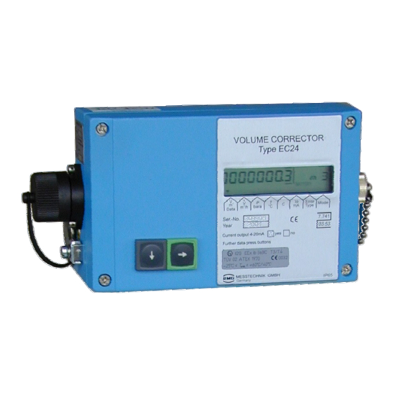
Page 18: Display
EC 21 / EC 24 will return to displaying the main totalizer. If the display of the EC 21 / EC 24 does not show anything, the device is in energy-saving mode. In this mode, the display is completely switched off. However, incoming pulses are processed and the outputs are set. -
Page 19: Programming
Programming Via the programming keys For programming the EC 21 / EC 24, there are four buttons on the rear side of the board. The official parameters are protected by a calibration switch and a password. Via the programming module Instead of using to the programming keys, you can program the device using the programming module. - Page 20 Short-term view of the coordinate (e.g. A01) In programming mode: Go to the right by one decimal place (if the last decimal has been reached: Quit programming mode)..........................................Manual EC 24 · EN05 · 2015-02...
- Page 21 However, there are many parameters which influence the formation of these measured values. These parameters are described in the following section. Display values include the flow rate, version number, year of construction, serial number, value of the current output in mA, for example..........................................Manual EC 24 · EN05 · 2015-02...
-
Page 22: Parameters And Modes Of The Ec 21 / Ec 24
OPERATION ........................................... Parameters and modes of the EC 21 / EC 24 The following sections describe the meaning of the individual parameters. Meter factor (pulse value) With the meter factor (pulse value), the relevant flow rate at measurement conditions is calculated from the signal frequency of the sensor element in the electronic totalizing unit: ... - Page 23 The output pulse value indicates how many LF output pulses correspond to one cubic metre. The output pulse value can be entered in coordinate A 05 from 0.01 to 100 as required..........................................Manual EC 24 · EN05 · 2015-02...
-
Page 24: Coordinate System
T min Error bit string T max Wake-up pulse Ser. no. meter Code number Meter size Beginning of gas day Battery change EcMode2 Charge no. K factor formula Change of code number ........................................... Manual EC 24 · EN05 · 2015-02... -
Page 25: Description Of Individual Columns
The calibration switch is realized by a screw on the left (EC 24) or right (EC 21) side of the device (see fig. on page 10). For opening the calibration switch just unscrew the screw by some turns until the text “Input”... -
Page 26: Totalizers
Binary value at 0.5 V Binary value at 4.5 V Constant, pressure transmitter base calibration Constant, pressure transmitter base calibration bara Constant, pressure transmitter base calibration Correction value, pressure transmitter (factor) Correction value, pressure transmitter (offset) ........................................... Manual EC 24 · EN05 · 2015-02... -
Page 27: Temperature
Coordinate / Coding Description of the coordinate Unit Special feature Line Current out I< Value at 4 mA I> Value at 20 mA I-def Current default Current rise Current offset Current damping ........................................... Manual EC 24 · EN05 · 2015-02... -
Page 28: Error / Id
10=GERG, 11=AGA-NX-19, 12=AGA-8 fixed value Input for change of the code number TerzMode, EcMode and EcMode2 are 8-digit strings where each digit stands for one mode. These modes are listed in the following tables..........................................Manual EC 24 · EN05 · 2015-02... -
Page 29: Operating Modes
OPERATION ........................................... Operating modes ........................................... Manual EC 24 · EN05 · 2015-02... - Page 30 OPERATION ..................................................................................Manual EC 24 · EN05 · 2015-02...
-
Page 31: Error Messages
Too many output pulses in buffer (>500) 0x4000 Sensor defect (check hardware) 0x8000 Sensor defect (check hardware) In the column “Hexadecimal” the error bit strings displayed in coordinate Z 09 are listed..........................................Manual EC 24 · EN05 · 2015-02... -
Page 32: Changing The Batteries (Ec 24)
Changing the batteries (EC 24) The two batteries of the EC 24 can easily be changed without opening the corrector. On the left side of the casing, there is a round slotted cover which can be screwed out. Behind this cover, there is the battery holder. -
Page 33: Annexes
Temperature at measurement conditions in Kelvin Temperature at base conditions (= 273.15 K) K coefficient Compressibility factor at measurement conditions Compressibility factor at base conditions Z and Z are calculated in compliance with GERG-88 as per G9..........................................Manual EC 24 · EN05 · 2015-02... - Page 34 If these transmitters are used, the pressure at base conditions must also be indicated in the appropriate unit. Both the pressure at measurement conditions and the pressure at base conditions will then be converted automatically for the relevant equations..........................................Manual EC 24 · EN05 · 2015-02...
-
Page 35: B Block Diagram For The Ec 21 / Ec 24
ANNEXES ........................................... Block diagram for the EC 21 / EC 24 Current Signal Serial output output interface Pulse Analog Analog input input input ........................................... Manual EC 24 · EN05 · 2015-02... -
Page 36: C Specifications
24 V supply via current-loop connection by means of an intrinsically safe power supply unit, e.g. KFD2-STC3-Ex1 (Ex) plus battery pack. Pulse input Wiegand Current output Only possible via the current-loop connection. Standby battery Only in conjunction with the current-loop connection..........................................Manual EC 24 · EN05 · 2015-02... - Page 37 Jumpers: X_S2 / 3-5 and 4-6 Jumpers: X_TERZ90 / 3-4 Reed contact Jumpers X_S2 / 1-3 and 2-4 1) Attention: In case of use of an external pressure transmitter the maximum cable length reduces to 3m! ........................................... Manual EC 24 · EN05 · 2015-02...
- Page 38 Measuring range: -20°C to 60°C Resolution: ± 0.2 °C Pressure transmitter For Ex connected loads, see the approval certificate. Signal: Voltage: 0.5 V to 4.5 V Resolution: 16 bits Terminals: Plug X16_0 ........................................... Manual EC 24 · EN05 · 2015-02...
- Page 39 125 ms ± 10% (F : 4 Hz) Pulse 250 ms ± 10% (F : 2 Hz) Non-Ex 2.0 V 2.0 V 28 V 30 V 60 mA 400 mA External inductance External capacitance 25 μF ........................................... Manual EC 24 · EN05 · 2015-02...
- Page 40 428 mA 900 mW Inner capacitance: 1.32 μF Inner self-inductance: 600 μH External capacitance: 23.7 μF External inductance: Note: If the RS-485 interface is used, the device is supplied via the data interface..........................................Manual EC 24 · EN05 · 2015-02...
- Page 41 770 mW 2.2 nF 110 μH Supply Battery supply 3.6 V lithium cell; inside the device (battery pack) External 24 V supply 24 V DC; external; via current-loop connection plus battery pack ........................................... Manual EC 24 · EN05 · 2015-02...
-
Page 42: D Examples Of Connection (Ec 21 And Ec 24)
ANNEXES ........................................... Examples of connection (EC 21 and EC 24) Battery-powered device Hazardous area Safe area 24 V/DC Isolating device Connector, Type: Datcom-K3 Binder Series 423 RS 485 LIYCY 2x2x0.5 mm blue Pin assignment (692): Isolating amplifiers 1 = LF -... - Page 43 LIYCY 3x2x0.75 mm blue Connector, Supply unit Binder Series 713 e.g. KFD2-STC4-Ex1 (24 V/DC) Current output LIYCY 2x0.75 mm blue (brown) (white) * If 2-channel isolating amplifiers are used, the two inputs must be separated! ........................................... Manual EC 24 · EN05 · 2015-02...
-
Page 44: E Instructions For The Measuring Element Of The Turbine Meter
Oerstit 500 Lubricator (with TERZ 94 from DN 200) Radial ball bearing Nirosta steel Turbine wheel Delrin / aluminium Flow straightener Hostaform O-ring Sensor sleeve with sensor Nirosta steel O-ring 8x2.5 83FKM592 ........................................... Manual EC 24 · EN05 · 2015-02... - Page 45 Propane Nitrogen Butane Hydrogen Special designs (PTFE lining, special lubrication, special material, etc.) can be used for aggressive and humid gases, such as Ethylene Digester gas Biogas Sulphur dioxide Acid gas etc..........................................Manual EC 24 · EN05 · 2015-02...
- Page 46 The gas flow must be free of shocks and pulsations as well as free of foreign particles, dust and liquids. Any components affecting the gas flow must absolutely be avoided directly upstream of the TERZ 94 or TRZ 03-TE turbine meter..........................................Manual EC 24 · EN05 · 2015-02...
- Page 47 Now check the settings of the pulse width, decade scalers, etc. In the case of models with a current output: Also check the settings of the current output. NOTE: All parameters can only be changed if the device has been opened..........................................Manual EC 24 · EN05 · 2015-02...
-
Page 48: F Dimensions
Ø 6 x 1 TERZ meter (flange-design) *Standard installation Flow direction from right to left display pipe no. 2 Ø 6 x 1 Dimensions MESSTECHNIK GMBH volumeter/PT-corrector 058147.4 Drwg. no. 35510 Butzbach type EVC 24 ........................................... Manual EC 24 · EN05 · 2015-02...
Need help?
Do you have a question about the EC 24 and is the answer not in the manual?
Questions and answers
Hello, after changing the battery, the measurement stopped incrementing, there are numbers but all fixed
The measurement on the RMG EC 24 may not be incrementing after changing the battery because of error conditions. According to the manual, error messages numbered 1 to 8 are fault messages that cause the main totalizers to stop. Possible causes include:
1. EEPROM Parameter Errors (0x0001, 0x0002) – If EEPROM parameters are incorrect or cannot be written, measurement functions may be affected.
2. Sensor Failures (0x0010) – If a sensor failure occurs, the system may not register new measurements.
3. Analog-Digital Converter Issues (0x0004, 0x0008) – If the temperature or pressure measurement ADC fails, the device may not update readings.
To resolve this, check for error messages on the display and troubleshoot based on the error codes.
This answer is automatically generated