Table of Contents
Advertisement
Quick Links
INSTALLER: Leave this manual with the appliance.
CONSUMER: Retain this manual for future reference.
These instructions are supplementary to the Installation and
Operating Instructions supplied with the replace and should be
kept together. Refer to the Installation and Operating Instructions for
proper gas supply, safety requirements and operating instructions
Visit www. townandcountryfireplaces.net for the most recent version of this manual
020317-16
TC36
COUNTRY HOME
BURNER KIT
INSTRUCTIONS
(NATURAL GAS ONLY)
PART# TC36.NG02DN
For TC36 & TC36 Arch
Series D Fireplaces
TC36_NG02DN
5056.42702D
Advertisement
Table of Contents

Related Manuals for Town & Country Fireplaces TC36.NG02DN


Summary of Contents for Town & Country Fireplaces TC36.NG02DN
- Page 1 TC36 COUNTRY HOME BURNER KIT INSTRUCTIONS (NATURAL GAS ONLY) PART# TC36.NG02DN For TC36 & TC36 Arch Series D Fireplaces Visit www. townandcountryfireplaces.net for the most recent version of this manual 020317-16 TC36_NG02DN...
-
Page 2: Contents Of Package
Contents of Package Air De ector Ember Material 7 Pcs Log Set Burner Assembly Hardware Package Log Grate Figure 1: TC36 and TC36 Arch Country home burner kit contents. Burner/Grate Installation Screws Figure 2: Firebox base. 1. Place the keyhole slots of the burner (Figure 3) over the two screws located on the rebox oor (Figure 2). - Page 3 Figure 3: Burner assembly over top of right side screw. Figure 4: Burner assembly pushed back against right side screw. 2. Slide the burner back to engage the screws in the small part of the keyhole slot and tighten screws (Figure 4). 3.
- Page 4 Interface module Figure 6: Gas and pilot supply tubes. 4. Attach the pilot and gas supply tubes to the bulk head tting and tighten (Figure 6). Ensure the connections are gas tight. Interface module Ignition and sensor wires Bulkhead plate Figure 7: Ignition and sensor wires routing.
- Page 5 Flame sensor wire (white) Ignition wire (red) Interface module Figure 8: Interface module. 6. Attach the ignition and sensor wires to the Interface module as shown in Figure 8. 7. Reinstall the valve control center access panel (See Figure 5 on page 3). A panel set must now be installed before the before the log grate can be installed.
- Page 6 Figure 9: Securing log grate to the oor. 8. With a panel set installed, position the slots of the log grate securing brackets over the holes in the oor shield and secure with the two screws (Figure 9). 9. Attach rear de ector to rear of grate using the two screws provided (Figure 10). Air de ector securing screws Figure 10: Rear air de ector.
-
Page 7: Ember Material Placement
Ember Material Placement Glowing ember material Figure 11: Glowing ember placement. A large bag of ember material is shipped with the replace and needs to be installed to ensure opti- mum performance and ame appearance. Pull apart the material into ember size pieces (approximately 1” squares) and gently place them into the burner pan. -
Page 8: Log Placement
Log Placement Gas plumbing and vent connections should be completed before proceeding. The logs are fragile, and should be handled with care. Unpack and inspect log set. There should be a total of seven logs. Position the logs as indicated by the following pictures. The three main logs have holes and / or pins. Engage each pin in the corresponding holes. - Page 9 Figure 14: 3rd log placement. Figure 15: 4th log placement. TC36_NG02DN 020317-16 5056.42702D...
- Page 10 Figure 16: 5th log placement. Figure 17: 6th log placement. TC36_NG02DN 020317-16 5056.42702D...
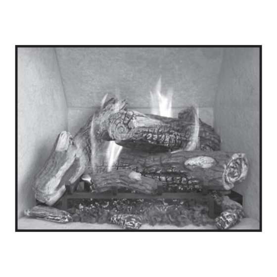
- Page 11 Figure 18: 7th log placement. Figure 19: Completed log placement. TC36_NG02DN 020317-16 5056.42702D...
-
Page 12: Gas Pressure Check
Gas Pressure Check Note: To test the gas pressure, turn off the gas supply before removing the blanking plug from the supply pressure test port or manifold pressure test port. Verify gas pressures with the fireplace lit and on the highest setting. 1. -
Page 13: Burner Flame Adjustment
Burner Flame Adjustment The air shutter on the burner tube controls the primary combustion air to the gas burner and is pre- set at the factory for natural gas fuel. Some adjustment may be necessary to obtain desired ame and to eliminate carbon deposits. Evaluate ame appearance after the replace has reached operat- ing temperature. -
Page 14: Replacement Parts
ITEM DESCRIPTION PART NO. ITEM DESCRIPTION PART NO. #1 COUNTRY HOME BURNER KIT ..TC36.NG02DN #4 PILOT ASSEMBLY, CONVERTIBLE ..TCRP.5005025 #2 COUNTRY HOME LOG SET ....5098.746108 #5 MAIN SUPPLY TUBE........5019.223 #3 ORIFICE, NATURAL GAS ......5022.135 #6 PILOT TUBE ..........5019.225... - Page 15 TC36_NG02DN 020317-16 5056.42702D...
- Page 16 © 2017 Copyright Paci c Energy Fireplace Products LTD Reproduction, adaptation, or translation without prior written permission is prohibited, except as allowed under the copyright laws. For technical support, please contact your retailer Web site: www.townandcountry replaces.net 2975 Allenby Rd., Duncan, BC V9L 6V8 Printed in Canada...
Need help?
Do you have a question about the TC36.NG02DN and is the answer not in the manual?
Questions and answers