Deif AGC 100 Installation Instructions Manual
Genset controller
Hide thumbs
Also See for AGC 100:
- Operator's manual (14 pages) ,
- Designers reference handbook (152 pages)
Table of Contents
Advertisement
Quick Links
INSTALLATION INSTRUCTIONS
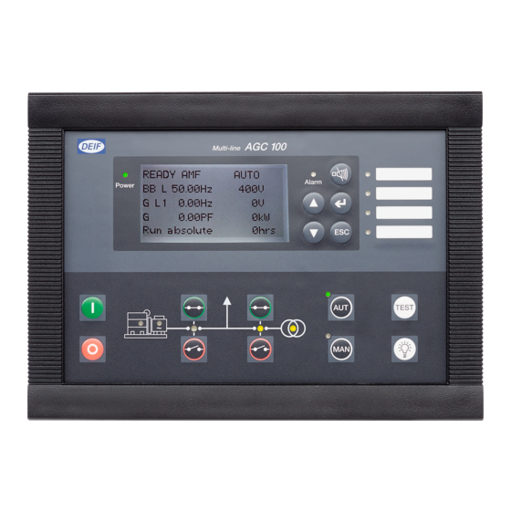
Genset Controller, AGC 100
● Mounting
● Terminal overview
● Wiring
● Communication wiring
● Unit dimensions and cutout
DEIF A/S · Frisenborgvej 33 · DK-7800 Skive · Tel.: +45 9614 9614 · Fax: +45 9614 9615 · info@deif.com · www.deif.com
Document no.: 4189340752C
SW version: 4.0x.x
Advertisement
Table of Contents

Related Manuals for Deif AGC 100


Summary of Contents for Deif AGC 100
- Page 1 ● Unit dimensions and cutout DEIF A/S · Frisenborgvej 33 · DK-7800 Skive · Tel.: +45 9614 9614 · Fax: +45 9614 9615 · info@deif.com · www.deif.com isenborgvej 33 · DK-7800 Skive · Tel.: +45 9614 9614 · Fax: +45 9614 9615 · info@deif.com · www.deif.com Document no.: 4189340752C...
-
Page 2: Table Of Contents
AGC 100 installation instructions 4189340752 UK 1. General information 1.1. Warnings, legal information and safety....................3 1.1.1. Warnings and notes ........................3 1.1.2. Legal information and disclaimer ....................3 1.1.3. Safety issues ..........................3 1.1.4. Electrostatic discharge awareness ....................3 1.1.5. Factory settings ..........................3 1.1.6. UL applications..........................4 1.2. -
Page 3: General Information
1.1.2 Legal information and disclaimer DEIF takes no responsibility for installation or operation of the generator set. If there is any doubt about how to install or operate the engine/generator controlled by the Multi-line 2 unit, the company responsible for the installation or the operation of the set must be contacted. -
Page 4: Ul Applications
AGC 100 installation instructions General information 4189340752 UK 1.1.6 UL applications These flat surface panel-mounted controllers are intended to be used in Listed Generator Assemblies, where the suitability of the combination has been determined by Underwriters Laboratories. 1.2 About the installation instructions 1.2.1 General purpose... -
Page 5: Mounting
AGC 100 installation instructions Mounting 4189340752 UK 2. Mounting 2.1 AGC 100 mounting The unit is designed for flush mounting by means of eight fixing clamps (IP52), which are included at delivery. To have IP65, the unit must be ordered with option L (12 fixing clamps and a gasket). -
Page 6: Tightening Torques
AGC 100 installation instructions Mounting 4189340752 UK 2.1.2 Tightening torques Unit panel door mounting: 0.3 Nm, 2.7 lb-in (see diagram in "Unit dimensions and panel cutout") Plug connections (terminals): 0.5 Nm, 4.4 lb-in AOP-1 and AOP-2 (see diagram below) Panel door mounting: 0.7 Nm, 6.2 lb-in... -
Page 7: Terminals
AGC 100 installation instructions Terminals 4189340752 UK 3. Terminals 3.1 Terminal overview and description Unit rear view 10 11 12 13 14 15 16 19 20 21 23 24 25 26 27 Power Multi-functional Status supply Binary inputs RPM inputs... - Page 8 AGC 100 installation instructions Terminals 4189340752 UK Terminal Technical data Description Power supply + 6 to 36 V DC (UL/cUL Listed: 7.5 to 32.7 V DC) Power supply – Status out/configurable See note*. Contact ratings 1 A 24 V DC/V AC Resistive...
- Page 9 AGC 100 installation instructions Terminals 4189340752 UK Terminal Technical data Description 3-phase generator voltage input Gen. voltage, L1 Generator voltage and frequency Gen. neutral Not used, must not be connec- Gen. voltage, L2 Not used, must not be connec- Gen. voltage, L3 3-phase generator current input Gen.
- Page 10 AGC 100 installation instructions Terminals 4189340752 UK * The status relay is the uP watchdog output. This relay is normally energised, and the switch is closed after power-up. If the uP fails or the power is lost, the relay will de-energise and the switch will open. If the unit fails to start up at power-up, then the relay switch will remain open.
-
Page 11: Wiring
AGC 100 installation instructions Wiring 4189340752 UK 4. Wiring 4.1 Wiring diagram Controller Charging alternator Running 1N4007 Programming tool Alarm RJ11 plug Alarm horn Oli pressure RUN coil Coolant temp. Starter Overspeed Start prep. Emer. STOP Remote start Start enable... -
Page 12: Dc Connections
AGC 100 installation instructions Wiring 4189340752 UK 4.2 DC connections * The illustration for the RMI sensors also apply to Pt1000 - but note that only multi-inputs 6 and 7 support Pt1000. DEIF A/S Page 12 of 28... -
Page 13: Digital Inputs
AGC 100 installation instructions Wiring 4189340752 UK 4.3 Digital inputs All digital inputs are 12/24 V DC bi-directional optocoupler type. The typical wiring is illustrated below: +12/24V DC Bin IN Common 0V DC The digital inputs use fixed signals. Only the mode shift input and the test input (if the timer is used) use pulse signal. -
Page 14: Charger Alternator Connections
With GB On and MB On configuration With GB On, GB Off, MB On and MB Off selection If the AGC 100 is ordered with option M19, relay 47 will have NO contact. 4.5 Charger alternator connections The charger alternator can be used as running-feedback in two different ways: 1. - Page 15 AGC 100 installation instructions Wiring 4189340752 UK Running feedback Run coil input Battery 1N4007 Brush Exciter Charger coil (rotor) alternator Brush Stator Excitation controller Rex: Excitation resistor 12 V systems: 47 Ω 4 W 24 V systems: 100 Ω 6 W At standstill, the battery + is connected to terminal 9 (common), and a current flows to terminal 12 and via the D+ input on the alternator to ground (battery -).
-
Page 16: 3-Phase Voltage And Current Wiring
AGC 100 installation instructions Wiring 4189340752 UK 4.6 3-phase voltage and current wiring 4.6.1 3-phase wiring, AGC 112 Island operation Consumer Supply GB ON command GB OFF feedback GENERATOR VOLTAGE GENERATOR CURRENT GENERATOR DEIF A/S Page 16 of 28... -
Page 17: 3-Phase Amf Wiring, Agc 113
AGC 100 installation instructions Wiring 4189340752 UK 4.6.2 3-phase AMF wiring, AGC 113 3-phase AMF wiring MAINS MAINS VOLTAGE Supply MB OFF feedback MB ON command Consumers GB ON command GB OFF feedback GENERATOR VOLTAGE GENERATOR CURRENT GENERATOR DEIF A/S... -
Page 18: 1-Phase Voltage And Current Wiring
AGC 100 installation instructions Wiring 4189340752 UK 4.7 1-phase voltage and current wiring Island, AGC 112 AMF and load takeover, AGC 113 MAINS Supply MAINS VOLTAGE Supply GB ON command MB OFF feedback MB ON command GB OFF feedback Consumers... -
Page 19: Split-Phase Voltage And Current Wiring
AGC 100 installation instructions Wiring 4189340752 UK 4.8 Split-phase voltage and current wiring Island, AGC 112 AMF and load takeover, AGC 113 Consumer MAINS Supply MAINS VOLTAGE Supply GB ON MB OFF feedback command MB ON command GB OFF feedback... -
Page 20: Power Management 3-Phase Wiring (Agc 145/146)
AGC 100 installation instructions Wiring 4189340752 UK 4.9 Power management 3-phase wiring (AGC 145/146) 4.9.1 Mains breaker, AGC 145 BUSBAR BUSBAR VOLTAGE Supply Consumers MB ON command MB OFF feedback MAINS VOLTAGE MAINS CURRENT MAINS DEIF A/S Page 20 of 28... -
Page 21: Mains And Tie Breaker, Agc 146
AGC 100 installation instructions Wiring 4189340752 UK 4.9.2 Mains and tie breaker, AGC 146 BUSBAR BUSBAR VOLTAGE Supply TB OFF feedback TB ON command Consumers MB ON command MB OFF feedback MAINS VOLTAGE MAINS CURRENT MAINS DEIF A/S Page 21 of 28... -
Page 22: Communication
AGC 100 installation instructions Communication 4189340752 UK 5. Communication 5.1 Wiring instructions Cable Belden 3106 A or equivalent. 22 AWG (0.324 mm ) shielded twisted pair, min. 95 % shield coverage. Cable shield Connect the cable shield to earth at one end only. -
Page 23: Modbus Rtu
AGC 100 installation instructions Communication 4189340752 UK 5.2 Modbus RTU 5.2.1 Connection with 2-wire shielded cable (recommended) Multi-line 2 Multi-line 2 Multi-line 2 PLC or other device DEIF A/S Page 23 of 28... -
Page 24: Connection With 3-Wire Shielded Cable
AGC 100 installation instructions Communication 4189340752 UK 5.2.2 Connection with 3-wire shielded cable Multi-line 2 Multi-line 2 Multi-line 2 PLC or other device For wiring details, please refer to "Wiring instructions" in this section. In case of very long lines on the network, terminating resistors might be needed (typically 120 Ω... -
Page 25: Can Bus Engine Communication
AGC 100 installation instructions Communication 4189340752 UK 5.3 CAN bus engine communication 5.3.1 Connection with 2-wire shielded cable (recommended) Multi-line 2 engine control module DEIF A/S Page 25 of 28... -
Page 26: Connection With 3-Wire Shielded Cable
AGC 100 installation instructions Communication 4189340752 UK 5.3.2 Connection with 3-wire shielded cable Multi-line 2 engine control module DEIF A/S Page 26 of 28... -
Page 27: External I/O Modules
AGC 100 installation instructions Communication 4189340752 UK 5.4 External I/O modules AGC 100 CAN-H CAN-L I/O RUN I/O EER For wiring details, please refer to "Wiring instructions" in this section. If external I/O modules "Option H8" are used together with AOP-2, the total terminal resistance of the AOP-2 and the external I/O controller must be 120 Ω. -
Page 28: Additional Operator Panel, Aop-2
AGC 100 installation instructions Communication 4189340752 UK 5.5 Additional Operator Panel, AOP-2 Additional operator´s panel AOP-2 CAN L CAN H CAN 1 CAN 2 R=120 Ω 5V DC Terminal block DIN rail 24V DC Comm. to next units Cable shield Status relay 1...6...
Need help?
Do you have a question about the AGC 100 and is the answer not in the manual?
Questions and answers