Table of Contents
Advertisement
Quick Links
Advertisement
Table of Contents

Related Manuals for Deif iE Display


Summary of Contents for Deif iE Display
- Page 1 Display Intelligent energy controllers Operator's manual...
-
Page 2: Table Of Contents
1. About the Operator's manual 1.1 Symbols and notation ..........................................1.2 Previous document numbers ......................................1.3 Intended users of the Operator's manual ..................................1.4 Need more information? ........................................1.5 Software versions ............................................1.6 Features in this document ........................................1.7 Warnings and safety .......................................... - Page 3 3.8 Operator messages ..........................................3.8.1 Controller status texts ........................................3.8.2 Operator information messages ..................................... 4. Configuration 4.1 Parameters page ............................................4.2 Input/output configuration ....................................... 4.2.1 About input or output channels ....................................4.2.2 I/O configuration page ......................................... 5. End-of-life 5.1 Disposal of waste electrical and electronic equipment ...........................
-
Page 4: About The Operator's Manual
1. About the Operator's manual Symbols and notation Symbols for general notes NOTE This shows general information. More information This shows where you can find more information. Example This shows an example. How to ... This shows a link to a video for help and guidance. Symbols for hazard statements DANGER! This shows dangerous situations. -
Page 5: Previous Document Numbers
Symbol Colour State Notes • The LED is not active. Grey Static • The feature or indication is not active. Any colour static or flashing The feature or indication is active. Previous document numbers This document replaces the following document numbers: •... -
Page 6: Need More Information
Need more information? Get direct access to the resources that you need by using the links below. DEIF website Give feedback Support Official DEIF homepage. Help improve our documentation with Self-help resources and how to contact your feedback. DEIF for assistance. -
Page 7: Features In This Document
Features in this document Not all features shown in this document are supported on all licences. More information For details about the different licences, see the Data sheet: • iE 250 Data sheet • iE 250 Marine Data sheet • iE 350 Marine Data sheet Warnings and safety Safety during operation... -
Page 8: Legal Information
This product contains open source software licensed under, for example, the GNU General Public License (GNU GPL) and GNU Lesser General Public License (GNU LGPL). The source code for this software can be obtained by contacting DEIF at support@deif.com. DEIF reserves the right to charge for the cost of the service. - Page 9 DEIF A/S reserves the right to change any of the contents of this document without prior notice. The English version of this document always contains the most recent and up-to-date information about the product. DEIF does not take responsibility for the accuracy of translations, and translations might not be updated at the same time as the English document.
-
Page 10: Getting Started
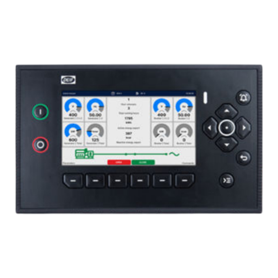
2. Getting started About the display 2.1.1 Display layout The base-mounted controller can run with or without a display, but we recommend that you use a display. The display is the operator's interface to the controller. Item Notes Display screen 7"... -
Page 11: Controls
2.1.2 Controls You can operate the controller with flexible controls. 6-way navigation Button navigation for control, selection, and entering information. Touch screen Easy to use touch interface for most functions. This feature can also be disabled. Configurable buttons Six configurable buttons, allow direct functions from pages. Dedicated buttons Dedicated buttons for start and stop of the asset, Notification centre and Control centre. -
Page 12: Screen Layout
2.1.3 Screen layout Ready for operation 364 h 80 % 10:18:38 Start attempts Total running hours 50.00 50.00 1795 Generator | L1-L2 Busbar | L1-L2 Generator | L1 Busbar | L1 Active energy export kvar kvar kvar Breaker trips Generator | Total Generator | Total Busbar | Total Busbar | Total... -
Page 13: Mimics
2.1.4 Mimics The controller features the latest generation of adaptive mimic for the controller type. SINGLE genset controller OPEN CLOSE OPEN CLOSE GENSET controller CLOSE OPEN EMERGENCY genset controller OPEN CLOSE OPEN CLOSE MAINS controller OPEN CLOSE OPEN CLOSE HYBRID controller CLOSE OPEN Start inverter... -
Page 14: Default Theme Colours
SHORE connection controller CLOSE OPEN BUS TIE breaker controller OPEN CLOSE 2.1.5 Default theme colours Line Colour Notes Black Dead busbar (voltage < 10 % of nominal voltage). Green Live busbar. Amber Unknown state. Voltage present but is not within acceptable range. Operator's manual 4189341416A EN Page 14 of 52... -
Page 15: Navigation Menu
2.1.6 Navigation menu To access the navigation menu, push the Back Island manual 364 h 80 % 10:18:38 Start attempts Dashboard Alarms Total running hours 50.00 50.00 Event logs 1795 Generator | L1-L2 Mains | L1-L2 Generator | L1 Mains | L1 Parameters IO configuration Active energy export... -
Page 16: Status Led
2.1.7 Status LED 10:18:38 50.00 The status LED shows operation and alarm status. The controller has no power or during boot before application Green Power on, normal operation. start. All high severity active alarm(s) Unacknowledged high severity Red flash acknowledged. active alarm(s). -
Page 17: Virtual Keyboards
2.1.8 Virtual keyboards The display has different virtual keyboards to enter information or settings. Some keyboards have unique features for the information that you are entering. The keyboards are designed for use by either button navigation or touch screen. Use either the touch screen or the navigation buttons to highlight, edit, and select information. -
Page 18: Filter
2.1.9 Filter On selected pages you can use a Filter on the list shown by a type of condition. For example, filter the list where it contains a specific word. Sort Filter Show rows where Type Value... Cancel Apply Item Notes Sort Change to Sort. -
Page 19: Sort
2.1.10 Sort On some pages you can use a Filter on the list shown by a sort type. For example, sort the list in descending order of time. Sort Filter Sort by Time Descending Cancel Apply Item Notes Filter Change to Filter. Sort by Select a category to sort the list. -
Page 20: About The Controller Operation
PICUS is the utility software used to configure and monitor the system. You can connect a computer running PICUS to the controller (direct connection) to configure, supervise, send commands and more. Dashboards and display headers are configured from PICUS with the Display designer. More information https://www.deif.com/products/picus/ for the latest software download and information. https://www.deif.com/rtd/picus for the latest PICUS manual. -
Page 21: Control And Operation
3. Control and operation About the equipment control and operation The iE controllers contain all the functions needed to protect and control different types of equipment and their breaker(s). Controllers Notes The SINGLE genset controllers protect and control a genset, and the genset breaker. SINGLE genset controllers SINGLE genset controllers can optionally include a mains connection with or without a mains breaker. - Page 22 Controllers Notes system for the power source is installed and approved, according to the applicable Maritime classification societies. The BUS TIE breaker controller protects and controls a bus tie breaker. The power BUS TIE breaker management system manages the busbar sections. Can be used with other controllers in a controllers Power management system.
-
Page 23: Controller Modes
Controller modes 3.2.1 About the controller mode The iE controllers operate in a controller mode. This mode decides which actions may be taken or how the controller reacts to operational situations. Controller modes: • AUTO - Automatic mode ◦ The controller can automatically start, stop, connect, and disconnect the asset. The operator cannot start a sequence manually, unless the local control setting is enabled for the controller or section. -
Page 24: Change Mode
3.2.2 Change mode You change modes with the Control centre: 1. Push the Control centre button. • The Control centre pop-up is shown on the screen. AUTO MANUAL Switch to dark mode Touch enabled Brightness level • 2. Select the mode required. Operator's manual 4189341416A EN Page 24 of 52... -
Page 25: Asset Control
Asset control 3.3.1 Start the asset Mode Procedure The asset start is typically controlled automatically and the display control is not available. AUTO (Automatic) In a Power management system, if it calculates that more power is required, the controller automatically starts the asset, with the priority order. -
Page 26: Stop The Asset
3.3.2 Stop the asset Mode Procedure The asset stop is controlled automatically and the display control is not available. AUTO (Automatic) In a Power management system, if it calculates that power is not required, the controller automatically stops the asset, with the priority order. To stop the asset: 1. -
Page 27: Breaker Control
Breaker control 3.4.1 Close the breaker Mode Procedure The breaker close is controlled automatically and the display control is not available. AUTO (Automatic) In a Power management system, if it calculates that more power is required, the controller automatically starts the asset and closes the breaker, with the priority order. The asset must be running to close the breaker. -
Page 28: Open The Breaker
3.4.2 Open the breaker Mode Procedure The breaker open is controlled automatically and the display control is not available. AUTO (Automatic) In a Power management system, if it calculates that power is not required, the controller automatically opens the breaker as part of the asset stop sequence. To open the breaker: MANUAL OPEN... -
Page 29: Alarms
Alarms 3.5.1 About the alarms The controller alarms prevent unwanted, damaging, or dangerous situations from occurring. The Operator must review all activated alarms for cause and suitable action. Each alarm has an Alarm condition which determines if the alarm is activated. When the Alarm condition is detected (typically, the operating value reaches the Set point), the controller starts the Time delay (t delay During the Time delay the controller checks whether the Alarm condition remains active:... -
Page 30: Alarm Flowchart
3.5.2 Alarm flowchart 1. The controller detects an Alarm condition. Start 2. The controller checks if the alarm is enabled: • If the alarm is not enabled the controller ignores the alarm. 3. The controller checks if the alarm has an active inhibit. •... -
Page 31: Alarm States
3.5.3 Alarm states Alarm Alarm Symbol Acknowledge Notes condition * action ** • An alarm condition occurred. • An alarm action is active. Active Active Unacknowledged • An alarm requires acknowledgement. • An alarm requires action to clear the alarm condition. •... -
Page 32: Alarms Page
2023-06-19 07:42:00 UTC Warning iE 250 Land SINGLE_GENSET 2023-06-19 07:40:08 UTC Warning iE 250 Land SINGLE_GENSET DEIF 2023-06-19 07:40:01 UTC Trip generator breaker and shutdown engine iE 250 Land SINGLE_GENSET 2023-06-19 07:40:01 UTC Block mains breaker iE 250 Land SINGLE_GENSET... -
Page 33: Alarm Handling And Actions
3.5.5 Alarm handling and actions When alarms are activated in the system, they appear on the Alarms page and the Notification centre. The Notification centre provides quick access for some alarm handling. For more comprehensive alarm actions use the Alarms page. -
Page 34: Logs
Logs 3.6.1 About event logs The event log is a historical recorded list of all system and operator events. For example, the acknowledgement of an alarm, or connection of an asset. If an ECU has been configured with Fieldbus, you can additionally view the DM2 event log. The DM2 event logs are retrieved from the engine and the ECU must be powered up to get the information. -
Page 35: Event Logs Page
Command event 2023-06-22 11:08:57 No NTP server(s) connected Action 2023-06-22 10:40:08 GB closed 2023-06-22 07:40:01 Busbar voltage and frequency OK 2023-06-21 06:27:02 DEIF network redundancy broken Action 2023-06-19 09:39:40 Application initialised correctly Switch log Info Item Notes Event list The symbol shows recorded event. -
Page 36: Dm2 Logs Page
3.6.3 DM2 logs page This shows the engine ECU J1939 historical diagnostic messages (DM2). Search... SPN DESCRIPTION FMI DESCRIPTION SPN NUMBER FMI NUMBER OCCURRENCES Engine speed Data valid But Above Normal... Engine oil pressure Current Below Normal Or Operational... Engine oil temperature Current Below Normal Or Operational... -
Page 37: Notification Centre
Alarms can be either Active or Historical. Active alarms are unacknowledged and Historical alarms are acknowledged. Alarms have an Alarm severity which is configured in the Advanced section of the Parameters configuration. The Alarm severity is shown colour-coded: DEIF network redundancy b... High Warning PCM clock battery failure Medium... -
Page 38: Operator Messages
Operator messages 3.8.1 Controller status texts The controller status texts are shown at the top of the display. The status text shown depends on the type of controller and software package. Not all texts apply for all controller types. LAND MARINE Status text * Description... - Page 39 LAND MARINE Status text * Description Power Core Premium Core management The genset is running and is being regulated Fixed frequency ● ● ● using fixed frequency regulation. The genset is running and is being regulated Frequency droop ● ● ●...
- Page 40 LAND MARINE Status text * Description Power Core Premium Core management MAINS supply is available, and mains breaker MAINS ready ● ● is open. The genset is running and is under manual Manual regulation ● ● ● regulation. A power supply from the shore connection is SC in operation available, and the shore connection breaker is ●...
-
Page 41: Operator Information Messages
LAND MARINE Status text * Description Power Core Premium Core management The controller is busy synchronising the Synchronising SGB / busbar frequency and voltage to close the ● ● breaker. The controller is synchronising the genset to Synchronising GB the busbar frequency and voltage to close the ●... - Page 42 LAND MARINE Operator info Additional information Power Core Premium Core management The breaker is already open and cannot be Breaker already opened ● ● ● ● opened again. In Switchboard control, operator actions BTB block not possible in cannot be performed from the controller ●...
- Page 43 LAND MARINE Operator info Additional information Power Core Premium Core management In Switchboard control, operator actions Engine block not possible cannot be performed from the controller ● ● in SWBD interfaces. The command has already been received. Engine is stopping The controller is executing the engine stop ●...
- Page 44 LAND MARINE Operator info Additional information Power Core Premium Core management In Switchboard control, operator actions GB open and stop not cannot be performed from the controller ● ● possible in SWBD interfaces. The GB open was cancelled by a GB close GB open cancelled ●...
- Page 45 LAND MARINE Operator info Additional information Power Core Premium Core management It is not possible to change to MANUAL or Mode change locked AUTO mode while the controller is in ● ● Switchboard control. There is no genset in AUTO and Ready for No genset ready to start operation to take over the load after the ●...
- Page 46 LAND MARINE Operator info Additional information Power Core Premium Core management The Block shore connection breaker close SCB close unblocked ● ● function is not active. The SCB open was cancelled by an SCB SCB open cancelled ● ● close command. In Switchboard control, operator actions SCB open not possible in cannot be performed from the controller...
- Page 47 LAND MARINE Operator info Additional information Power Core Premium Core management The shaft generator Fixed speed parameter is configured, but not enabled. The shaft SG fixed speed generator breaker does not close until it is ● deactivated enabled. Or the Fixed speed parameter is not enabled.
- Page 48 LAND MARINE Operator info Additional information Power Core Premium Core management Zero pitch deactivated The Zero pitch function is not active. ● In Switchboard control, operator actions Zero pitch not possible in cannot be performed from the controller ● SWBD interfaces.
-
Page 49: Configuration
4. Configuration Parameters page Search... Nominal settings Engine Running detection Generator Feedback type Busbar Engine ready Power transformer Regulators Delay Breakers Frequency running detection Local power management RPM running detection Power management rules System power management MPU setup Communication Oil pressure running detection Local Expand Expand... -
Page 50: Input/Output Configuration
Input/output configuration 4.2.1 About input or output channels The controller channels are configurable but depend on the controller type, parameters, functions and alarms available. Some hardware types support bi-directional channels, where you can configure if the channel is input or output. More information For the hardware specifications and terminal allocations, see the Technical specifications in the Data sheet: •... -
Page 51: I/O Configuration Page
4.2.2 I/O configuration page Search... MIO2.1 MIO2.1 52, 55 DO 40, 41 AO AVR output Output type Alarm Function 43, 44 AO GOV output Select function Clear Any latched alarm 46, 48 DO Status OK 46, 49 DO Any alarm 46, 50 DO Crank 46, 51 DO Run coil 52, 53 DO Breaker close... -
Page 52: End-Of-Life
WEEE. In Europe, local governments are responsible for facilities to receive WEEE. If you need more information on how to dispose of DEIF WEEE, please contact DEIF. Operator's manual 4189341416A EN...
Need help?
Do you have a question about the iE Display and is the answer not in the manual?
Questions and answers