Table of Contents
Advertisement
Quick Links
Advertisement
Table of Contents

Subscribe to Our Youtube Channel
Related Manuals for FDS FD70ARM-G


Summary of Contents for FDS FD70ARM-G
- Page 1 Revision Date: Rev: Document Number: 05/22/2017 MAN – FD70ARM-G Page 1 of 16 Installation and Operation Manual FD70ARM-G 7 Inch Dual LCD System © 2017 FDS Avionics Corp. TECHNICAL SUPPORT All Rights Reserved. 470-239-7421 or FDSAvionics.com...
-
Page 2: Table Of Contents
Operation Instructions ..................12 Monitor Control Buttons................... 12 Technical Drawing .................... 13 Technical Support ..................... 14 Instructions for Continued Airworthiness ............14 Warranty ......................15 Log of Revisions ....................16 © 2017 FDS Avionics Corp. TECHNICAL SUPPORT All Rights Reserved. 470-239-7421 or FDSAvionics.com... -
Page 3: General Information
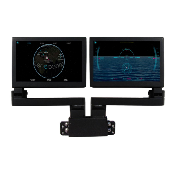
Page 3 of 16 General Information The FD70ARM-G is a 7" Dual LCD System, utilizing the latest version of our popular 7” Widescreen Display. Each arm unit is made of two separate parts, the metal enclosed LCD screen and the articulating arm. -
Page 4: Specifications
Aluminum Installation Instructions All cabin entertainment equipment, such as the FD70ARM-G, should be installed on a non-essential bus and have a dedicated circuit breaker. It is a requirement that a switch be installed in the cockpit so that the pilot can de-energize the entertainment system should it become necessary. -
Page 5: Technical Drawing - Base
Revision Date: Rev: Document Number: 05/22/2017 MAN – FD70ARM-G Page 5 of 16 Technical Drawing - Base © 2017 FDS Avionics Corp. TECHNICAL SUPPORT All Rights Reserved. 470-239-7421 or FDSAvionics.com... -
Page 6: Wiring Suggestions
75 Ohm video isolation transformer such as Deerfield Laboratory, Inc. Part No. 162-1 (www.deerfieldlab.com, (650) 632-4090). In most cases this should be added to the video output of the source. © 2017 FDS Avionics Corp. TECHNICAL SUPPORT All Rights Reserved. -
Page 7: Vga Wiring
5 separate coaxial cables, color-coded to match the functions of the wires. We recommend coax cables be terminated using solder sleeve coaxial cable terminators such as Raychem Part Number CWT-4174-W122-5/9. © 2017 FDS Avionics Corp. TECHNICAL SUPPORT All Rights Reserved. 470-239-7421 or FDSAvionics.com... -
Page 8: Power & Ground Wiring
Also, use short heavy gauge wire and a clean tight connection for ground. It is the installer’s responsibility to understand the product’s requirements to install the product in compliance with industry standards and safety. © 2017 FDS Avionics Corp. TECHNICAL SUPPORT All Rights Reserved. -
Page 9: Power/Video Pinouts
Red Ground (Pin 6 on Standard VGA) Green Ground (Pin 7 on Standard VGA) Horizontal Sync (Pin 13 on Standard VGA) Vertical Sync (Pin 14 on Standard VGA) © 2017 FDS Avionics Corp. TECHNICAL SUPPORT All Rights Reserved. 470-239-7421 or FDSAvionics.com... - Page 10 Video Green (-) (T568B Cat5 Pin 5) Video Green (+) (T568B Cat5 Pin 4) Video Ground (T568B Cat5 Pin 8) Note: Cat5 Pin 7 is not used © 2017 FDS Avionics Corp. TECHNICAL SUPPORT All Rights Reserved. 470-239-7421 or FDSAvionics.com...
- Page 11 Coax Contact P/N: Conec – 132J30029X (for use with RG179)* *Other cable type contacts available from Conec MATING FACE Description Number 28VDC Power 28VDC Ground HDSDI IN © 2017 FDS Avionics Corp. TECHNICAL SUPPORT All Rights Reserved. 470-239-7421 or FDSAvionics.com...
-
Page 12: Operation Instructions
Page 12 of 16 Operation Instructions The FD70ARM-G is continuously on but can be de-energized by removing power from the entertainment system. No pilot or aircrew action is necessary during flight or ground operation. Passengers can change the video output from the FD70ARM-G using the video source select switch on the LCD monitor, or remotely throughout the cabin with the included IR remotes. -
Page 13: Technical Drawing
Revision Date: Rev: Document Number: 05/22/2017 MAN – FD70ARM-G Page 13 of 16 Technical Drawing © 2017 FDS Avionics Corp. TECHNICAL SUPPORT All Rights Reserved. 470-239-7421 or FDSAvionics.com... -
Page 14: Technical Support
05/22/2017 MAN – FD70ARM-G Page 14 of 16 Technical Support Should you have any questions concerning this product or other FDS Avionics Corp. products, please contact our Product Support representatives at (470) 239-7421. FDS Avionics Corp. 6435 Shiloh Road Alpharetta, GA 30005... -
Page 15: Warranty
Warranty Information All FDS Avionics Corp. (FDS) products are warranted to be free from material or manufacturing defects for a period of 24 months from the date of shipment for General Aviation customers or 12 months from the date of shipment for Government/Special Mission customers. -
Page 16: Log Of Revisions
02/26/2009 2,10 Updated specifications, warranty info Update picture, specs, pinout, monitor buttons, 01/08/2010 1,2,5,6,7,11 assembly drawing Added pinout for FD70ARM-G Ver SDI, updated 04/11/2011 VGA wiring New Corporate Name, New Branding, New 5/22/2017 Warranty, Drawings,etc. © 2017 FDS Avionics Corp.
Need help?
Do you have a question about the FD70ARM-G and is the answer not in the manual?
Questions and answers